ILC RF System R&D. Chris Adolphsen, SLAC. Section of 1.3 GHz SC Linac. June 29, 2007 PAC07 Talk FRYC01
|
|
|
- Shawn Henry
- 5 years ago
- Views:
Transcription


1 ILC RF System R&D Chris Adolphsen, SLAC June 29, 2007 PAC07 Talk FRYC01 Section of 1.3 GHz SC Linac
2 ILC Main Linac RF Unit (1 of 560) RF System Gradient = 31.5 MV/m Rep Rate = 5 Hz Beam Current = 9.0 ma Cavity Power = 280 kw Cavity Fill Time = 600 μs Bunch Train Length = 970 μs (9-8-9 Cavities per Cryomodule)
3 Many ILC/XFEL Presentations Modulators TUXC03 WEPMS044 THIBKI04 TUOAC02 THOBKI02 WEPMN113 WEPMN073 WEPMS028 Klystrons WEPMN013 THIBKI03 WEPMS093 THIBKI01 Design and Status of the XFEL RF System High Power Switch for the SMTF Modulator Developments of Long-pulse Klystron Modulator for the STF Development and Testing of the ILC Marx Modulator Marx Bank Technology for the ILC A High Voltage Hard Switch for the ILC A New Klystron Modulator for XFEL based on PSM Technology Converter-Modulator Design and Operations Testing of 10 MW MBKs for the European X-ray FEL at DESY Klystron Development by TETD Grid-less IOT for Accelerator Applications RF Sources for the ILC
4 ILC/XFEL Presentations (Cont.) Klystrons (cont) WEPMN054 THPAS063 WEPMN119 RF Distribution WEPMS043 MOPAN015 Power Couplers WEPMN032 WEPMN027 WEPMS017 WEPMS041 WEPMS049 Electron Gun and Cavity Designs for High Power Gridded Tube Second Order Ruled Surfaces in Design of Sheet Beam Guns High-Power Ribbon-Beam Klystron An RF Waveguide Distribution System for the ILC Test Accelerator at Fermilab s NML Compact Waveguide Distribution with Asymmetric Shunt Tees for the European XFEL R&D Status of KEK High Gradient Cavity Package Construction of the Baseline SC Cavity System for STF at KEK High-Power Coupler Component Test Stand Status and Results Multipacting Simulations of TTF-III Coupler Components A Coaxial Coupling Scheme for the ILC SRF Cavity
")
5 Pulse Transformer Modulator (ILC Baseline) IGCT s
6 TESLA/XFEL Modulator Development at DESY 11 units have been built during past 10 years, 3 by FNAL and 8 by industry (PPT with components from ABB, FUG, Poynting) thru DESY funding. Expanding vendor base for XFEL Ordered prototypes from two vendors Imtech-Vonk (Baseline Pulse Transformer) Thompson (Pulse Step Modulator) Test in new facility in Zuethen that includes the modulator, cable, pulse transformer, klystron, interlocks and controls Expect delivery of ~ 30 modulators in For ILC, compliments Marx and other alternative designs


7 Pulse Step Modulator Features 24, ~ 0.5 kv, Marx-like cells are summed to drive a 12:1 transformer Bouncer circuit eliminated FPGA based control 2 stages for redundancy Pulse width modulation for fine control Slew rate and pulse shape controllable Concept used in PS s Thompson built for the W7-X experimental fusion reactor
8 New Pulse Transformer Modulator at FNAL with SLAC-Supplied Switch Capacitor Banks IGBT Redundant Switch Bouncer Choke


9 New Pulse Transformer Modulator at KEK Nichicon (Kusatsu) Corporation and KEK Collaboration Features crowbar-less system with optimized IGBT snubber circuit, compact and highly reliable self-healing capacitors, HV & LV twin pulse transformers of laminated steel core for reduced tank volume IGBT Stack Modulator
 and to improve its")

10 SLAC Marx Modulator Develop alternative Marx approach to reduce the cost, size and weight of the modulator (no oil-filled transformers) and to improve its efficiency, reliability and manufacturability. 2 m Fine Vernier 120 kv Output Cable Buck Regulator Coarse Vernier (3+1 Redundancy) 12 kv Cells (10+2 Redundancy)


11 12 kv Cell Detail 4+1 Redundant Switch Arrays for charge, discharge 6+2 Redundant Capacitors
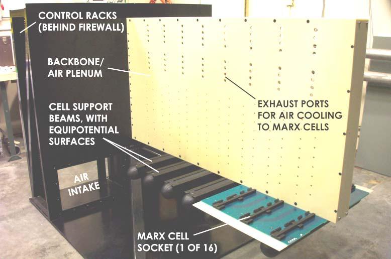
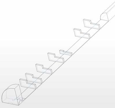
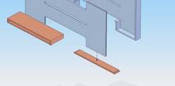
12 Cantilever Backbone

13 MARX Prototype


14 MARX Waveforms With 10 cards but w/o Vernier, which will be ready this Summer 120kV, 120 μsec Pulse 100kV, 1.4 ms Leveled Pulse
15 Marx Status & Plans Prototype built that has achieved peak power goals. Currently sorting IGBTs and improving protection circuits (run at low rep rate). Will then do 100 h full average power test and modify design to include new capacitor discharge switches, begin 2000 h test. In parallel, complete Vernier, Buck Regulator Boards. Complete full power 2000 h test with resistive load. Install unit in air-water cooled enclosure and move to SLAC ESB to operate Toshiba 10 MW Multi-Beam Klystron


")

16 Stangenes Marx Generator (for NATO Radar Systems) Produces 90 kv, 50A, 100 μsec Pulses

17 DTI Marx Under Construction (Phase II SBIR) ILC Modulator kv, A, 1.5 ms, 5 Hz Klystron Pulses ~ 750 Modulators Required Use Marx topology to beat the long pulse problem Switch additional stages as pulse droops, maintain flattop with affordable size capacitor bank Minimize Overall Size and Cost SBIR Goal Design, build, deliver a fully functioning first article for evaluation & tube testing Advantage of Marx for ILC COMPACT!!!... LOW COST!!! M. Kempkes


18 Other Alternative Modulators SNS High Voltage Converter Modulator at SLAC ENERGY STORAGE SWITCHING BOOST TRANS- FORMER HV RECTIFIER AND FILTER NETWORK -HV -HV -HV 10ohm 20mH.03uF 6 EACH RTN AØ BØ CØ.03uF.05uF VMON 6 EACH HV OUTPUT

19 DTI Series Switch Modulator (Phase II SBIR) DTI is building a 120 kv, 130 A IGBT Series Switch with a bouncer to be delivered to SLAC by the end of 2007
")

 CPI (1)")
20 L-Band Klystrons Baseline: 10 MW Multi-Beam Klystrons (MBKs) with ~ 65% Efficiency: Being Developed by Three Tube Companies in Collaboration with DESY Thales (6 built) CPI (1) Toshiba (1)


21 Test of First Toshiba MBK at DESY Operated 750 hours, 80 % at full power Efficiency = 65 %, which meets design goal Nominal Power for 31.5 MV/m Operation at ILC 6-Beam Gun


22 Horizontal MBKs for XFEL Expect the first of three horizontal MBKs this Fall. DESY is currently working with three companies to design the klystron interface to the transformer tank

 while still maintaining low")


23 Sheet Beam Klystron Development at SLAC Why Sheet Beam? Allows higher beam current (at a given beam voltage) while still maintaining low current density for efficiency Will be smaller and lighter than other options PPM focusing eliminates power required for solenoid Designed to be MBK plug compatible with similar or better efficiency

24 Beam Transport and RF The elliptical beam is focused in a periodic permanent magnet stack that is interspersed with rf cavities Lead shielding Magnetically shielded from outside world Have done: Electron beam RF cavity Permanent Magnet Cell 3D Gun simulations of a 130 A, 40:1 aspect ratio elliptical beam traversing 30 period structures. 3D PIC Code simulations of rf interaction with the beam.
25 SBK Simulations Gun Current RF Cavities Cathode Temp Magnetic Cells


26 SBK Simulations Gun Current RF Cavities Cathode Temp Magnetic Cells


27 Sheet Beam Program Build beam tester and klystron by Summer The beam tester will validate 3-D beam transport simulations and allow a more rapid turnaround for electron gun changes. The klystron will be developed in parallel with little feedback from the beam tester. A rebuild of the klystron can incorporate design changes motivated by the beam tester. Gun and Beam Profile Monitor Carbon beam probe assembly
28 Baseline RF Distribution System Fixed Tap-offs Circulators Alternative RF Distribution System Variable Tap-offs (VTOs) 3 db Hybrids

29 The KEK Superconducting Test Facility (STF) Will Use Both Individual and Tree-Like Feeds STF Phase 1: Two Cryomodules of Four Cavities Each
")
30 XFEL RF Distribution System Switched from a Individual Feed System To a Tree-Like (2D) System


31 Replaced 3-Stub Tuner with Phase Shifter


32 Feed Cavities In Pairs
33 At SLAC, Developing Variable Tap-Offs Using Mode Rotation
34 RF Distribution System without Circulators but with Variable Tap-offs (VTOs) RF Input Variable Tap-off Load Hybrid RF Feeds Machined Aluminum, Dip-Brazed Rotatable Flanges Length = 1.6 m 3 db Hybrid


35 SLAC is building VTOs and custom hybrids and acquiring parts to assemble rf distribution systems for FNAL cryomodules
36 Variable Tap-Off (VTO) Low Power Test 0 VTO with ~0 Degrees Rotation 0 VTO with ~45 Degrees Rotation S Parameter Amplitude (db) S11 S21 S31 S Parameter Amplitude (db) S11 S21 S Frequency (GHz) Frequency (GHz) 3 2 S 11 = db S 21 = db S 31 = db 4 1 S 11 = db S 21 = db S 31 = db
37 Gradient Optimization with VTOs and Circulators Consider uniform distribution of gradient limits (G lim ) i from 22 to 34 MV/m in a 26 cavity rf unit - adjust cavity Q s and/not cavity power (P) to maximize overall gradient while keeping gradient uniform (< 1e-3 rms) during bunch train Optimized 1 G / G lim ; results for 100 seeds Case Not Sorted [%] Sorted [%] Individual P s and Q s (VTO and Circ) 1 P, individual Q s 2.7 ± ± 0.4 (Circ but no VTO) P s in pairs, Q s in pairs 7.2 ± ± 0.2 (VTO but no Circ) 1 P, Q s in pairs 8.8 ± ± 0.5 (no VTO, no Circ) G i set to lowest G lim 19.8 ± ± 2.0 (no VTO, no Circ)
38 Baseline TTF-3 Coupler Design Design complicated by need for tunablity (Qext), HV hold-off, dual vacuum windows and bellows for thermal expansion. Input Power

39 Baseline and Alternative Designs Cold Window Bias-able Variable Qext Cold Coax Dia. # Fabricated TTF-3 Cylindrical yes yes 40 mm 62 KEK2 Capacitive Disk no no 40 mm 3 KEK1 Tristan Disk no no 60 mm 4 LAL TW60 LAL TTF5 Disk Cylindrical possible possible possible possible 62 mm 62 mm 2 2


40 Coupler Assembly and Processing Orsay Facilities (shown below) - can process about 30 couplers / yr. Down to ~ 20 hours of rf processing time. SLAC building similar assembly facilities to provide FNAL with conditioned TTF-3 couplers.
41 SLAC Clean Room Layout Storage Lockers SLAC Modifications Eliminate separate material pass-through More class 10 area Class 1000 => 100 Remote vacuum bake Office Space Ramp if raised floor Gowning Area Class 100 Class 10 Air Shower Air Handling System Vacuum Oven possible upgrade


42 SLAC Coupler Connection Cavity Opens fully for cleaning compared to enclosed Orsay design, and does not use indium seals as in KEK split-wg design Pump-Out Port 25 mm 38 mm Perturbed TM 110 Mode Pillbox Cavity

43 Coupler Component Test Stand (SLAC / LLNL) Facility assembled and operating initially testing 600 mm long, 40 mm diameter stainless-steel coaxial section RF In RF Out WG to window RF load coax window RF in DUT

")

44 A Reliable Center Conductor Mating Scheme was Developed Outer conductor wall of the Device Under Test (DUT) Slip-fit side to accommodate expansion Threaded anchor side

45 Coupler Component Test Stand Device Under Test PMT e-pickup PMT
46 Current of Ion pump 10C Second Processing of a 600 mm Long S/S 10B Section ua MW@1.1ms 13hr 1000 Power of klystron: kw Pulse W idth: us E-pickup: V Delayed time of the signal from e-pickup compared with RF pulse us mv -1 Upstream PMT Downstream PMT

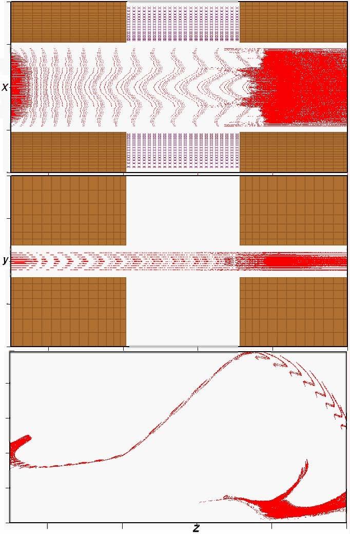
47 Evidence of Multipacting after Initial Processing
.")

48 Electron Probe Signal Signal has delayed turn-on wrt to rf pulse that varies over time (delay time shortens in presence of magnetic field or high power spike). Shape changes with power, amplitude correlated with pressure level. After processing, signal becomes small and unstable, sometimes disappearing for long periods. Waveforms (50 μs / division) Harmonic (1.3 GHz) Content Relative Amp -vs- Time (μs) RF Input Low Freq Probe Signal


49 Current SLAC L-Band Test Stand Capture Cavity Produces 5 MW, 1.4 msec pulses at 5 Hz with a TH2104C klystron and a SNS-type modulator Source powers a coupler test stand and a normal-conducting ILC e+ capture cavity RF Switch Coupler Component Test Stand & Coupler Processing


50 ILC Positron Capture Cavity Prototype Goal: Power with 5 MW, 1 msec pulses to produce 15 MV/m gradient


51 Brazed Coupler and Body Subassemblies Ready for Final Brazing

52 Two New L-Band Test Stands Each new test stand will have Modulator with Charging Power Supply Oil Tank with HV Water Load Filament PS Transformer Klystron Socket Instrumentation and Controls Will run independently, 24/7, with summary data archived for trends, detailed data for faults. HV Water Load Non-Conducting Tubes Water + Borax Flow Oil HV Connection
53 FY08-09 SLAC Deliverables Design-for-Manufacturability Marx (start in FY07) 6 Modulator Production Units Toshiba10 MW MBKs (purchased in FY07) Sheet Beam Klystron (started in FY07) 6 Klystron Production Units 5 RF Distribution Systems to FNAL (1 in FY07) 60 Processed Couplers to FNAL (12 starting in FY07) Coupler Development and Prototypes 5 Production RF Sources Operating at SLAC (1 at FNAL)
54 RF System Summary SLAC pursuing alternate designs while XFEL concentrating more on baseline approaches. Marx Modulator approach looks promising. First Toshiba 10 MW MBK successful, Thales tubes have run tens of khour, design evolved to correct problems. Horizontal versions being developed. A sheet beam klystron is being built that is more compact, lighter and likely less expensive than the MBK. Evaluating various rf distribution approaches to lower system cost and maximize useable gradient. US program ramping up, includes coupler development.
L-Band RF R&D. SLAC DOE Review June 15 th, Chris Adolphsen SLAC
 L-Band RF R&D SLAC DOE Review June 15 th, 2005 Chris Adolphsen SLAC International Linear Collider (ILC) RF Unit (TESLA TDR Layout) Gradient = 23.4 MV/m Bunch Spacing = 337 ns Fill Time = 420 µs Train Length
INFN School on Electron Accelerators. RF Power Sources and Distribution
 INFN School on Electron Accelerators 12-14 September 2007, INFN Sezione di Pisa Lecture 7b RF Power Sources and Distribution Carlo Pagani University of Milano INFN Milano-LASA & GDE The ILC Double Tunnel
XFEL High Power RF System Recent Developments
 XFEL High Power RF System Recent Developments for the XFEL RF Group Outline XFEL RF System Requirements Overview Basic Layout RF System Main Components Multibeam Klystrons Modulator RF Waveguide Distribution
WG2 Group Summary. Chris Adolphsen Terry Garvey Hitoshi Hayano
 WG2 Group Summary Chris Adolphsen Terry Garvey Hitoshi Hayano Linac Options Fest On Thursday afternoon, various experts summarized the linac baseline options. Although hard choices have yet to be made,
Solid State Modulators for X-Band Accelerators
 Solid State Modulators for X-Band Accelerators John Kinross-Wright Diversified Technologies, Inc. Bedford, Massachusetts DTI X-Band Experience Developed and built two completely different NLC-class modulator
DEVELOPMENT OF A 10 MW SHEET BEAM KLYSTRON FOR THE ILC*
 DEVELOPMENT OF A 10 MW SHEET BEAM KLYSTRON FOR THE ILC* D. Sprehn, E. Jongewaard, A. Haase, A. Jensen, D. Martin, SLAC National Accelerator Laboratory, Menlo Park, CA 94020, U.S.A. A. Burke, SAIC, San
RF plans for ESS. Morten Jensen. ESLS-RF 2013 Berlin
 RF plans for ESS Morten Jensen ESLS-RF 2013 Berlin Overview The European Spallation Source (ESS) will house the most powerful proton linac ever built. The average beam power will be 5 MW which is five
Detailed Design Report
 Detailed Design Report Chapter 4 MAX IV Injector 4.6. Acceleration MAX IV Facility CHAPTER 4.6. ACCELERATION 1(10) 4.6. Acceleration 4.6. Acceleration...2 4.6.1. RF Units... 2 4.6.2. Accelerator Units...
Next Linear Collider. The 8-Pack Project. 8-Pack Project. Four 50 MW XL4 X-band klystrons installed on the 8-Pack
 The Four 50 MW XL4 X-band klystrons installed on the 8-Pack The Demonstrate an NLC power source Two Phases: 8-Pack Phase-1 (current): Multi-moded SLED II power compression Produce NLC baseline power: 475
IOT OPERATIONAL EXPERIENCE ON ALICE AND EMMA AT DARESBURY LABORATORY
 IOT OPERATIONAL EXPERIENCE ON ALICE AND EMMA AT DARESBURY LABORATORY A. Wheelhouse ASTeC, STFC Daresbury Laboratory ESLS XVIII Workshop, ELLETRA 25 th 26 th November 2010 Contents Brief Description ALICE
Experience with the Cornell ERL Injector SRF Cryomodule during High Beam Current Operation
 Experience with the Cornell ERL Injector SRF Cryomodule during High Beam Current Operation Matthias Liepe Assistant Professor of Physics Cornell University Experience with the Cornell ERL Injector SRF
RF considerations for SwissFEL
 RF considerations for H. Fitze in behalf of the PSI RF group Workshop on Compact X-Ray Free Electron Lasers 19.-21. July 2010, Shanghai Agenda Introduction RF-Gun Development C-band development Summary
RF Upgrades & Experience At JLab. Rick Nelson
 RF Upgrades & Experience At JLab Rick Nelson Outline Background: CEBAF / Jefferson Lab History, upgrade requirements & decisions Progress & problems along the way Present status Future directions & concerns
3 cerl. 3-1 cerl Overview. 3-2 High-brightness DC Photocathode Gun and Gun Test Beamline
 3 cerl 3-1 cerl Overview As described before, the aim of the cerl in the R&D program includes the development of critical components for the ERL, as well as the construction of a test accelerator. The
Pulsed Klystrons for Next Generation Neutron Sources Edward L. Eisen - CPI, Inc. Palo Alto, CA, USA
 Pulsed Klystrons for Next Generation Neutron Sources Edward L. Eisen - CPI, Inc. Palo Alto, CA, USA Abstract The U.S. Department of Energy (DOE) Office of Science has funded the construction of a new accelerator-based
!"!3
 Abstract A single-mode 500 MHz superconducting cavity cryomodule has been developed at Cornell for the electronpositron collider/synchrotron light source CESR. The Cornell B-cell cavity belongs to the
A HIGH POWER LONG PULSE HIGH EFFICIENCY MULTI BEAM KLYSTRON
 A HIGH POWER LONG PULSE HIGH EFFICIENCY MULTI BEAM KLYSTRON A.Beunas and G. Faillon Thales Electron Devices, Vélizy, France S. Choroba DESY, Hamburg, Germany Abstract THALES ELECTRON DEVICES has developed
The TESLA RF System. S. Choroba. for the TESLA Collaboration. DESY Notkestr. 85, D Hamburg, Germany
 The TESLA RF System S. Choroba for the TESLA Collaboration DESY Notkestr. 85, D-22603 Hamburg, Germany Abstract. The TESLA project proposed by the TESLA collaboration in 2001 is a 500 to 800GeV e+/e- linear
DESIGN AND PERFORMANCE OF L-BAND AND S-BAND MULTI BEAM KLYSTRONS
 DESIGN AND PERFORMANCE OF L-BAND AND S-BAND MULTI BEAM KLYSTRONS Y. H. Chin, KEK, Tsukuba, Japan. Abstract Recently, there has been a rising international interest in multi-beam klystrons (MBK) in the
RF Solutions for Science.
 RF Solutions for Science www.thalesgroup.com State-of-the-art RF sources for your scientific needs High-power klystrons HIGH KLYSTRONS WITH RF LONG PULSE above 50 μs Thales has been one of the leading
2 Work Package and Work Unit descriptions. 2.8 WP8: RF Systems (R. Ruber, Uppsala)
") 2 Work Package and Work Unit descriptions 2.8 WP8: RF Systems (R. Ruber, Uppsala) The RF systems work package (WP) addresses the design and development of the RF power generation, control and distribution
2 Work Package and Work Unit descriptions 2.8 WP8: RF Systems (R. Ruber, Uppsala) The RF systems work package (WP) addresses the design and development of the RF power generation, control and distribution
A New 4MW LHCD System for EAST
 1 EXW/P7-29 A New 4MW LHCD System for EAST Jiafang SHAN 1), Yong YANG 1), Fukun LIU 1), Lianmin ZHAO 1) and LHCD Team 1) 1) Institute of Plasma Physics, Chinese Academy of Sciences, Hefei, China E-mail
Modulator Overview System Design vs. Tunnel Topologies. Snowmass Workshop August 16, 2005 Ray Larsen for the SLAC ILC Group
 Modulator Overview System Design vs. Tunnel Topologies Snowmass Workshop August 16, 2005 Ray Larsen for the SLAC ILC Group Outline! I. Modulator Options vs. Topologies! II. Preliminary Cost Estimates!
Introduction: CW SRF linac types, requirements and challenges High power RF system architecture
 RF systems for CW SRF linacs S. Belomestnykh Cornell University Laboratory for Elementary-Particle Physics LINAC08, Victoria, Canada October 1, 2008 Outline L band Introduction: CW SRF linac types, requirements
Nick Walker DESY MAC
 Nick Walker DESY MAC 4.5.2006 XFEL X-Ray Free-Electron Laser DESY ILC Project Group Accelerator Experimentation Behnke, Elsen, Walker (chair) WP 15, 16 WP 4-7 Accelerator Physics and Design WP 6 High Gradient
Evaluation of Performance, Reliability, and Risk for High Peak Power RF Sources from S-band through X-band for Advanced Accelerator Applications
 Evaluation of Performance, Reliability, and Risk for High Peak Power RF Sources from S-band through X-band for Advanced Accelerator Applications Michael V. Fazio C. Adolphsen, A. Jensen, C. Pearson, D.
Working Group 2 Introductory presentation. Convenors C. Adolphsen, T. Garvey, H. Hayano
 Working Group 2 Introductory presentation. Convenors C. Adolphsen, T. Garvey, H. Hayano Topics covered by WG2 Modulators / klystrons RF wave-guide distribution Low Level RF Beam interfaces (quadrupoles,
Pulses inside the pulse mode of operation at RF Gun
 Pulses inside the pulse mode of operation at RF Gun V. Vogel, V. Ayvazyan, K. Floettmann, D. Lipka, P. Morozov, H. Schlarb, S. Schreiber FLASH Seminar, DESY March 29, 2011 Contents Why we need a PiPmode
Towards an X-Band Power Source at CERN and a European Structure Test Facility
 Towards an X-Band Power Source at CERN and a European Structure Test Facility Erk Jensen and Gerry McMomagle CERN The X-Band Accelerating Structure Design and Test-Program Workshop Day 2: Structure Testing
RF Power Generation II
 RF Power Generation II Klystrons, Magnetrons and Gyrotrons Professor R.G. Carter Engineering Department, Lancaster University, U.K. and The Cockcroft Institute of Accelerator Science and Technology Scope
US-ILC Waveguide Industrialization Study. Marc Ross, Chris Nantista and Chris Adolphsen
 US-ILC Waveguide Industrialization Study Marc Ross, Chris Nantista and Chris Adolphsen ILC Local Power Distribution System (LPDS) variable power divider, pressurizable, 0-100%, phase stable pressure window
J/NLC Progress on R1 and R2 Issues. Chris Adolphsen
 J/NLC Progress on R1 and R2 Issues Chris Adolphsen Charge to the International Linear Collider Technical Review Committee (ILC-TRC) To assess the present technical status of the four LC designs at hand,
TECHNICAL SPECIFICATION Multi-beam S-band Klystron type BT267
 TECHNICAL SPECIFICATION Multi-beam S-band Klystron type BT267 The company was created for the development and manufacture of precision microwave vacuum-electron-tube devices (VETD). The main product areas
 STF Beta
 STATUS OF THE SWISSFEL C-BAND LINEAR ACCELERATOR
 Proceedings of FEL213, New York, NY, USA STATUS OF THE SWISSFEL C-BAND LINEAR ACCELERATOR F. Loehl, J. Alex, H. Blumer, M. Bopp, H. Braun, A. Citterio, U. Ellenberger, H. Fitze, H. Joehri, T. Kleeb, L.
Spear3 RF System Sam Park 11/06/2003. Spear3 RF System. High Power Components Operation and Control. RF Requirement.
 Spear3 RF System RF Requirement Overall System High Power Components Operation and Control SPEAR 3 History 1996 Low emittance lattices explored 1996 SPEAR 3 proposed 11/97 SPEAR 3 design study team formed
A New High Intensity Proton Source. The SCRF Proton Driver. (and more!) at Fermilab. July 15, Bill Foster SRF2005
 at Fermilab. July 15, Bill Foster SRF2005") The SCRF Proton Driver A New High Intensity Proton Source (and more!) at Fermilab Bill Foster SRF2005 July 15, 2005 Outline The Concept Fermilab Strategic Context Proton Driver SRF Linac Design Ferrite
The SCRF Proton Driver A New High Intensity Proton Source (and more!) at Fermilab Bill Foster SRF2005 July 15, 2005 Outline The Concept Fermilab Strategic Context Proton Driver SRF Linac Design Ferrite
ILC-LNF TECHNICAL NOTE
 IL-LNF EHNIAL NOE Divisione Acceleratori Frascati, July 4, 2006 Note: IL-LNF-001 RF SYSEM FOR HE IL DAMPING RINGS R. Boni, INFN-LNF, Frascati, Italy G. avallari, ERN, Geneva, Switzerland Introduction For
NSLS-II RF Systems James Rose, Radio Frequency Group Leader PAC 2011
 NSLS-II RF Systems James Rose, Radio Frequency Group Leader PAC 2011 1 BROOKHAVEN SCIENCE ASSOCIATES Introduction Linac RF cavities and klystrons Booster Cavity-Transmitter Storage Ring 500 MHz SRF cavity
Status of BESSY II and berlinpro. Wolfgang Anders. Helmholtz-Zentrum Berlin for Materials and Energy (HZB) 20th ESLS-RF Meeting
 20th ESLS-RF Meeting") Status of BESSY II and berlinpro Wolfgang Anders Helmholtz-Zentrum Berlin for Materials and Energy (HZB) 20th ESLS-RF Meeting 16.-17.11.2016 at PSI Outline BESSY II Problems with circulators Landau cavity
Status of BESSY II and berlinpro Wolfgang Anders Helmholtz-Zentrum Berlin for Materials and Energy (HZB) 20th ESLS-RF Meeting 16.-17.11.2016 at PSI Outline BESSY II Problems with circulators Landau cavity
High Brightness Injector Development and ERL Planning at Cornell. Charlie Sinclair Cornell University Laboratory for Elementary-Particle Physics
 High Brightness Injector Development and ERL Planning at Cornell Charlie Sinclair Cornell University Laboratory for Elementary-Particle Physics June 22, 2006 JLab CASA Seminar 2 Background During 2000-2001,
X-Band Klystron Development at
 X-Band Klystron Development at SLAC Slide 1 The Beginning X-band klystron work began at SLAC in the mid to late 80 s to develop high frequency (4x SLAC s-band), high power RF sources for the linear collider
Present Status and Future Upgrade of KEKB Injector Linac
 Present Status and Future Upgrade of KEKB Injector Linac Kazuro Furukawa, for e /e + Linac Group Present Status Upgrade in the Near Future R&D towards SuperKEKB 1 Machine Features Present Status and Future
Review of Diamond SR RF Operation and Upgrades
 Review of Diamond SR RF Operation and Upgrades Morten Jensen on behalf of Diamond Storage Ring RF Group Agenda Stats X-ray and LN2 pressure results Cavity Failure Conditioning in the RFTF Cavity Simulations
Current status of XFEL/SPring-8 project and SCSS test accelerator
 Current status of XFEL/SPring-8 project and SCSS test accelerator Takahiro Inagaki for XFEL project in SPring-8 inagaki@spring8.or.jp Outline (1) Introduction (2) Key technology for compactness (3) Key
The ESS Accelerator. For Norwegian Industry and Research. Oslo, 24 Sept Håkan Danared Deputy Head Accelerator Division Group Leader Beam Physics
 The ESS Accelerator For Norwegian Industry and Research Oslo, 24 Sept 2013 Håkan Danared Deputy Head Accelerator Division Group Leader Beam Physics The Hadron Intensity Frontier Courtesy of M. Seidel (PSI)
SLAC ILC Accelerator R&D Program
 SLAC ILC Accelerator R&D Program SLUO Meeting September 26 th, 2005 Tor Raubenheimer SLAC 2005 ILC Program NLC group was redirected towards ILC Developed a program aimed at the topics identified in the
4.4 Injector Linear Accelerator
 4.4 Injector Linear Accelerator 100 MeV S-band linear accelerator based on the components already built for the S-Band Linear Collider Test Facility at DESY [1, 2] will be used as an injector for the CANDLE
RF Power Klystrons & 20 Year Look. R. Nelson 7/15/15
 RF Power Klystrons & 20 Year Look R. Nelson 7/15/15 RF Power klystrons 8 x 13 kw klystrons Page 2 Why A klystron? Best (only) choice at the time - 1988 Easy to use: Input (drive), output (to CM), power
SUMMARY OF THE ILC R&D AND DESIGN
 SUMMARY OF THE ILC R&D AND DESIGN B. C. Barish, California Institute of Technology, USA Abstract The International Linear Collider (ILC) is a linear electron-positron collider based on 1.3 GHz superconducting
PULSED POWER FOR FUTURE LINEAR ACCELERATORS
 PULSED POWER FOR FUTURE LINEAR ACCELERATORS Peter D. Pearce High-energy accelerators High-energy accelerators enable us to collide particle beams together and create conditions believed to be similar to
High Power Solid State Modulator Development at SLAC. Craig Burkhart Power Conversion Department March 5, 2010
 High Power Solid State Modulator Development at SLAC Craig Burkhart Power Conversion Department March 5, 2010 SLAC Development Team Richard Cassel (slide material) Minh Nguyen Ed Cook (LLNL) Craig Brooksby
SRS and ERLP developments. Andrew moss
 SRS and ERLP developments Andrew moss Contents SRS Status Latest news Major faults Status Energy Recovery Linac Prototype Latest news Status of the RF system Status of the cryogenic system SRS Status Machine
IOT RF Power Sources for Pulsed and CW Linacs
 LINAC 2004 Lübeck, August 16 20, 2004 IOT RF Power Sources H. Bohlen, Y. Li, Bob Tornoe Communications & Power Industries Eimac Division, San Carlos, CA, USA Linac RF source property requirements (not
The Elettra Storage Ring and Top-Up Operation
 The Elettra Storage Ring and Top-Up Operation Emanuel Karantzoulis Past and Present Configurations 1994-2007 From 2008 5000 hours /year to the users 2010: Operations transition year Decay mode, 2 GeV (340mA)
DELIVERY RECORD. Location: Ibaraki, Japan
 DELIVERY RECORD Client: Japan Atomic Energy Agency (JAEA) High Energy Accelerator Research Organization (KEK) Facility: J-PARC (Japan Proton Accelerator Research Complex) Location: Ibaraki, Japan 1 October
45 MW, 22.8 GHz Second-Harmonic Multiplier for High-Gradient Tests*
 US High Gradient Research Collaboration Workshop. SLAC, May 23-25, 2007 45 MW, 22.8 GHz Second-Harmonic Multiplier for High-Gradient Tests* V.P. Yakovlev 1, S.Yu. Kazakov 1,2, and J.L. Hirshfield 1,3 1
Dark current and multipacting trajectories simulations for the RF Photo Gun at PITZ
 Dark current and multipacting trajectories simulations for the RF Photo Gun at PITZ Introduction The PITZ RF Photo Gun Field simulations Dark current simulations Multipacting simulations Summary Igor Isaev
Status of CTF3. G.Geschonke CERN, AB
 Status of CTF3 G.Geschonke CERN, AB CTF3 layout CTF3 - Test of Drive Beam Generation, Acceleration & RF Multiplication by a factor 10 Drive Beam Injector ~ 50 m 3.5 A - 2100 b of 2.33 nc 150 MeV - 1.4
CEPC Klystron Development
 CEPC Klystron Development Zusheng Zhou On behalf of High Efficiency RF Source R&D Collaboration Institute of High Energy Physics Sep. 26, 2018, HKUST, Hong Kong 1 Outline Strategy and plan 650MHz/800kW
DEVELOPMENT OF X-BAND KLYSTRON TECHNOLOGY AT SLAC
 DEVELOPMENT OF X-BAND KLYSTRON TECHNOLOGY AT SLAC George Caryotakis, Stanford Linear Accelerator Center P.O. Box 4349 Stanford, CA 94309 Abstract * The SLAC design for a 1-TeV collider (NLC) requires klystrons
ESS: The Machine. Bucharest, 24 April Håkan Danared Deputy Head Accelerator Division. H. Danared Industry & Partner Days Bucharest Page 1
 ESS: The Machine Bucharest, 24 April 2014 Håkan Danared Deputy Head Accelerator Division H. Danared Industry & Partner Days Bucharest Page 1 2025 ESS construction complete 2009 Decision: ESS will be built
Status of JRA-SRF in CARE
 Status of JRA-SRF in CARE Reminder JRA-SRF: Strategy, Partner, financial volume Where do we stand in JRA-SRF today Progress in work-packages, schedule Administrative & financial issues What is next First
STATUS OF THE INTERNATIONAL LINEAR COLLIDER
 STATUS OF THE INTERNATIONAL LINEAR COLLIDER K. Yokoya, KEK, Tsukuba, Japan Abstract The International Linear Collider (ILC) is the nextgeneration electron-positron collider. Since the publication of the
RF Design of the LCLS Gun C.Limborg, Z.Li, L.Xiao, J.F. Schmerge, D.Dowell, S.Gierman, E.Bong, S.Gilevich February 9, 2005
 RF Design of the LCLS Gun C.Limborg, Z.Li, L.Xiao, J.F. Schmerge, D.Dowell, S.Gierman, E.Bong, S.Gilevich February 9, 2005 Summary Final dimensions for the LCLS RF gun are described. This gun, referred
Low Level RF for PIP-II. Jonathan Edelen LLRF 2017 Workshop (Barcelona) 16 Oct 2017
 16 Oct 2017") Low Level RF for PIP-II Jonathan Edelen LLRF 2017 Workshop (Barcelona) 16 Oct 2017 PIP-II LLRF Team Fermilab Brian Chase, Edward Cullerton, Joshua Einstein, Jeremiah Holzbauer, Dan Klepec, Yuriy Pischalnikov,
Low Level RF for PIP-II Jonathan Edelen LLRF 2017 Workshop (Barcelona) 16 Oct 2017 PIP-II LLRF Team Fermilab Brian Chase, Edward Cullerton, Joshua Einstein, Jeremiah Holzbauer, Dan Klepec, Yuriy Pischalnikov,
Examples of Successful Collaboration Between CPI and DOE Labs. Todd Treado CPI December 2013
 Examples of Successful Collaboration Between CPI and DOE Labs Todd Treado CPI December 2013 Overview CPI has successfully collaborated with US DOE labs to develop and / or manufacture products for DOE
PULSED MODULATOR TECHNOLOGY
 PULSED MODULATOR TECHNOLOGY Hiroshi MATSUMOTO J-PARC/KEK CONTENTS 1. VARIOUS REQUIREMENT OF THE RECENT MODULATORS SHORT PULSE WIDTH (~µsec) LONG PULSE WIDTH (~msec) AND HIGH REP. RATE. (200 Hz) OUTPUT
THE NEXT LINEAR COLLIDER TEST ACCELERATOR: STATUS AND RESULTS * Abstract
 SLAC PUB 7246 June 996 THE NEXT LINEAR COLLIDER TEST ACCELERATOR: STATUS AND RESULTS * Ronald D. Ruth, SLAC, Stanford, CA, USA Abstract At SLAC, we are pursuing the design of a Next Linear Collider (NLC)
CLIC Feasibility Demonstration at CTF3
 CLIC Feasibility Demonstration at CTF3 Roger Ruber Uppsala University, Sweden, for the CLIC/CTF3 Collaboration http://cern.ch/clic-study LINAC 10 MO303 13 Sep 2010 The Key to CLIC Efficiency NC Linac for
Karin Rathsman, Håkan Danared and Rihua Zeng. Report from RF Power Source Workshop
 Accelerator Division ESS AD Technical Note ESS/AD/0020 Karin Rathsman, Håkan Danared and Rihua Zeng Report from RF Power Source Workshop 10 July 2011 Report on the RF Power Source Workshop K. Rathsman,
Operating Experience and Reliability Improvements on the 5 kw CW Klystron at Jefferson Lab
 Operating Experience and Reliability Improvements on the 5 kw CW Klystron at Jefferson Lab Richard Walker & Richard Nelson Jefferson Lab, Newport News VA Jefferson Lab is a $600M Department of Energy facility
A Unique Power Supply for the PEP II Klystron at SLAC*
 I : SLAC-PUB-7591 July 1997 A Unique Power Supply for the PEP II Klystron at SLAC* R. Case1 and M. N. Nguyen Stanford Linear Accelerator Center Stanford University, Stanford, CA 94309 Presented at the
Chapter 4. Rf System Design. 4.1 Introduction Historical Perspective NLC Rf System Overview
 Chapter 4 Rf System Design 4.1 Introduction 4.1.1 Historical Perspective The design of the NLC main linacs is based on the extensive experience gained from the design, construction, and 35 years of operation
CERN EUROPEAN ORGANIZATION FOR NUCLEAR RESEARCH. A 50 Hz LOW-POWER SOLID-STATE KLYSTRON-MODULATOR
 CERN EUROPEAN ORGANIZATION FOR NUCLEAR REEARCH CTF3 Note 051(Tech.) (IGCT witch) A 50 Hz LOW-POWER OLID-TATE KLYTRON-MODULATOR P. Pearce, L. ermeus, L. hen Abstract A solid-state klystron-modulator has
5 Project Costs and Schedule
 93 5 Project Costs and Schedule 5.1 Overview The cost evaluation for the integrated version of the XFEL with 30 experiments and 35 GeV beam energy as described in the TDR-2001 yielded 673 million EUR for
Diamond RF Status (RF Activities at Daresbury) Mike Dykes
 Mike Dykes") Diamond RF Status (RF Activities at Daresbury) Mike Dykes ASTeC What is it? What does it do? Diamond Status Linac Booster RF Storage Ring RF Summary Content ASTeC ASTeC was formed in 2001 as a centre of
Diamond RF Status (RF Activities at Daresbury) Mike Dykes ASTeC What is it? What does it do? Diamond Status Linac Booster RF Storage Ring RF Summary Content ASTeC ASTeC was formed in 2001 as a centre of
Linac upgrade plan using a C-band system for SuperKEKB
 Linac upgrade plan using a C-band system for SuperKEKB S. Fukuda, M. Akemono, M. Ikeda, T. Oogoe, T. Ohsawa, Y. Ogawa, K. Kakihara, H. Katagiri, T. Kamitani, M. Sato, T. Shidara, A. Shirakawa, T. Sugimura,
KLYSTRON GUN ARCING AND MODULATOR PROTECTION
 SLAC-PUB-10435 KLYSTRON GUN ARCING AND MODULATOR PROTECTION S.L. Gold Stanford Linear Accelerator Center (SLAC), Menlo Park, CA USA Abstract The demand for 500 kv and 265 amperes peak to power an X-Band
RF Power Upgrade at Jefferson Lab
 RF Power Upgrade at Jefferson Lab Rick Nelson*, Andrew Kimber *nelson@jlab.org * Notice: Authored by Jefferson Science Associates, LLC under U.S. DOE Contract No. DE- AC05-06OR23177. The U.S. Government
Status of RF Power and Acceleration of the MAX IV - LINAC
 Status of RF Power and Acceleration of the MAX IV - LINAC Dionis Kumbaro ESLS RF Workshop 2015 MAX IV Laboratory A National Laboratory for synchrotron radiation at Lunds University 1981 MAX-lab is formed
Thoughts on Project Standard in Japan
 Thoughts on Project Standard in Japan August 16, 2005 H. Hayano, KEK Thoughts on project standard in Japan Production is industry-base, almost all-case. 1. Industry makes every detail drawings. 2. (Big)
Overview of NLC/JLC Collaboration *
 SLAC PUB 10117 August 2002 Overview of NLC/JLC Collaboration * K. Takata KEK, Oho, Tsukuba-shi 305-0801, JAPAN On behalf of the NLC Group Stanford Linear Accelerator Center, Stanford, California 94309,
9th ESLS RF Meeting September ALBA RF System. F. Perez. RF System 1/20
 ALBA RF System F. Perez RF System 1/20 ALBA Synchrotron Light Source in Barcelona (Spain) 3 GeV accelerator 30 beamlines (7 on day one) 50-50 Spanish Government Catalan Government First beam for users
The PEFP 20-MeV Proton Linear Accelerator
 Journal of the Korean Physical Society, Vol. 52, No. 3, March 2008, pp. 721726 Review Articles The PEFP 20-MeV Proton Linear Accelerator Y. S. Cho, H. J. Kwon, J. H. Jang, H. S. Kim, K. T. Seol, D. I.
KEKB INJECTOR LINAC AND UPGRADE FOR SUPERKEKB
 KEKB INJECTOR LINAC AND UPGRADE FOR SUPERKEKB S. Michizono for the KEK electron/positron Injector Linac and the Linac Commissioning Group KEK KEKB injector linac Brief history of the KEK electron linac
Oak Ridge Spallation Neutron Source Proton Power Upgrade Project and Second Target Station Project
 Oak Ridge Spallation Neutron Source Proton Power Upgrade Project and Second Target Station Project Workshop on the future and next generation capabilities of accelerator driven neutron and muon sources
Technology Challenges for SRF Guns as ERL Sources in View of Rossendorf work
 Technology Challenges for SRF Guns as ERL Sources in View of Rossendorf work, Hartmut Buettig, Pavel Evtushenko, Ulf Lehnert, Peter Michel, Karsten Moeller, Petr Murcek, Christof Schneider, Rico Schurig,
ANKA RF System - Upgrade Strategies
 ANKA RF System - Upgrade Strategies Vitali Judin ANKA Synchrotron Radiation Facility 2014-09 - 17 KIT University of the State Baden-Wuerttemberg and National Laboratory of the Helmholtz Association www.kit.edu
18 GHz, 2.2 kw KLYSTRON GENERATOR GKP 24KP 18GHz WR62 3x400V
 18 GHz, 2.2 kw KLYSTRON GENERATOR GKP 24KP 18GHz WR62 3x400V With its characteristics of power stability whatever the load, very fast response time when pulsed (via external modulated signal), low ripple,
Tuner, Coupler WP & specification
 03042008 GDE meeting @ Sendai Tuner, Coupler WP & specification table H. Hayano, KEK Cavity Package WP-CP1. Tuner Work Package Tuner Selection ( Saclay tuner, Brade tuner, Slide-jack tuner, Ball-screw
14 GHz, 2.2 kw KLYSTRON GENERATOR GKP 22KP 14GHz WR62 3x400V
 14 GHz, 2.2 kw KLYSTRON GENERATOR GKP 22KP 14GHz WR62 3x400V With its characteristics of power stability independent of the load, very fast response time when pulsed (via external modulated signal), low
SRF-gun Development Overview. J. Sekutowicz 17 th September, 2015 SRF15, Whistler, Canada
 SRF-gun Development Overview J. Sekutowicz 17 th September, 2015 SRF15, Whistler, Canada Acknowledgment Many thanks to: A. Arnold, J. Hao, E. Kako, T. Konomi, D. Kostin, J. Lorkiewicz, A. Neumann, J. Teichert
Design, Fabrication and Testing of Gun-Collector Test Module for 6 MW Peak, 24 kw Average Power, S-Band Klystron
 Available online www.ejaet.com European Journal of Advances in Engineering and Technology, 2014, 1(1): 11-15 Research Article ISSN: 2394-658X Design, Fabrication and Testing of Gun-Collector Test Module
TEST RESULTS OF THE 84 GHZ / 200 KW / CW GYROTRON
 TEST RESULTS OF THE 84 GHZ / 200 KW / CW GYROTRON V.I. Belousov, A.A.Bogdashov, G.G.Denisov, V.I.Kurbatov, V.I.Malygin, S.A.Malygin, V.B.Orlov, L.G.Popov, E.A.Solujanova, E.M.Tai, S.V.Usachov Gycom Ltd,
High-power klystrons. The benchmark in scientific research. State-of-the-art RF sources for your accelerator
 > High- klystrons The benchmark in scientific research State-of-the-art RF sources for your accelerator Thales has been one of the leading manufacturers of RF and microwave sources for decades, and is
Tutorial: Trak design of an electron injector for a coupled-cavity linear accelerator
 Tutorial: Trak design of an electron injector for a coupled-cavity linear accelerator Stanley Humphries, Copyright 2012 Field Precision PO Box 13595, Albuquerque, NM 87192 U.S.A. Telephone: +1-505-220-3975
PEP II Design Outline
 PEP II Design Outline Balša Terzić Jefferson Lab Collider Review Retreat, February 24, 2010 Outline General Information Parameter list (and evolution), initial design, upgrades Collider Ring Layout, insertions,
A SHEET-BEAM KLYSTRON PAPER DESIGN
 SLAC-PUB-8967 A SHEET-BEAM KLYSTRON PAPER DESIGN G. Caryotakis Stanford Linear Accelerator Center, Stanford University, Stanford Ca. 94309 Abstract What may be the first detailed cold test and computer
TITLE PAGE. Title of paper: PUSH-PULL FEL, A NEW ERL CONCEPT Author: Andrew Hutton. Author Affiliation: Jefferson Lab. Requested Proceedings:
 TITLE PAGE Title of paper: PUSH-PULL FEL, A NEW ERL CONCEPT Author: Andrew Hutton Author Affiliation: Jefferson Lab Requested Proceedings: Unique Session ID: Classification Codes: Keywords: Energy Recovery,