Normal-conducting Accelerating System for SuperKEKB
|
|
|
- Osborn Burns
- 5 years ago
- Views:
Transcription
1 Normal-conducting Accelerating System for SuperKEKB Tetsuo Abe KEKB-RF/ARES-cavity group High Energy Accelerator Research Organization (KEK) Outline 1. Overview of the KEK B-factory (KEKB) 2. Fundamentals of the ARES-cavity system 3. Upgrade for SuperKEKB 4. R&D topics from ARES 4. Summary and the future APPI For more details on (Super)KEKB, see (KEKB homepage), (SuperKEKB), (KEKB review 2005).
 for LER IP Normal-conducting 12 Cavities (ARES) for HER Asymmetric-energy e+e- collider Low Energy")
) Finite crossing angle: 11mrad 2 Producing huge number of B etc.")
2 KEK B-factory (KEKB) Super-conducting 8 cavities for HER Circumference: ~3km Normal-conducting 20 cavities (ARES) for LER IP Normal-conducting 12 Cavities (ARES) for HER Asymmetric-energy e+e- collider Low Energy Ring (LER): 3.5GeV e+ High Energy Ring (HER): 8GeV e- Lorentz boost: βγ = CMS energy: 10.58GeV (Υ(4S)) Finite crossing angle: 11mrad 2 Producing huge number of B etc. Various physics researches Operation since

3 KEKB Achievement (1) ~~Peak luminosity~~ 2

4 KEKB Achievement (1) ~~Peak luminosity~~ Reached the KEKB Design in May /cm /sec 3
5 KEKB Achievement (2) ~~Total integrated luminosity~~ logged by Belle KEKB PEPII 4

6 KEKB Achievement (2) ~~Total integrated luminosity~~ logged by Belle KEKB PEPII Reached 100/fb in Oct
7 2005 KEKB Achievement (3) ~~Daily luminosity~~ Logged by Belle 6


8 2005 KEKB Achievement (3) ~~Daily luminosity~~ Pass a milestone again! Logged by Belle >1/fb/day! Continuous Injection L >~14/nb/sec 7
9 Yielding Many Physics Results Examples of the Belle results Observation of Large CP Violation in the neutral B Meson System, PRL 87, (2001) Observation of the Decay B K l+ l-, PRL 88, (2002) Observation of Large CP Violation and Evidence for Direct CP Violation in B0 p+p- Decays, PRL 93, (2004) Evidence for Direct CP Violation in B0 K+p- Decays, PRL 93, (2004) Compelling Evidence for Direct CP Violation in B->pi+pi-, hepex/ Discoveries of the new hadrons Etc 8
10 For Higher Luminosities Assuming that both beams have the same size and β*s, N N f Luminosity = R 4πσ σ γ + * * x y I L N: number of particles in a bunch of e+, e- f: collision rate σ : beam size at IP RL: geometrical reduction factor (not far from 1) Beam current: I± = N± f e ± ξ ± ± y Beam-beam tune shift parameter * * r N e β y 2er e β ξ y ± y = R * * * 2πγ ± σy ( σx + σy) (for a flat beam with short bunches) y Increase the beam-beam parameter. Make the beam size (b) at IP smaller. Increase the beam currents (I). 9
11 With higher beam currents Measures against, ex. Higher-power HOM Damages to various components (bellows, gate valves, etc.) Worse vacuum, vacuum leak More SR Serious in the arc sections Beam blowup due to electron clouds, etc. Solenoids, and any others? Coupled bunch instabilities (CBIs) Transverse Driven by the beam-ion, photoelectron effects, etc. Can be suppressed by the bunch-by-bunch feedback system Longitudinal Driven by the accelerating mode Can be suppressed by the accelerating-cavity system Vacuum-group task Feedback group task 10
12 Longitudinal Coupled Bunch Instability (CBI) driven by the accelerating mode In case of multi-bunch operation (1293 bunches in KEKB ( )) Synchrotron oscillation with interaction among bunches via wake field Coupled oscillation with # of degree of freedom equal to # of bunches Mostly caused by the longitudinal impedance of accelerating cavities Wake field Ex.M=4 11
13 For mode: µ 1 rf 2ET 0 revωs Growth Rate Ieηω τ µ R + ω µω { ZL( ω rf µωrev + ωs) } R ZL( rf rev ωs) (growth) Longitudinal impedance { } (damp) (ω s << ω rev << ω rf) Cavity resonance freq. Impedance Asymmetry w.r.t. wrf causes CBI. Resonator impedance 12
14 Higher beam current requires a larger detuning. Optimum detuning (For min. power with fixed V c) ω = ω hω R rev = = I sinφ 2V c s Pb tanφ 4πU R Q s a 0 f a Proportional to the beam current Ex. for the KEKB/LER design: Ι=2.6A ω = 2π 200 khz > ω = 2π 99kHz Inversely proportional to the stored energy If a large energy is stored, the detuning can be reduced. CBI suppression rev ARES 13
15 Accelerator Resonantly-coupled with Energy Storage 3-cavity system stabilized with the p/2-mode operation consists of HOM-damped accelerating cavity (A-cav), Energy-storage cavity with TE013 (S-cav), Coupling cavity (C-cav) with a parasitic-mode damper. Perpendicular to the beam axis Along the beam axis 14
16 Accelerator Resonantly-coupled with Energy Storage 3-cavity system stabilized with the p/2-mode operation Input Coupler Port consists of Top View HOM-damped accelerating cavity (A-cav) Energy-storage cavity with TE013 (S-cav) Coupling cavity (C-cav) with a parasitic-mode damper 15
 f a π /2 = 1 +U /")
17 Operation with the Accelerating p/2 Mode (Advantages) The field of the p/2 mode is the most stable against Beam loading, Detuning of A-cav ( = f a ) The stored-energy ratio: Us/Ua can be changed Us Ua f The parasitic 0 and modes k k 2 a = 2 s can be damped selectively out of C-cav (C-damper) f a π /2 = 1 +U / s Ua 16


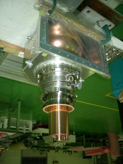
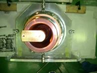
18 Energy-storage Cavity (S-cav) Q0(S-cav) =~ 1.7x10^5 Can store a large electromagnetic energy in TE013 To suppress the longitudinal CBIs Optimum detuning f = ω hω S-cav s R Isinφ = 2V c s 0 R Q Pb tanφs = 4πU a 0 f a Ua f a f = f = π a Ua + Us 1 + Us Ua f a f = 200 khz in KEKB/LER 2.6A, 20 sets a f a = 710 khz in SuperKEKB/LER 9.4A, 28 sets Cf. Ua :energy in A-cav Us :energy in S-cav =9 (in KEKB) f rev = 99kHZ Movable tuner on A-cav ~2m 17


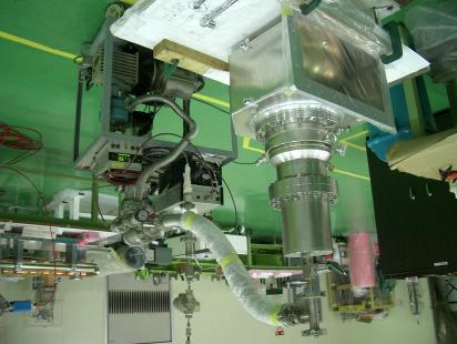
19 ARES in the KEKB Tunnel Design Parameters Vc Ra/Q0 Q0 Pin Pc Us/Ua 9 0.5MV 15 W 11x10^5 400kW 150kW (Waveguide from klystron) 18
 Beam current: ~1.")
 Total Vc = 15MV( 13MV) = 4.09MV(ARES)+10.91MV(SCC) (0.320~1.")
20 ARES Operation (Jan.~Feb, 2005) LER: 20 cavities Total Vc: 8.0MV (0.4MV/cav) Beam current: ~1.6A Input RF power/cav: ~300kW HOM power/cav: ~5kW Trip rate: ~1/cav/3months HER: 12 cavities (+ 8 SCCs) Total Vc = 15MV( 13MV) = 4.09MV(ARES)+10.91MV(SCC) (0.34MV/cav) Beam current: ~1.20~1.27A Trip rate (ARES): ~1/cav/3months Stable Operation!!! LER(e+) HER(e-) ARES cavities in the FUJI RF section 19


21 Upgrade toward 20
22 Main Strategy Make the beam size smaller: y* = 6 mm y* = 3 mm x2 Final focus magnets closer to Belle Tighter clearance More SR background Increase the beam-beam parameter by: ξ y = 0.05 ξ y = 0.14 Can be achieved by the successful Crab crossing Increase the beam currents: 2.6 A (LER) / 1.2 A (HER) 9.6 A (LER) / 4.1 A (HER) x3 x4 Target: cm sec x24 21
23 Measures against Larger detuning On ARES Increase the energy ratio: Us/Ua = Higher HOM powers HOM-load upgrade f f a π /2 = 1 +Us / Ua Higher input RF powers (400kW/cav 800kW/cav) TiN coating on the coaxial line Coupler test stand upgraded for ~800kW(CW) 22
24 ARES R&D Programs [1] Design modification of A-cav for Us/Ua: 9 15 [2] Construction of a new L-band HOM-load test stand Using 1.25GHz klystron (1.2MW, CW) The 1 st stage just finished [3] Input couplers with TiN coating Against multipactoring in the coaxial line TiN(Titanium Nitride) has low secondary-electron yields and is good for vacuum. Two couplers have been completed. Being tested in the upgraded coupler test stand up to 800kW. [4] New highly-pure copper electroplating for S-cav The old facility has been retired. Reusing a facility being used for J-PARC. 23
25 [1] To Change the Energy Ratio /2 mode & eq. circuit Applying Slater s tuning curve to the /2 mode Changing the aperture size: h btwn A-cav and C-cav, Us/Ua, Qext,s/Qext,a can be changed. 24
 2tan P = + P 1 RF 1 11 2 3 P1 frf Geometry A-cav C-cav")
26 Changing the Aperture Size of A-cav Simulation tool: HFSS S-parameter calculation The phase of the reflection coefficient: f P arg( S ) 2tan P = + P 1 RF P1 frf Geometry A-cav C-cav 25
27 Aperture Size v.s. Energy Ratio Modification of the aperture size: +15mm ( mm) for Us/Ua=15 Acceptable for the current mechanical structure Re-design of A-cav Aperture Size: h [mm] 26
28 Wall Loss in Energy-storage Cavity Pwall=150kW for Us/Ua=15 Record: Pwall>200kW in the teststand 27
29 Longitudinal Coupled-bunch Instability driven by the p/2 mode Larger detuning Larger instability driven by the accelerating /2 mode Cured by increasing the energy ratio: Us/Ua f f a π /2 = 1 + Us / Ua Impedance/cav of the p/2 Mode fa = 200kHz (in KEKB) fa = 710 khz (in SuperKEKB) Cf. f rev = 99kHZ We need the feedback? 28
30 Growth Rate(1) SuperKEKB LER ARES 28 sets 10 5 Ua : Us = 1 : 9, Vc = 0.5 MV (S. Yoshimoto) 10 4 Growth rate [1/s] µ = -1 µ = -2 µ =- 3 µ =- 4 Rad. damping rate Beam current [A] 29
31 Growth Rate(2) SuperKEKB LER ARES 28 sets Ua : Us = 1 : 15, Vc = 0.5 MV 10 5 (S. Yoshimoto) 10 4 Growth rate [1/s] µ = -1 µ = -2 µ =- 3 µ =- 4 Rad. damping rate Beam current [A] 30
32 Growth Rate(3) Ua : Us = 1 : 18, Vc = 0.5 MV SuperKEKB LER ARES 28 sets 10 5 (S. Yoshimoto) 10 4 Growth rate [1/s] µ = -1 µ = -2 µ =- 3 µ =- 4 Rad. damping rate Beam current [A] 31
33 Longitudinal Coupled-bunch Instability driven by the accelerating p/2 mode (SuperKEKB LER with 9.4A, ARES 28 sets, Vc=0.5MV/cav) Radiation damped Growth Time Can be suppressed by the upgraded RF feedback system using a comb filter (KEK-PREPRINT-96-79) 32
![[2] HOM-load](/docs-images/89/98760814/images/34-0.jpg "Upgrade ARES")

34 [2] HOM-load Upgrade ARES HOM-damped Structure HOM HOM HOM (Side view) 33
 In the Grooved Beam Pipe (GBP)")
 Max.")
35 SiC Absorbers In the HOM Wave Guide (WG) Direct water cooling Limit: >26kW/cav (HPT) In the Grooved Beam Pipe (GBP) Indirect water cooling via the copper plate Limit: ~3.6kW/cav (HPT) Max. power which can be supplied by the old L-band klystron. 34
36 HOM Extrapolation for Super-KEKB LER HOM in WG load (LER): 26kW/cav (HPT) 80kW/cav (SuperKEKB) Need HPTs over 26kW Increase # of absorbers /WG Enhanced water cooling (KEKB) Nb: 1224 σz: 7mm (Super-KEKB) 4896 (full) 3mm HOM in GBP load (LER): 3.6kW/cav (HPT) 20kW/cav (SuperKEKB) Need direct water cooling like in 35

37 Winged chamber loaded with SiC Absorbers (used in the movable-mask sections) Y. Suetsugu et al., Development of Winged HOM Damper for Movable Mask in KEKB, Proc. PAC2003. Can be a prototype. Directly water-cooled SiC bullet 36

38 New A-cav Design with Winged Chambers Directly water-cooled SiC bullet 37
39 We cannot test HOM loads with high powers for SuperKEKB. More powerful klystron is needed to upgrade the HOM loads. 38


40 D01C/ARES HOM-load Test Stand L-band klystron Freq. = 1.25GHz 1.2 MW (CW) Water dummy load Output from the klystron We would like to thank Fukuda-san and Hirano-san for their courtesy to allow us to use their klystron, RF windows and WG components. (Taken on ) 39

 Tuning to deliver more RF power")
41 The 1 st RF Power Comes! Output power beyond the max. obtained in the old L-band test stand (3.3kW) Tuning to deliver more RF power up to 100 kw 40
![[2] Input Couplers with TiN Coating The problem is the multipactoring in the coaxial line.](/docs-images/89/98760814/images/42-0.jpg "Coupling Loop Coaxial Line (WX77D) Example of the TV-camera snapshots of the multipactoring in the")
42 [2] Input Couplers with TiN Coating The problem is the multipactoring in the coaxial line. Coupling Loop Coaxial Line (WX77D) Example of the TV-camera snapshots of the multipactoring in the coaxial line 41


43 Studies on Total gas pressure Gas mixture ratio (Ar:N2) set Thickness meas. done by direct observation using SEM TiN coating Glass plate Secondary electron yields For the details, see the slides presented in the 6th Workshop on a Higher Luminosity B Factory: 42

44 Two input couplers have been TiN-coated with the final condition. (taken on ) 43


45 After Coating Before coating 44

46 Fabrication Leak test Tested in the upgrade coupler test stand 45


47 Coupler Test Stand Upgraded for Higher Power Capability: kW Input coupler used as output coupler S-cav Input coupler to be tested 1MW DL To 1- MW Water Dummy Load From 1- MW CW Klystron 46
48 Power History (Data taken in TS) To be compared with results on a coupler w/o TiN coating 47
![[4] New Copper Electroplating for S-cav S-cav is made from](/docs-images/89/98760814/images/49-0.jpg "Iron with copper electroplating. H. Ino, et.")
 Ex.")
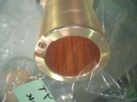
49 [4] New Copper Electroplating for S-cav S-cav is made from Iron with copper electroplating. H. Ino, et. al, "Advanced copper lining for accelerator components", Proc. of LAC2000, Monterey, CALIFORNIA, 1015 (2000) Ex. DTL tank for J-PARC Linac 48
50 Difference between J-PARC and SuperKEKB Studies on Thickness (targets) Ground(alkalinity): ~50µm Main(acidity): ~150µm Electrolytic Polishing: about -40µm Less defect Electric performance Check Q0. 49


 (Before")
51 Pillbox Test Cavity Diameter: 451.2mm Height: 260.0mm Made from iron (SS400) (After copper electroplating) (Before copper electroplating) 50
52 Theoretical Calculation of Q0 (=Q0(cal)) Analytical solution of the electromagnetic field in the pillbox cavity TEmnp mode Q0(m,n,p) = Assuming ω jωµ 0 m j' mn pπ z Er = A J ( )sin sin 2 m r mθ k r b d jωµ 0 j' mn j' mn pπ z Eθ = A J' ( )cos sin 2 m r mθ k b b d E = 0 1 pπ j' mn j' mn pπz Hr = A 2 J' m( r)cosmθ cos k d b b d 1 pπ m j ' pπz H = A J ( r)sinmθ cos mn 2 k d r m b d j ' mn pπ z Hz = AJm( r)cosmθ sin b d 100%IACS electric conductivity (=1/1.72E-8Ωm) flat surface (i.e. no defect) z θ mnp U P w a ll Wall loss power Stored energy P TMmnp mode U ε 2 dv E µ = = cavity 2 dv H cavity wall ωµ = 2 2σ cavity ds H 2 1 pπ j j pπz E = A J' ( r)cosmθ sin r mn mn 2 k d b m b d 1 pπ m j pπz E = A J ( r)sinmθ sin θ mn 2 k d r m b d jmn pπ z Ez = AJm( r)cosmθ cos b d jωε 0 m jmn pπ z Hr = A J ( )sin cos 2 m r mθ k r b d jωε 0 jmn jmn pπ z Hθ = A J' ( )cos cos 2 m r mθ k b b d H = 0 z 51
53 IACS International Annealed Copper Standard 100%IACS electric conductivity: 1/1.72E-8Ωm The electric conductivity of the highest-class oxygenfree copper: 102%IACS Cf. Electroplating in an acid sulfate bath w/o brightener: 102%IACS 52
54 53
55 54
56 After Trial and Error Copper Electroplating in an acid sulfate bath w/o brightener (PR process) Barrel Fine! Endcap 55
57 After Trial and Error Copper Electroplating in an acid sulfate bath w/o brightener (PR process) Barrel Fine! Electrolytic polishing Endcap 56


58 After Trial and Error Copper Electroplating in an acid sulfate bath w/o brightener (PR process) Barrel Fine! Electrolytic polishing Gorgeous! Endcap 57

59 Setup of the Q0 Measurement 58
 Loop")


60 Setup (close view) Loop couples with magnetic field. Antenna couples with electric field. 59
61 Results of the Q0 Measurements Electroplating in a pyrophosphate bath with brightener (applied to the present S-cav s) (no temperature correction) 60
62 Results of the Q0 Measurements DC electric conductivity (102%IACS) Frequency dependence comes from defects on the surface. TM modes TE modes Electroplating in an acid sulfate bath without brightener before electrolytic polishing Electroplating in a pyrophosphate bath with brightener (applied to the present S-cav s) (no temperature correction) 61
63 Results of the Q0 Measurements DC electric conductivity (102%IACS) No defect! Electroplating in an acid sulfate bath without brightener after electrolytic polishing Frequency dependence comes from defects on the surface. TM modes TE modes Electroplating in an acid sulfate bath without brightener before electrolytic polishing Electroplating in a pyrophosphate bath with brightener (applied to the present S-cav s) (no temperature correction) 62
64 Summary SuperKEKB is being proposed. The main strategy is To increase the beam-beam parameter, To make the beam size at IP smaller, To increase the beam currents. Every group is working hard! ARES R&D programs ongoing against higher beam currents For larger detuning, increase the energy ratio: Us/Ua: 9 15 HOM load upgrade with a new test stand. TiN-coated input coupler for the doubled input RF power (800kW, CW) Employing a new highly-pure copper electroplating for S-cav 63
65 (from K.Oide s review 2005) Official Goal Next Milestone Installation of Crab Cavity We are here. 550 /fb will be reached before the Crab Cavity. The next milestone (=1 /ab) will be achieved before Summer
66 (from K.Oide s review 2005) SuperKEKB Installation of Crab Cavity We are here. Shutdown Shutdown for months in for upgrade. 0.6 /ab/month in
67 Fin. 66
ARES Status 2004(JFY)
") ARES Status 2004(JFY) Tetsuo Abe for KEKB-RF/ARES-cavity group High Energy Accelerator Research Organization (KEK) Outline 1. Fundamentals of the ARES-cavity system 2. Operation status 3. D04C/ARES multipactoring
ARES Status 2004(JFY) Tetsuo Abe for KEKB-RF/ARES-cavity group High Energy Accelerator Research Organization (KEK) Outline 1. Fundamentals of the ARES-cavity system 2. Operation status 3. D04C/ARES multipactoring
PEP II Design Outline
 PEP II Design Outline Balša Terzić Jefferson Lab Collider Review Retreat, February 24, 2010 Outline General Information Parameter list (and evolution), initial design, upgrades Collider Ring Layout, insertions,
KEKB Accelerator Physics Report
 KEKB Accelerator Physics Report Y. Funakoshi for the KEKB commissioning group KEK, 1-1 Oho, Tsukuba, Ibaraki 305-0801,Japan Abstract 1 INTRODUCTION The KEKB B-Factory is an electron-positron double ring
ABORT DIAGNOSTICS AND ANALYSIS DURING KEKB OPERATION
 ABORT DIAGNOSTICS AND ANALYSIS DURING KEKB OPERATION H. Ikeda*, J. W. Flanagan, T. Furuya, M. Tobiyama, KEK, Tsukuba, Japan M. Tanaka, MELCO SC,Tsukuba, Japan Abstract KEKB has stopped since June 2010
PoS(EPS-HEP2015)525. The RF system for FCC-ee. A. Butterworth CERN 1211 Geneva 23, Switzerland
525. The RF system for FCC-ee. A. Butterworth CERN 1211 Geneva 23, Switzerland") CERN 1211 Geneva 23, Switzerland E-mail: andrew.butterworth@cern.ch O. Brunner CERN 1211 Geneva 23, Switzerland E-mail: olivier.brunner@cern.ch R. Calaga CERN 1211 Geneva 23, Switzerland E-mail: rama.calaga@cern.ch
CERN 1211 Geneva 23, Switzerland E-mail: andrew.butterworth@cern.ch O. Brunner CERN 1211 Geneva 23, Switzerland E-mail: olivier.brunner@cern.ch R. Calaga CERN 1211 Geneva 23, Switzerland E-mail: rama.calaga@cern.ch
PEP II STATUS AND PLANS *
 PEP II STATUS AND PLANS * John T. Seeman + Stanford Linear Accelerator Center, Stanford University, Stanford, CA 94309 USA The PEP II B-Factory 1 project is an e + e - colliding beam storage ring complex
Present Status and Future Upgrade of KEKB Injector Linac
 Present Status and Future Upgrade of KEKB Injector Linac Kazuro Furukawa, for e /e + Linac Group Present Status Upgrade in the Near Future R&D towards SuperKEKB 1 Machine Features Present Status and Future
!"!3
 Abstract A single-mode 500 MHz superconducting cavity cryomodule has been developed at Cornell for the electronpositron collider/synchrotron light source CESR. The Cornell B-cell cavity belongs to the
Status and Plans for PEP-II
 Status and Plans for PEP-II John Seeman SLAC Particle and Particle-Astrophysics DOE HEPAP P5 Review April 21, 2006 Topics Luminosity records for PEP-II in October 2005 Fall shut-down upgrades Run 5b turn
ANKA RF System - Upgrade Strategies
 ANKA RF System - Upgrade Strategies Vitali Judin ANKA Synchrotron Radiation Facility 2014-09 - 17 KIT University of the State Baden-Wuerttemberg and National Laboratory of the Helmholtz Association www.kit.edu
Production of quasi-monochromatic MeV photon in a synchrotron radiation facility
 Production of quasi-monochromatic MeV photon in a synchrotron radiation facility Presentation at University of Saskatchewan April 22-23, 2010 Yoshitaka Kawashima Brookhaven National Laboratory NSLS-II,
Detailed Design Report
 Detailed Design Report Chapter 4 MAX IV Injector 4.6. Acceleration MAX IV Facility CHAPTER 4.6. ACCELERATION 1(10) 4.6. Acceleration 4.6. Acceleration...2 4.6.1. RF Units... 2 4.6.2. Accelerator Units...
SuperTRISTAN. A possibility of ring collider for Higgs factory. 13 Feb K. Oide (KEK)
") A possibility of ring collider for Higgs factory 13 Feb. 2012 K. Oide (KEK) Inspired by A. Blondel and F. Zimmermann, A High Luminosity e+e- Collider in the LHC tunnel to study the Higgs Boson, V2.1 -
A possibility of ring collider for Higgs factory 13 Feb. 2012 K. Oide (KEK) Inspired by A. Blondel and F. Zimmermann, A High Luminosity e+e- Collider in the LHC tunnel to study the Higgs Boson, V2.1 -
Experience with the Cornell ERL Injector SRF Cryomodule during High Beam Current Operation
 Experience with the Cornell ERL Injector SRF Cryomodule during High Beam Current Operation Matthias Liepe Assistant Professor of Physics Cornell University Experience with the Cornell ERL Injector SRF
CONSTRUCTION AND COMMISSIONING OF BEPCII
 Abstract CONSTRUCTION AND COMMISSIONING OF BEPCII C. Zhang, J.Q. Wang, L. Ma and G.X.Pei for the BEPCII Team, IHEP, CAS P.O.Box 918, Beijing 100049, China BEPCII is the major upgrade of BEPC (Beijing Electron-
PEP-II STATUS REPORT *
 PEP-II STATUS REPORT * Jonathan Dorfan Stanford Linear Accelerator Center, Stanford University, Stanford, CA 94309 USA For the SLAC, LBNL, LLNL PEP-II group Abstract The main design features of the PEP-II
Linac upgrade plan using a C-band system for SuperKEKB
 Linac upgrade plan using a C-band system for SuperKEKB S. Fukuda, M. Akemono, M. Ikeda, T. Oogoe, T. Ohsawa, Y. Ogawa, K. Kakihara, H. Katagiri, T. Kamitani, M. Sato, T. Shidara, A. Shirakawa, T. Sugimura,
KEKB INJECTOR LINAC AND UPGRADE FOR SUPERKEKB
 KEKB INJECTOR LINAC AND UPGRADE FOR SUPERKEKB S. Michizono for the KEK electron/positron Injector Linac and the Linac Commissioning Group KEK KEKB injector linac Brief history of the KEK electron linac
DELIVERY RECORD. Location: Ibaraki, Japan
 DELIVERY RECORD Client: Japan Atomic Energy Agency (JAEA) High Energy Accelerator Research Organization (KEK) Facility: J-PARC (Japan Proton Accelerator Research Complex) Location: Ibaraki, Japan 1 October
PEP II Status and Plans
 SLAC-PUB-6854 September 1998 PEP II Status and Plans By John T. Seeman Invited talk presented at the 16th IEEE Particle Accelerator Conference (PAC 95) and International Conference on High Energy Accelerators,
A HIGH POWER LONG PULSE HIGH EFFICIENCY MULTI BEAM KLYSTRON
 A HIGH POWER LONG PULSE HIGH EFFICIENCY MULTI BEAM KLYSTRON A.Beunas and G. Faillon Thales Electron Devices, Vélizy, France S. Choroba DESY, Hamburg, Germany Abstract THALES ELECTRON DEVICES has developed
Upgrade of CEBAF to 12 GeV
 Upgrade of CEBAF to 12 GeV Leigh Harwood (for 12 GeV Accelerator team) Page 1 Outline Background High-level description Schedule Sub-system descriptions and status Summary Page 2 CEBAF Science Mission
Review of Diamond SR RF Operation and Upgrades
 Review of Diamond SR RF Operation and Upgrades Morten Jensen on behalf of Diamond Storage Ring RF Group Agenda Stats X-ray and LN2 pressure results Cavity Failure Conditioning in the RFTF Cavity Simulations
Bunch-by-bunch feedback and LLRF at ELSA
 Bunch-by-bunch feedback and LLRF at ELSA Dmitry Teytelman Dimtel, Inc., San Jose, CA, USA February 9, 2010 Outline 1 Feedback Feedback basics Coupled-bunch instabilities and feedback Beam and feedback
Experimental Results of the Coaxial Multipactor Experiment. T.P. Graves, B. LaBombard, S.J. Wukitch, I.H. Hutchinson PSFC-MIT
 Experimental Results of the Coaxial Multipactor Experiment T.P. Graves, B. LaBombard, S.J. Wukitch, I.H. Hutchinson PSFC-MIT Summary A multipactor discharge is a resonant condition for electrons in an
Basic rules for the design of RF Controls in High Intensity Proton Linacs. Particularities of proton linacs wrt electron linacs
 Basic rules Basic rules for the design of RF Controls in High Intensity Proton Linacs Particularities of proton linacs wrt electron linacs Non-zero synchronous phase needs reactive beam-loading compensation
First Simultaneous Top-up Operation of Three Different Rings in KEK Injector Linac
 First Simultaneous Top-up Operation of Three Different Rings in KEK Injector Linac Masanori Satoh (Acc. Lab., KEK) for the injector upgrade group 2010/9/16 1 Overview of Linac Beam Operation 2010/9/16
Status of SOLARIS. Paweł Borowiec On behalf of Solaris Team
 Status of SOLARIS Paweł Borowiec On behalf of Solaris Team e-mail: pawel.borowiec@uj.edu.pl XX ESLS-RF Meeting, Villingen 16-17.11.2016 Outline 1. Timeline 2. Injector 3. Storage ring 16-17.11.2016 XX
4.4 Injector Linear Accelerator
 4.4 Injector Linear Accelerator 100 MeV S-band linear accelerator based on the components already built for the S-Band Linear Collider Test Facility at DESY [1, 2] will be used as an injector for the CANDLE
Investigation of Radio Frequency Breakdown in Fusion Experiments
 Investigation of Radio Frequency Breakdown in Fusion Experiments T.P. Graves, S.J. Wukitch, I.H. Hutchinson MIT Plasma Science and Fusion Center APS-DPP October 2003 Albuquerque, NM Outline Multipactor
3 cerl. 3-1 cerl Overview. 3-2 High-brightness DC Photocathode Gun and Gun Test Beamline
 3 cerl 3-1 cerl Overview As described before, the aim of the cerl in the R&D program includes the development of critical components for the ERL, as well as the construction of a test accelerator. The
Dark current and multipacting trajectories simulations for the RF Photo Gun at PITZ
 Dark current and multipacting trajectories simulations for the RF Photo Gun at PITZ Introduction The PITZ RF Photo Gun Field simulations Dark current simulations Multipacting simulations Summary Igor Isaev
Status of BESSY II and berlinpro. Wolfgang Anders. Helmholtz-Zentrum Berlin for Materials and Energy (HZB) 20th ESLS-RF Meeting
 20th ESLS-RF Meeting") Status of BESSY II and berlinpro Wolfgang Anders Helmholtz-Zentrum Berlin for Materials and Energy (HZB) 20th ESLS-RF Meeting 16.-17.11.2016 at PSI Outline BESSY II Problems with circulators Landau cavity
Status of BESSY II and berlinpro Wolfgang Anders Helmholtz-Zentrum Berlin for Materials and Energy (HZB) 20th ESLS-RF Meeting 16.-17.11.2016 at PSI Outline BESSY II Problems with circulators Landau cavity
PEP-I1 RF Feedback System Simulation
 SLAC-PUB-10378 PEP-I1 RF Feedback System Simulation Richard Tighe SLAC A model containing the fundamental impedance of the PEP- = I1 cavity along with the longitudinal beam dynamics and feedback system
NSLS-II RF Systems James Rose, Radio Frequency Group Leader PAC 2011
 NSLS-II RF Systems James Rose, Radio Frequency Group Leader PAC 2011 1 BROOKHAVEN SCIENCE ASSOCIATES Introduction Linac RF cavities and klystrons Booster Cavity-Transmitter Storage Ring 500 MHz SRF cavity
Diamond RF Status (RF Activities at Daresbury) Mike Dykes
 Mike Dykes") Diamond RF Status (RF Activities at Daresbury) Mike Dykes ASTeC What is it? What does it do? Diamond Status Linac Booster RF Storage Ring RF Summary Content ASTeC ASTeC was formed in 2001 as a centre of
Diamond RF Status (RF Activities at Daresbury) Mike Dykes ASTeC What is it? What does it do? Diamond Status Linac Booster RF Storage Ring RF Summary Content ASTeC ASTeC was formed in 2001 as a centre of
Synchrotron Light Facility. Operation of ALBA RF. Angela Salom on behalf of RF team: Francis Perez, Bea Bravo and Jesus Ocampo
 Operation of ALBA RF Angela Salom on behalf of RF team: Francis Perez, Bea Bravo and Jesus Ocampo Outline ALBA RF Overview: Booster and SR RF Operation with beam Statistics of first year operation Cavities
PEP-II Status and Outlook
 PEP-II Status and Outlook H.-U. Wienands, M.E. Biagini, F.-J. Decker, M.H. Donald, S. Ecklund, A. Fisher, R.L. Holtzapple, R.H. Iverson, P. Krejcik, A.V. Kulikov, T. Meyer, J. Nelson, A. Novokhatski, I.
Mechanical aspects, FEA validation and geometry optimization
 RF Fingers for the new ESRF-EBS EBS storage ring The ESRF-EBS storage ring features new vacuum chamber profiles with reduced aperture. RF fingers are a key component to ensure good vacuum conditions and
The PEFP 20-MeV Proton Linear Accelerator
 Journal of the Korean Physical Society, Vol. 52, No. 3, March 2008, pp. 721726 Review Articles The PEFP 20-MeV Proton Linear Accelerator Y. S. Cho, H. J. Kwon, J. H. Jang, H. S. Kim, K. T. Seol, D. I.
North Damping Ring RF
 North Damping Ring RF North Damping Ring RF Outline Overview High Power RF HVPS Klystron & Klystron EPICS controls Cavities & Cavity Feedback SCP diagnostics & displays FACET-specific LLRF LLRF distribution
LEP Status and Performance in 2000
 LEP Status and Performance in 2 R. Assmann, SL/OP for the SL Division Outline: Operational strategy Overview on luminosity and energy performance Energy reach Luminosity performance Other issues Further
The Elettra Storage Ring and Top-Up Operation
 The Elettra Storage Ring and Top-Up Operation Emanuel Karantzoulis Past and Present Configurations 1994-2007 From 2008 5000 hours /year to the users 2010: Operations transition year Decay mode, 2 GeV (340mA)
RF considerations for SwissFEL
 RF considerations for H. Fitze in behalf of the PSI RF group Workshop on Compact X-Ray Free Electron Lasers 19.-21. July 2010, Shanghai Agenda Introduction RF-Gun Development C-band development Summary
The LEP Superconducting RF System
 The LEP Superconducting RF System K. Hübner* for the LEP RF Group CERN The basic components and the layout of the LEP rf system for the year 2000 are presented. The superconducting system consisted of
RF Power Generation II
 RF Power Generation II Klystrons, Magnetrons and Gyrotrons Professor R.G. Carter Engineering Department, Lancaster University, U.K. and The Cockcroft Institute of Accelerator Science and Technology Scope
Phase (deg) Phase (deg) Positive feedback, 317 ma. Negative feedback, 330 ma. jan2898/1638: beam pseudospectrum around 770*frev.
 Phase (deg) Positive feedback, 317 ma. Negative feedback, 330 ma. jan2898/1638: beam pseudospectrum around 770*frev.") Commissioning Experience from PEP-II HER Longitudinal Feedback 1 S. Prabhakar, D. Teytelman, J. Fox, A. Young, P. Corredoura, and R. Tighe Stanford Linear Accelerator Center, Stanford University, Stanford,
Commissioning Experience from PEP-II HER Longitudinal Feedback 1 S. Prabhakar, D. Teytelman, J. Fox, A. Young, P. Corredoura, and R. Tighe Stanford Linear Accelerator Center, Stanford University, Stanford,
OPERATIONAL EXPERIENCE AT J-PARC
 OPERATIONAL EXPERIENCE AT J-PARC Hideaki Hotchi, ) for J-PARC commissioning team ), 2), ) Japan Atomic Energy Agency (JAEA), Tokai, Naka, Ibaraki, 39-95 Japan, 2) High Energy Accelerator Research Organization
Operational Status of PF-Ring and PF-AR after the Earthquake
 Journal of Physics: Conference Series Operational Status of PF-Ring and PF-AR after the Earthquake To cite this article: T Honda et al 2013 J. Phys.: Conf. Ser. 425 042014 Related content - Design and
PRESENT STATUS OF J-PARC
 PRESENT STATUS OF J-PARC # F. Naito, KEK, Tsukuba, Japan Abstract Japan Proton Accelerator Research Complex (J-PARC) is the scientific facility with the high-intensity proton accelerator aiming to realize
THE NEXT LINEAR COLLIDER TEST ACCELERATOR: STATUS AND RESULTS * Abstract
 SLAC PUB 7246 June 996 THE NEXT LINEAR COLLIDER TEST ACCELERATOR: STATUS AND RESULTS * Ronald D. Ruth, SLAC, Stanford, CA, USA Abstract At SLAC, we are pursuing the design of a Next Linear Collider (NLC)
Upgrading LHC Luminosity
 1 Upgrading LHC Luminosity 2 Luminosity (cm -2 s -1 ) Present (2011) ~2 x10 33 Beam intensity @ injection (*) Nominal (2015?) 1 x 10 34 1.1 x10 11 Upgraded (2021?) ~5 x10 34 ~2.4 x10 11 (*) protons per
LEP OPERATION AND PERFORMANCE WITH ELECTRON-POSITRON COLLISIONS AT 209 GEV
 LEP OPERATION AND PERFORMANCE WITH ELECTRON-POSITRON COLLISIONS AT 29 GEV R. W. Aßmann, CERN, Geneva, Switzerland Abstract The Large Electron-Positron Collider (LEP) at CERN completed its operation in
RF plans for ESS. Morten Jensen. ESLS-RF 2013 Berlin
 RF plans for ESS Morten Jensen ESLS-RF 2013 Berlin Overview The European Spallation Source (ESS) will house the most powerful proton linac ever built. The average beam power will be 5 MW which is five
Spear3 RF System Sam Park 11/06/2003. Spear3 RF System. High Power Components Operation and Control. RF Requirement.
 Spear3 RF System RF Requirement Overall System High Power Components Operation and Control SPEAR 3 History 1996 Low emittance lattices explored 1996 SPEAR 3 proposed 11/97 SPEAR 3 design study team formed
New Filling Pattern for SLS-FEMTO
 SLS-TME-TA-2009-0317 July 14, 2009 New Filling Pattern for SLS-FEMTO Natalia Prado de Abreu, Paul Beaud, Gerhard Ingold and Andreas Streun Paul Scherrer Institut, CH-5232 Villigen PSI, Switzerland A new
CLIC Feasibility Demonstration at CTF3
 CLIC Feasibility Demonstration at CTF3 Roger Ruber Uppsala University, Sweden, for the CLIC/CTF3 Collaboration http://cern.ch/clic-study LINAC 10 MO303 13 Sep 2010 The Key to CLIC Efficiency NC Linac for
Status of Elettra, top-up and other upgrades
 Status of Elettra, top-up and other upgrades Emanuel Karantzoulis ELETTRA / Trieste, Italy / 2010 November 25-26 Past and Present Configurations 1994-2007 From 2008 No full energy injection Full energy
reported by T. Shintake KEK / RIKEN Japan Summary of C-band R&D for Linear Collider at KEK New soft-x-ray FEL Project at RIKEN/SPring-8
 C-band RF System R&D reported by T. Shintake KEK / RIKEN Japan Summary of C-band R&D for Linear Collider at KEK New soft-x-ray FEL Project at RIKEN/SPring-8 Project was funded in 2001 April Material Science
SUMMARY OF THE ILC R&D AND DESIGN
 SUMMARY OF THE ILC R&D AND DESIGN B. C. Barish, California Institute of Technology, USA Abstract The International Linear Collider (ILC) is a linear electron-positron collider based on 1.3 GHz superconducting
RF Upgrades & Experience At JLab. Rick Nelson
 RF Upgrades & Experience At JLab Rick Nelson Outline Background: CEBAF / Jefferson Lab History, upgrade requirements & decisions Progress & problems along the way Present status Future directions & concerns
FIRST SIMULTANEOUS TOP-UP OPERATION OF THREE DIFFERENT RINGS IN KEK INJECTOR LINAC
 FIRST SIMULTANEOUS TOP-UP OPERATION OF THREE DIFFERENT RINGS IN KEK INJECTOR LINAC M. Satoh #, for the IUC * Accelerator Laboratory, High Energy Accelerator Research Organization (KEK) 1-1 Oho, Tsukuba,
Precision measurements of beam current, position and phase for an e+e- linear collider
 Precision measurements of beam current, position and phase for an e+e- linear collider R. Corsini on behalf of H. Braun, M. Gasior, S. Livesley, P. Odier, J. Sladen, L. Soby INTRODUCTION Commissioning
STATUS OF THE SWISSFEL C-BAND LINEAR ACCELERATOR
 Proceedings of FEL213, New York, NY, USA STATUS OF THE SWISSFEL C-BAND LINEAR ACCELERATOR F. Loehl, J. Alex, H. Blumer, M. Bopp, H. Braun, A. Citterio, U. Ellenberger, H. Fitze, H. Joehri, T. Kleeb, L.
DESIGN OF 1.2-GEV SCL AS NEW INJECTOR FOR THE BNL AGS*
 DESIGN OF 1.2-GEV SCL AS NEW INJECTOR FOR THE BNL AGS* A. G. Ruggiero, J. Alessi, M. Harrison, M. Iarocci, T. Nehring, D. Raparia, T. Roser, J. Tuozzolo, W. Weng. Brookhaven National Laboratory, PO Box
Future Circular Collider Study
 Status and Progress M. Benedikt, F. Zimmermann gratefully acknowledging input from FCC coordination group global design study team and all other contributors LHC SPS PS FCC http://cern.ch/fcc Work supported
RF Design of the LCLS Gun C.Limborg, Z.Li, L.Xiao, J.F. Schmerge, D.Dowell, S.Gierman, E.Bong, S.Gilevich February 9, 2005
 RF Design of the LCLS Gun C.Limborg, Z.Li, L.Xiao, J.F. Schmerge, D.Dowell, S.Gierman, E.Bong, S.Gilevich February 9, 2005 Summary Final dimensions for the LCLS RF gun are described. This gun, referred
Status of CTF3. G.Geschonke CERN, AB
 Status of CTF3 G.Geschonke CERN, AB CTF3 layout CTF3 - Test of Drive Beam Generation, Acceleration & RF Multiplication by a factor 10 Drive Beam Injector ~ 50 m 3.5 A - 2100 b of 2.33 nc 150 MeV - 1.4
Pulsed Klystrons for Next Generation Neutron Sources Edward L. Eisen - CPI, Inc. Palo Alto, CA, USA
 Pulsed Klystrons for Next Generation Neutron Sources Edward L. Eisen - CPI, Inc. Palo Alto, CA, USA Abstract The U.S. Department of Energy (DOE) Office of Science has funded the construction of a new accelerator-based
Digital BPMs and Orbit Feedback Systems
 Digital BPMs and Orbit Feedback Systems, M. Böge, M. Dehler, B. Keil, P. Pollet, V. Schlott Outline stability requirements at SLS storage ring digital beam position monitors (DBPM) SLS global fast orbit
Trigger-timing signal distribution system for the KEK electron/positron injector linac
 Trigger-timing signal distribution system for the KEK electron/positron injector linac T. Suwada, 1 K. Furukawa, N. Kamikubota, and M. Satoh, Accelerator Laboratory, High Energy Accelerator Research Organization
SPEAR 3: Operations Update and Impact of Top-Off Injection
 SPEAR 3: Operations Update and Impact of Top-Off Injection R. Hettel for the SSRL ASD 2005 SSRL Users Meeting October 18, 2005 SPEAR 3 Operations Update and Development Plans Highlights of 2005 SPEAR 3
High Brightness Injector Development and ERL Planning at Cornell. Charlie Sinclair Cornell University Laboratory for Elementary-Particle Physics
 High Brightness Injector Development and ERL Planning at Cornell Charlie Sinclair Cornell University Laboratory for Elementary-Particle Physics June 22, 2006 JLab CASA Seminar 2 Background During 2000-2001,
A HIGH-POWER SUPERCONDUCTING H - LINAC (SPL) AT CERN
 AT CERN") A HIGH-POWER SUPERCONDUCTING H - LINAC (SPL) AT CERN E. Chiaveri, CERN, Geneva, Switzerland Abstract The conceptual design of a superconducting H - linear accelerator at CERN for a beam energy of 2.2 GeV
A HIGH-POWER SUPERCONDUCTING H - LINAC (SPL) AT CERN E. Chiaveri, CERN, Geneva, Switzerland Abstract The conceptual design of a superconducting H - linear accelerator at CERN for a beam energy of 2.2 GeV
Summary of the 1 st Beam Line Review Meeting Injector ( )
") Summary of the 1 st Beam Line Review Meeting Injector (23.10.2006) 15.11.2006 Review the status of: beam dynamics understanding and simulations completeness of beam line description conceptual design of
Summary of the 1 st Beam Line Review Meeting Injector (23.10.2006) 15.11.2006 Review the status of: beam dynamics understanding and simulations completeness of beam line description conceptual design of
BUNCH BY BUNCH FEEDBACK SYSTEMS FOR SUPERKEKB RINGS
 August 8-1, 216, Chiba, Japan PASJ216 TUOM6 BUNCH BY BUNCH FEEDBACK SYSTEMS FOR SUPERKEKB RINGS Makoto Tobiyama, John W. Flanagan, KEK Accelerator Laboratory, 1-1 Oho, Tsukuba 35-81, Japan, and Graduate
30 GHz Power Production / Beam Line
 30 GHz Power Production / Beam Line Motivation & Requirements Layout Power mode operation vs. nominal parameters Beam optics Achieved performance Problems Beam phase switch for 30 GHz pulse compression
45 MW, 22.8 GHz Second-Harmonic Multiplier for High-Gradient Tests*
 US High Gradient Research Collaboration Workshop. SLAC, May 23-25, 2007 45 MW, 22.8 GHz Second-Harmonic Multiplier for High-Gradient Tests* V.P. Yakovlev 1, S.Yu. Kazakov 1,2, and J.L. Hirshfield 1,3 1
News from HZB / BESSY Wolfgang Anders at ESLS-RF Meeting September 2010 Trieste
 News from HZB / BESSY Wolfgang Anders at ESLS-RF Meeting September 2010 Trieste Outline Status Klystrons / IOT Modifications of transmitters New LINAC for BESSY II Status BERLinPro HoBiCaT Extension --
Modeling and simulation of longitudinal dynamics for Low Energy Ring-High Energy Ring at the Positron-Electron Project 1
 SLAC-PUB-12374 February, 27 Modeling and simulation of longitudinal dynamics for Low Energy Ring-High Energy Ring at the Positron-Electron Project 1 C. Rivetta, T. Mastorides, J. D. Fox, D. Teytelman,
The ESS Accelerator. For Norwegian Industry and Research. Oslo, 24 Sept Håkan Danared Deputy Head Accelerator Division Group Leader Beam Physics
 The ESS Accelerator For Norwegian Industry and Research Oslo, 24 Sept 2013 Håkan Danared Deputy Head Accelerator Division Group Leader Beam Physics The Hadron Intensity Frontier Courtesy of M. Seidel (PSI)
LHC Beam Instrumentation Further Discussion
 LHC Beam Instrumentation Further Discussion LHC Machine Advisory Committee 9 th December 2005 Rhodri Jones (CERN AB/BDI) Possible Discussion Topics Open Questions Tune measurement base band tune & 50Hz
Introduction: CW SRF linac types, requirements and challenges High power RF system architecture
 RF systems for CW SRF linacs S. Belomestnykh Cornell University Laboratory for Elementary-Particle Physics LINAC08, Victoria, Canada October 1, 2008 Outline L band Introduction: CW SRF linac types, requirements
STATUS OF THE INTERNATIONAL LINEAR COLLIDER
 STATUS OF THE INTERNATIONAL LINEAR COLLIDER K. Yokoya, KEK, Tsukuba, Japan Abstract The International Linear Collider (ILC) is the nextgeneration electron-positron collider. Since the publication of the
Accelerator Instrumentation RD. Monday, July 14, 2003 Marc Ross
 Monday, Marc Ross Linear Collider RD Most RD funds address the most serious cost driver energy The most serious impact of the late technology choice is the failure to adequately address luminosity RD issues
PEP-II Overview & Ramp Down Plan. J. Seeman DOE PEP-II Ramp Down-D&D Review August 6-7, 2007
 PEP-II Overview & Ramp Down Plan J. Seeman DOE PEP-II Ramp Down-D&D Review August 6-7, 2007 Topics Overview of the PEP-II Collider PEP-II turns off September 30, 2008. General list of components and buildings
Non-Invasive Energy Spread Monitoring for the JLAB Experimental Program via Synchrotron Light Interferometers
 Non-Invasive for the JLAB Experimental Program via Synchrotron Light Interferometers P. Chevtsov, T. Day, A.P. Freyberger, R. Hicks Jefferson Lab J.-C. Denard Synchrotron SOLEIL 20th March 2005 1. Energy
Status of SOLARIS Arkadiusz Kisiel
 Status of SOLARIS Arkadiusz Kisiel Solaris National Synchrotron Light Source Jagiellonian University Czerwone Maki 98 30-392 Kraków www.synchrotron.uj.edu.pl Arkadiusz.Kisiel@uj.edu.pl On behalf of SOLARIS
Evaluation of Performance, Reliability, and Risk for High Peak Power RF Sources from S-band through X-band for Advanced Accelerator Applications
 Evaluation of Performance, Reliability, and Risk for High Peak Power RF Sources from S-band through X-band for Advanced Accelerator Applications Michael V. Fazio C. Adolphsen, A. Jensen, C. Pearson, D.
P. Emma, et al. LCLS Operations Lectures
 P. Emma, et al. LCLS Operations Lectures LCLS 1 LCLS Accelerator Schematic 6 MeV 135 MeV 250 MeV σ z 0.83 mm σ z 0.83 mm σ z 0.19 mm σ δ 0.05 % σ δ 0.10 % σ δ 1.6 % Linac-0 L =6 m rf gun L0-a,b Linac-1
2 Work Package and Work Unit descriptions. 2.8 WP8: RF Systems (R. Ruber, Uppsala)
") 2 Work Package and Work Unit descriptions 2.8 WP8: RF Systems (R. Ruber, Uppsala) The RF systems work package (WP) addresses the design and development of the RF power generation, control and distribution
2 Work Package and Work Unit descriptions 2.8 WP8: RF Systems (R. Ruber, Uppsala) The RF systems work package (WP) addresses the design and development of the RF power generation, control and distribution
Concept and R&D Plans for Project X
 Concept and R&D Plans for Project X Giorgio Apollinari 9 th ICFA Seminar SLAC, Oct. 2008 HB2008 Project X for Intensity Frontier Physics 1 Introduction Intensity Frontier: Needs and Physics Justification
Current status of XFEL/SPring-8 project and SCSS test accelerator
 Current status of XFEL/SPring-8 project and SCSS test accelerator Takahiro Inagaki for XFEL project in SPring-8 inagaki@spring8.or.jp Outline (1) Introduction (2) Key technology for compactness (3) Key
DESIGN AND PERFORMANCE OF L-BAND AND S-BAND MULTI BEAM KLYSTRONS
 DESIGN AND PERFORMANCE OF L-BAND AND S-BAND MULTI BEAM KLYSTRONS Y. H. Chin, KEK, Tsukuba, Japan. Abstract Recently, there has been a rising international interest in multi-beam klystrons (MBK) in the
TRANSVERSE DAMPING AND FAST INSTABILITIES
 TRANSVERSE DAMPING AND FAST INSTABILITIES Abstract The characteristics of the LHC beams in the SPS, protons and ions, pose stringent requirements on the SPS damper (feedback system). The boundary conditions
ILC-LNF TECHNICAL NOTE
 IL-LNF EHNIAL NOE Divisione Acceleratori Frascati, July 4, 2006 Note: IL-LNF-001 RF SYSEM FOR HE IL DAMPING RINGS R. Boni, INFN-LNF, Frascati, Italy G. avallari, ERN, Geneva, Switzerland Introduction For
DESIGN AND TECHNOLOGICAL ASPECTS OF KLYSTRON DEVELOPMENT
 DESIGN AND TECHNOLOGICAL ASPECTS OF KLYSTRON DEVELOPMENT Dr. L M Joshi Emeritus Scientist CSIR-CEERI, PILANI lmj1953@gmail.com 22 February 2017 IPR 1 Schemetic Diagram 22 February 2017 IPR 2 Basic Principle
Oak Ridge Spallation Neutron Source Proton Power Upgrade Project and Second Target Station Project
 Oak Ridge Spallation Neutron Source Proton Power Upgrade Project and Second Target Station Project Workshop on the future and next generation capabilities of accelerator driven neutron and muon sources
The Construction Status of CSNS Linac
 The Construction Status of CSNS Linac Sheng Wang Dongguan branch, Institute of High Energy Physics, CAS Sep.2, 2014, Geneva Outline The introduction to CSNS accelerators The commissoning of ion source
Design and Simulation of High Power RF Modulated Triode Electron Gun. A. Poursaleh
 Design and Simulation of High Power RF Modulated Triode Electron Gun A. Poursaleh National Academy of Sciences of Armenia, Institute of Radio Physics & Electronics, Yerevan, Armenia poursaleh83@yahoo.com