GUIDELINES FOR CABLE LAYING (PEM ELECTRICAL)
|
|
|
- Madeline Wilson
- 5 years ago
- Views:
Transcription

1 GUIDELINES FOR CABLE LAYING (PEM ELECTRICAL) DOCUMENT NUMBER: PE-GL E002, Rev. 00 ISSUE DATE: BHARAT HEAVY ELECTRICALS LIMITED POWER SECTOR PROJECT ENGINEERING MANAGEMENT NOIDA
 ). The above activity includes detailedd interfacee with BHEL Units for cable layouts to various load centers.")
2 PREFACEE BHEL PEM being the core engineering group forr EPC projects owning the responsibility for developing the cable trays network & providing the cable routing for complete power station (except the island of ESP Area being developed by BHEL-Ranipet) ). The above activity includes detailedd interfacee with BHEL Units for cable layouts to various load centers. The same is normallyy developed by BHEL PEM-Electrical taking care of the optimization, cost & plant esthetics & ergonomics factors. Further the cable routing being carried out by BHEL PEM Electricall through software for PEM Electrical / C& &I / MAX package Cable Schedules along with BHEL unit Cable schedules. Finally Routed Cable Schedules are forwarded to site for laying of various cables in installed cable trays. Off late it has been felt that in orderr to facilitate BHEL Site for better cable laying, an informative document for cable Laying, dressing, clamping etc. is required to be generated as general good practices to be followed by BHEL site through Site Cabling Contractor. This document has been prepared keeping in mind the above approach and for onward sending to all Power Sector Regions for their further use during cable laying through cabling contractor & furtherr feedbackk (if any).
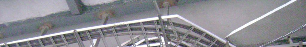
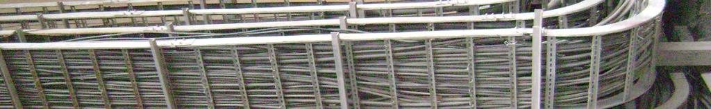
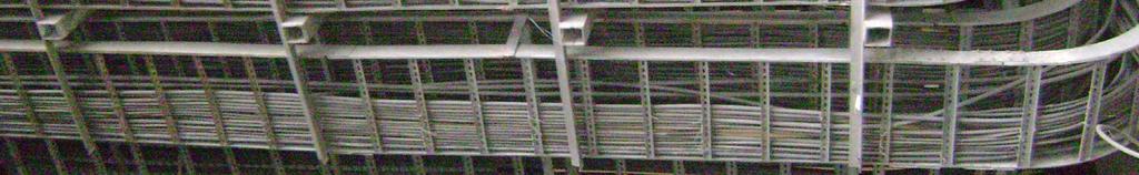
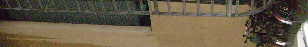
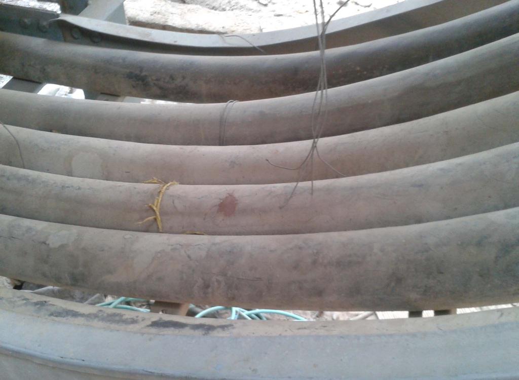
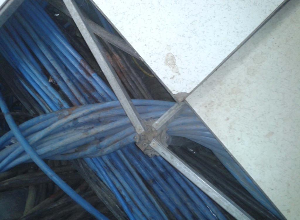
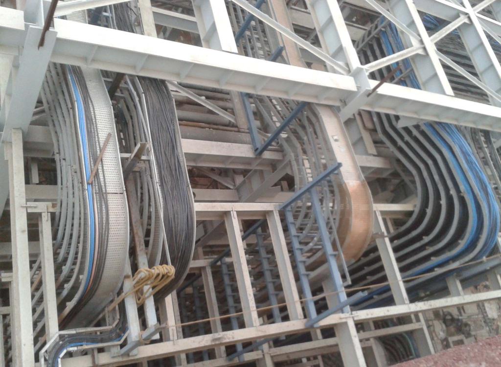
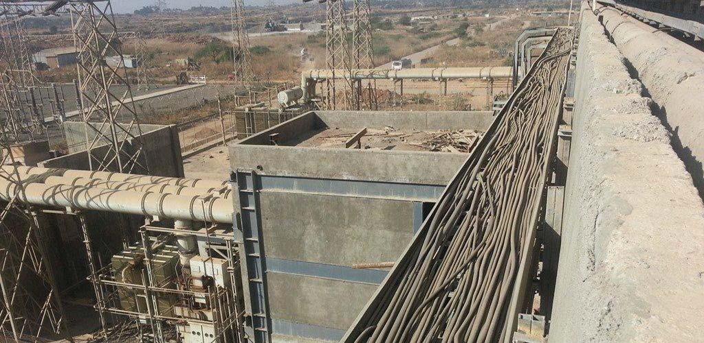
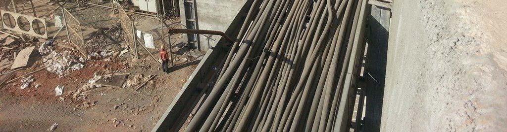
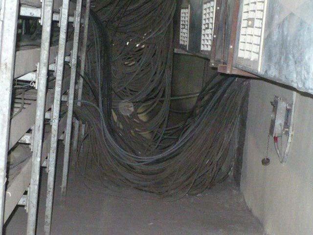
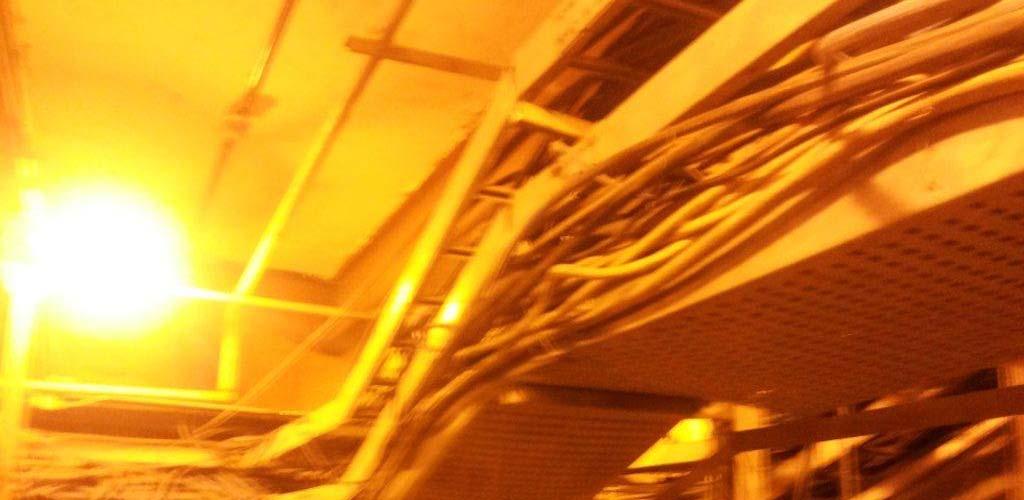
3 CONTENTS 1.0 GENERAL PHILOSOPHY 2.0 CABLE ROUTING IN CABLE TRENCHES/TRESTLES 3.0 CABLE ROUTING IN SPREADER R/FALSE FLOOR 3.1 SKETCH-1 & 2 SHOWING TYPICAL ARRANGEMENT BELOW FALSE FLOOR 4.0 CABLE ROUTING IN CABLE VAULT 5.0 SPECIAL PRECAUTIONS TO BE TAKEN WHILE LAYING OF CABLES 6.0 PHOTOGRA APHS SHOWING GOOD / BAD CABLING
4 1. General Philosophy for laying of different type of cables 1.1 Laying and installation of power, control and special cables shall generally conform to IS : Cable trays shall be routed as per various cable trayy layouts and further cables shall be routed as per the latest revision of routed cable schedules furnished by PEM. Site must check the latest revision of cable tray layouts & cable schedules before starting of cable routing. 1.3 Cable trays route numbering shall be painted / marked on all erected cable trays as per latest cable trays layout furnished by PEM before start of cable laying. 1.4 Proper care shall be taken for dressing the cables. While laying the cables, dressing shall be done after each run of cable. It is not advisable to dress the cable after laying all the cables. The cables shall be held in the trays temporarily by binding wire and shall be clamped finally with nylon ties. 1.5 At bends, large size cables (95sq.mm. & above) shall be laid in the outer edge of the bends to provide space for cable to bend. Smaller size cables shall be laid in the inner bend. 1.6 Jumping of cables between trays with no tray connection between them e.g. from horizontal to vertical connection, cables could be supported on angle or site fabricated support. 1.7 Where cabling passes through brickwork or concrete work, mechanical damage shall be provided. suitable local protection against 1.8 For cable trays which are closely placed, inter connection with tray accessories is not possible, site to fabricate connection from straight trays locally. 1.9 Each cable shalll be provided with identification tags indicating the cable numbers in accordance with the cable schedule. Cables shall be tagged at their entrance at every 30 m and exit from any equipment, junction box. The tags shall be of Aluminium with number punched on it and securely attached to the cable. The location of cable joints,, if any, shall be clearly indicated with cable marker with an additional inscriptions "Cable joint" and "Cable Number" Single core cables for a. c. three phase circuits, when laid on trays, shall be in trefoil formation (each trefoil with RYB phases formation), with eachh trefoil twice the diameter of cable apart from the next trefoil in the tray. The trefoil formation shall be duly secured to the cable tray by means
5 of trefoil clamps of nonmagnetic material at every 1000mm interval Multi-core cables above 1100 V grade when laid clamped by means of cable ties. on trays, shall be in one layer, touching and 1.12 Control and instrumentationn cables shall be laid in multi layers, but not exceeding three layers in any section While power, control and instrumentat tion cables shall generally be laid in separate trays, low current carrying power cables (valve/ damper actuator powerr cables) may be laid along with control cables Generally cables shall be placed on trays on the basis of theirr types and horizontal formations: functions as under for a) b) c) d) HT cables: in the top tier(s). LT power cables: in the tray(s) below the HT cable trays. Control cables: in the tray(s) next below to thee LT power cable tray(s) ). Instrumentation cables (screened control cables): in the bottom most tray(s). HT Power, LT Power and LT Control/Instrumentation cables shall be separated from each other by at least 250mm For vertical formations, the outermost tray shall bee considered as the topmost tray. In rare cases, where there is no clear distinction of bottom/ topp trays, the order convenient for linking the horizontal and vertical formations avoiding criss-crossing, or exit of cables shall be followed.
6 Typical examples of tray numbering are given below: L1 L2 L3 R1 R2 R DOUBLE SIDEDD TRAY (HORIZONTAL RUN) SINGLE SIDED TRAY (HORIZONTAL RUN) SINGLE SIDED TRAY (VERTICAL RUN) SINGLE SIDED TRAY (VERTICAL RUN) SINGLE SIDED TRAY (VERTICAL RUN) HORIZONTAL TRAY VERTICAL RISER ALONG WALL WALL EXAMPLE OF CHANGE OF NUMBERING SCHEME FOR ENSURING LEVEL CONTINUITY 1.16 Wherever it is not possible to accommodate cables as per the criteria indicated in the above clauses (due to layout constraints) for very short field runs, control cables may be laid in the same tray with the instrumentation cables with clear minimumm gap of 100mm between the two types of cables To facilitate pulling of cables in GI conduits, powdered soft stone, plastic soap or other dry inert lubricant may be used. However any material harmful to the cable sheaths shall not be used No single core cable shall pass throughh a GI conduit/ pipe or duct singly except DC single core cables. AC single core cables shall pass through GI conduit/ pipe in trefoil formation only, or through PVC pipes. Conduit/pipe occupancy shall not exceed 40% of the conduit/pipe cross-
7 section area. Pipes/ conduits shall not be used in corrosive areas Wherever site routed is mentioned in cable schedules, cables route as per the above criteria, as directed by site Engineer. may be laid through the shortest 1.20 Reinforced concrete manhole shall be provided in the duct bank, where required, so that cable may be installed without exceeding allowable pulling tensions, cable sidewall pressures or bending radius Cable clamping spacing for cables laid in cable trays shall be generally as under: (a) Trefoil clamps: 1) Horizontal run spacing: 2) Vertical run spacing: 1000 mmm (max.) 1000 mmm (max.) (b) Other Clamps 1. Power cables of sizes indicated under (i) (ii) (iii) (iv) Single core cables: 185 sq mm (when not laid in trefoil formation- e.g. dc circuits) Two core cables: 120 sq mm Three core cables: 95 sq mmm or higher Three & half core cable: 95 sq mmm or higher Horizontal runs: Individually clamped at 5000 mmm Vertical runs: Individually clamped at 1000 mmm interval (max.) interval (max.) 2. Power cables of other sizes Horizontal runs: Vertical runs: Collectively clamped at 5000 mmm Collectively clamped at 1000 mm interval (max.) interval (max.) 3. Control Cables Horizontal runs: Vertical runs: Collectively clamped at 5000 mmm Collectively clamped at 1000 mmm interval (max.) interval (max.)
8 1.22 Clamp spacing for cables supported directly along structure/ ceiling shall be as under: a) b) c) Clamp spacing 1. In horizontal runs: mm (max.)) 2. In vertical runs: 750 mm (max.) Spacing between cables: 30 mm (min.) Supports shall also be provided at each bend. 2. Cable routing in cable trenches/trestles 2.1 For trenches with concrete covers, site to ensure that the concrete segment at load end should be provided with pipe for cable outlet. 2.2 Insert plates should be provided in cable 1.5/1.25/1.0m (for galvanizing tray support) for supporting cable trays for cable routing. 2.3 Wall cut-out or pipe should be providedd in cable trench wall for smooth passage of proper placement of trench cover and avoiding cutting of cables by trench covers. cables and 2.4 Cable should be trench. laid in duct bank/through wall opening while entering a building through cable 3. Cable routing in cable spreader/false floor: 3.1 Cables below spreader / false floor shall be laid providing cable trays / angles supported on stub columns providedd for supporting false floor. Route shall be identified & marked in the drawing to facilitate site to route the cables in proper manner. Routing shall be planned keeping in mind number of risers available for routing of incoming & outgoing cables in the room. This will avoid jumbling of cables & overloading on particular connecting cable riser. Pl. refer attached SKETCH- to avoid 1 & Alternatively cables below spreader false / floor mayy be routed tying together in bunches over crowding & spreading over the floor all around.
9 4. Cable routing in cable vaults/cellar: 4.1 Inside the cable vaults crossing of cables from onee horizontal raceway to another shall be done through the vertical cable trays supported from ceiling to avoid criss crossings in the horizontal raceways. 4.2 Inside the cable vaults, cross connections away from entry points are to be utilised first and then the cross connections near the entry points are too be utilised later. This is required to avoid jamming of the cable trays at entry points by the cables running in the crosss connections. 4.3 Cables should be lifted in the space available along the cable tray support for termination at panels for smooth passage of other cables. 5. Specific precautions to be taken while laying of cables: 5.1 All the cables should be properly laid in cable trays, dressed and clamped at the time of laying itself. For identification of cables aluminum tags at regular intervals through out the run of the cable shall be provided. 5.2 While laying the cable, a roller shall be temporarily installed at an appropriate place avoid any damage to the cable while releasing the cable from the drum. in order to 5.3 Temporarily laid cables should be removed from cable trays to avoid overloading. 5.4 Temporarily laid, dead, unutilized & damaged cables should be removed from cable trays to avoid over loading & relievee tray space. 5.5 Do not stretch the cable tight inside the tray or duct Single core cables for AC application should be laid in trefoil formation using supplied trefoil clamps & to fix them with cable trays with the help of hardwares. 5.7 Once the cables are laid, welding should always be avoided either directly on the tray or above the tray and the welding shall be prohibited. If absolutely necessary, steel sheet or any other nonflammable material shall be placed over the tray or the cover so that the cable will not get damaged. 5.8 The cables shalll be meggered before laying. Whilee laying cable the instrumentation cables shall not mix with power cables. Care shall be taken to avoid sharp bending and kinking of conductor
10 damaging insulation and stressing the cable beyondd the pulling force. Cable shall be protected at all times from mechanical damage. 5.9 No cables shall be laid in ducts or trenches where other services such as oil pipes, steam or water pipes are laid In case of deviation by site of erection of cable trayss w. r. t PEM drawings, intimation / discussion with PEM is required Trunk routes in case planned by site to be shared with PEM for proper planning & rectification All cable tray risers from control room / switchgear room designated for various system cablings. are to be marked with paint for 5.13 All over spilled cables outside cable trays are required proper dressing. pieces may be installed for accommodat tion of thosee cables. If required cable tray 5.14 Close co-ordination between site electrical cabling contractor and C& &I cabling required for cable laying. contractor
11
12


13

14


15
16
17
18
19
20

21
Bharat Heavy Electricals Limited HIGH PRESSURE BOILER PLANT, TIRUCHIRAPPALLI CONTROLS AND INSTRUMENTATION/FB
 Bharat Heavy Electricals Limited HIGH PRESSURE BOILER PLANT, TIRUCHIRAPPALLI 620 014. CONTROLS AND INSTRUMENTATION/FB DATA SHEET FOR MULTICORE, ARMOURED, CONTROL CABLE Project: Ennore Sez, 2 x 660 MW,
Cable installation guidelines
 The Quality Connection Cable installation guidelines Business Unit Industrial Projects 2 Cable installation guidelines www.leoni-industrial-projects.com GENERAL Installation methods Many different methods
ELECTRICAL SAFETY INSPECTION REPORT
 ELECTRICAL SAFETY INSPECTION REPORT A PLUS INDUSTRIES LIMITED. Plot-28, Milk Vita Rd., Section-07, Mirpur, Dhaka Factory List: 1. A Plus Industries Ltd. Inspected by: Yoon Report Generated by: Nezar Inspected
ELECTRICAL SAFETY INSPECTION REPORT. MTM Garments Ltd.
 ELECTRICAL SAFETY INSPECTION REPORT MTM Garments Ltd. 15934/16004, Chanpara, Medical Road, Uttarkhan, Dhaka, Bangladesh. Factory List MTM Garments Ltd. Inspected by: Hemlal Dahal Report Generated by: Hemlal
NC-1000 INSTALLATION MANUAL NC-1000 FIBRE OPTIC CROSS-CONNECTION SYSTEM
 NC-1000 INSTALLATION MANUAL NC-1000 FIBRE OPTIC CROSS-CONNECTION SYSTEM Content 1. General 5 2. The products of NC-1000 system 6 3. Mounting of the frame 8 4. Earthing of the frame 8 NC-1000 FIBRE OPTIC
Identification - electrical services
 Identification - electrical services Aesthetic All live phase cable sheathing to be brown coloured and neutral phase cable sheathing to be blue coloured, all labelled L1, L2, L3 & N respectively in accordance
High Voltage Cables kv. Handling and Operating Instructions
 High Voltage Cables 52 145 kv Handling and Operating Instructions 1 (24) HANDLING AND OPERATING DRYREX High voltage cables 52 145 kv Contents Scope of application...3 General...3 Professional skills, tools
ACADEMIC SUCCESS CENTER THE COLLEGE AT BROCKPORT STATE UNIVERSITY OF NEW YORK PROJECT NO
 SECTION 270536 - CABLE TRAYS FOR COMMUNICATIONS SYSTEMS PART 1 - GENERAL 1.1 RELATED DOCUMENTS A. Drawings and general provisions of the Contract, including General and Supplementary Conditions and Division
Tab 10 - The NESC and Underground Applications. Restricted Siemens Industry, Inc All rights reserved.
 Tab 10 - The NESC and Underground Applications Restricted Siemens Industry, Inc. 2017 All rights reserved. siemens.com/poweracademy The National Electric Safety Code (NESC) The NESC provides guidelines
ELECTRICAL SAFETY FOLLOW UP INSPECTION REPORT (8th) Factory Name Address Factory ID
 Factory Name Address Factory ID") Factory Name Address Factory ID Shirir Chala, Bagherbazar 11705 Electrical Safety dates Initial Date 09/07/2014 30/10/2016 Date of 5 th Follow Up Report Received Date 24/08/2014 02/01/2017 Date of 6 th
Factory Name Address Factory ID Shirir Chala, Bagherbazar 11705 Electrical Safety dates Initial Date 09/07/2014 30/10/2016 Date of 5 th Follow Up Report Received Date 24/08/2014 02/01/2017 Date of 6 th
Underground Installation of Optical Fiber Cable by Pulling
 Application Notes Underground Installation of Optical Fiber Cable by Pulling Authors Prasanna Pardeshi and Sudipta Bhaumik Issued July 2015 Abstract This application note discusses underground fiber optic
UNIVERSITY of NORTH DAKOTA LOW VOLTAGE COMMUNICATIONS STANDARDS FOR CABLING, PATHWAYS, AND SPACE
 UNIVERSITY of NORTH DAKOTA LOW VOLTAGE COMMUNICATIONS STANDARDS FOR CABLING, PATHWAYS, AND SPACE Prepared in cooperation and approval from BICSI Building Industry Consulting Services International and
SAQCC FIRE D&GS TRAINING SUB COMMITTEE COURSE CURRICULUM
 SAQCC FIRE D&GS TRAINING SUB COMMITTEE COURSE CURRICULUM COURSE ORIGINATOR Cabling and Conduit K Norgate DATE 23rd August 2013 Amendment 1 5th October 2013 Technical changes - Issued Amendment 2 6th October
UNIFIED FACILITIES GUIDE SPECIFICATIONS
 USACE / NAVFAC / AFCEC / NASA UFGS-27 05 14.00 10 (April 2006) -------------------------------- Preparing Activity: USACE Superseding UFGS-27 05 14.00 10 (April 2004) UNIFIED FACILITIES GUIDE SPECIFICATIONS
220KV EHV NETWORK AT RELIANCE JAMNAGAR REFINERY COMPLEX
 220KV EHV NETWORK AT RELIANCE JAMNAGAR REFINERY COMPLEX JAMNAGAR 220KV CABLE NETWORK: 2 2. DESIGN 2A. NETWORK: 220 KV NETWORK DESIGN IS DESIGNED WITH 100% REDUNDANCY FROM 220 KV BUS TO LOAD. THIS IS ACHIEVED
Minimum qualifications for the Telecommunications Engineer are: A. Texas Licensed Profession Engineer (PE)
") PART 1: GENERAL 1.01 Telecommunications Engineer Minimum qualifications for the Telecommunications Engineer are: A. Texas Licensed Profession Engineer (PE) B. Registered Communications Distribution Designer
PART 1: GENERAL 1.01 Telecommunications Engineer Minimum qualifications for the Telecommunications Engineer are: A. Texas Licensed Profession Engineer (PE) B. Registered Communications Distribution Designer
BILOXI PUBLIC SCHOOL DISTRICT. Biloxi Junior High School
 BILOXI PUBLIC SCHOOL DISTRICT Biloxi Junior High School Request for Proposals E-Rate 2014-2015 - Internal Connections Submit Proposals To: Purchasing Department Attn: Traci Barnett 160 St. Peter Street
ELECTRICAL SAFETY INSPECTION REPORT.
 ELECTRICAL SAFETY INSPECTION REPORT., Plot no: 72 & 82, DEPZ, Ganakbari, Savar, Dhaka, Bangladesh. Factory List: 1.Experience Clothing Company Ltd. Inspected on March 31, 2014 SUMMARY Experience Clothing
TERMINATIONS AND JOINTS FOR XLPE-INSULATED kv MEDIUM VOLTAGE CABLES
 Accessories TERMINATIONS AND JOINTS FOR XLPE-INSULATED 12 36 kv MEDIUM VOLTAGE CABLES Cable Systems, Cables and Accessories Test values for terminations 1) Testing to DIN VDE 0278-629-1 (Testing methods
IndyGo Facility Upgrades Project 35671EE
 SECTION 260553 IDENTIFICATION FOR ELECTRICAL SYSTEMS PART 1 - GENERAL 1.1 SUMMARY A. Section Includes: 1. Identification for raceways. 2. Identification of power and control cables. 3. Identification for
SECTION MEDIUM VOLTAGE CABLE INSTALLATION. 1. Section Underground Ducts and Manholes.
 SECTION 33 71 49.23 MEDIUM VOLTAGE CABLE INSTALLATION PART 1 GENERAL 1.1 SCOPE A. Work included in this Section: Medium Voltage Cable (4 kv and 12 kv) Installation and Termination. Removal and return of
Electrical Installation Booklet Shipyard Standards
 Marine Institute of Memorial University of Newfoundland Electrical Installation Booklet Shipyard Standards Marine Engineering Systems Design Department Revision 0 List of Revisions Revision Description
Sample Test Project. District / Zonal Skill Competitions. Skill- Electrical Installation. Category: Construction and Building Technology
 Sample Test Project District / Zonal Skill Competitions Skill- Electrical Installation Category: Construction and Building Technology Version 1 Dec 2017 Skill- Electrical Installation 1 Table of Contents
Instructions. Cable with Armor F CAUTION. October Rev A
 3M Single Conductor Accessory Breakout Kits (BOK's) for use with 3M Cable Accessories (Terminations, T-Bodies and Push-On Elbows) For Use With Single Conductor Accessories On Three-Core Conductor Cables
Field Instruction. Any registered training organisation UETTDRCJ21A Lay ESI electrical cables. Before commencing work:
 6.10 Cable Installation Purpose This field instruction outlines the minimum cable installation requirements for all Horizon Power Workers, including Workers operating, servicing, and/ or maintaining (MPS)
Student Services & Classroom Addition
 SECTION 260513 - MEDIUM-VOLTAGE CABLES PART 1 - GENERAL 1.1 SUMMARY A. Section includes cables and related cable splices, terminations, and accessories for mediumvoltage (2001 to 35,000 V) electrical distribution
SPECIAL SPECIFICATION 8540 Telecommunication Cable
 2004 Specifications CSJ 0914-00-307 & CSJ 0914-25-003 SPECIAL SPECIFICATION 8540 Telecommunication Cable 1. Description. This specification governs the materials, installation, termination, splicing, testing,
SWA Cable BS6724 Steel Wire Armoured LSZH Eland Product Group A9L
 SWA Cable BS6724 Steel Wire Armoured LSZH Eland Product Group A9L Application SWA Cable power and auxiliary control cables for use in power networks, underground, outdoor and indoor applications and for
Aerial Cable Installation Best Practices
 Aerial Cable Installation Best Practices Panduit Corp. 2007 BEST PRACTICES Table of Contents 1.0 General... 3 2.0 Introduction... 3 3.0 Precautions... 4 4.0 Pre-survey... 5 5.0 Materials and Equipment...
FIBER OPTIC CABLE PULLING
 C H A P T E R 15 FIBER OPTIC CABLE PULLING THOMAS A. DOOLEY AND JERALD R. ROUNDS (with hints from Northern Lights Cable) Electrical wire installers know how to pull cable. The basic approach to pulling
Installation Manual IPT Installation of skillet systems with 125 A track current. MV a-E.
 www.wampfler.com Page 1 of 27 Index Page 1 Basics...4 2 Basic understanding of an IPT -system...5 3 General rules regarding metal parts in close proximity...6 3.1 Envelope free of ferromagnetic material...6
Laying of cables and lines in electrical installations and data networks
 Technical bulletin Laying of cables and lines in electrical installations and data networks Date: 08/2006 This technical bulletin provides you with information on specific technical subjects. It is based
Channel Cable Tray - Accessories
 Splice Plate The Splice Plate has the standard 4-hole pattern for all cable channel. Provided with straight sections and fittings. 9(*)-1043 3 (76) 9(*)-1044 4 (101) 9(*)-1044-6 6 (152) Horizontal Adjustable
SPECIAL SPECIFICATION 6559 Telecommunication Cable
 2004 Specifications CSJ 0015-09-147, etc. SPECIAL SPECIFICATION 6559 Telecommunication Cable 1. Description. This specification governs the materials, installation, termination, splicing, testing, training,
PKK PKK CHARACTERISTICS. Dimensions. Travel. Travel speed. Acceleration. Temperature. Special versions APPLICATION AREAS. PLE max.
 PKK loa d / (kg/m) PKK 10 8 6 4 2 0 0 P KK 1 20 PKK applications 49 PKK dimensions 50 PKK types 52 PKK sizes 54 PKK parts 55 PKK assembly 56 PKK article numbers 62 LOAD DIAGRAM PKK 2 2 0 2 P KK 2 40 PKK
SWA Cable - BS5467 Steel Wire Armoured PVC Eland Product Group A9S
 SWA Cable - BS5467 Steel Wire Armoured PVC Eland Product Group A9S Application SWA Cable - power and auxiliary control cables for use in power networks, underground, outdoor and indoor applications and
Connecting cables NEBS, for sensors
 Connecting cables NEBS, for sensors Connecting cables NEBS, for sensors Product range overview Function Version Type code Connection technology (Electrical connection 2) Connecting cable Cable characteristic
VITALink Taped Splice Straight Through Crimp
 A Marmon Wire & Cable Berkshire Hathaway Company VITALink Taped Splice Straight Through Crimp 2 Hour Fire-Rated Splice VITALink MC Cables, UL FHIT 120 Installation Instructions Description The VITALink
SPECIFICATION FIBER OPTIC SPLICE CLOSURE. Spec No : VSS-1007-BS403A-04A/SD. VSS-0107-BS403A-04A/SD R & D Center Manufacturing Division
 SPECIFICATION FIBER OPTIC SPLICE CLOSURE Model Spec. No. Distribution Depts. VSOF-BS403A VSS-0107-BS403A-04A/SD R & D Center Manufacturing Division Sales Division Management Division Revision 10. 07 (Rev.4)
SITE All work shall be performed at Center Park Substation (1895 Kernan Blvd, Jacksonville, Fl ). DATE: 04/03/2018
. DATE: 04/03/2018") DATE: 04/03/2018 TO: The Contractor FROM: System Protection & Control Projects 20413 SUBJECT: Technical Specifications for Center Park APSTF Project PROJECT OVERVIEW This is a general specification that
DATE: 04/03/2018 TO: The Contractor FROM: System Protection & Control Projects 20413 SUBJECT: Technical Specifications for Center Park APSTF Project PROJECT OVERVIEW This is a general specification that
Connecting cables for valves, Sub-D Type codes
 Type codes NEBV C S1 G 44 K Function NEBV Connecting cables for valves Product design Standard C Easy to clean design Connection technology, left, field device side S1 S7 Sub-D socket Sub-D HD socket Cable
OCC Installation Conduit Guidelines Excerpt from Optical Cable Corporation s INSTALLATION GUIDE
 Installation Conduit Guidelines Excerpt from Optical Cable Corporation s INSTALLATION GUIDE Conduit Installation A conduit cable installation involves placement of one or more optical cables inside a preinstalled
Processing Specification MiniBridge IDC
 Processing Specification MiniBridge IDC ERNI Electronics GmbH & Co. KG Seestrasse 9 l 73099 Adelberg / Germany l +49 7166 50-0 l www.erni.com Version 5 IMS Verarbeitungsspezifikationen Seite 1 von 11 Table
CLT17620AVControlRoom-RA.doc Page 1 CENTER FOR LEARNING AND TECHNOLOGY - A/V PRODUCTION ROOM 104 CLT PROD ROOM.doc
 CLT17620AVControlRoom-RA.doc Page 1 CENTER FOR LEARNING AND TECHNOLOGY - A/V PRODUCTION ROOM 104 CLT PROD ROOM.doc The general consensus of the occupants of the CLT is that the following rooms be equiped
Section 8 FIBERLIGN Hardware for Aerial FTTP Applications
 Section FIBERLIGN Hardware for Aerial FTTP Applications Table of Contents Page FIBERLIGN Products for ADSS Applications FIBERLIGN ADSS Drop Cable Dead-end...-2 FIBERLIGN Midspan Drop...-5 FIBERLIGN LITE
TRANSMISSION ENGINEERING STANDARD TES-P , Rev. 0 TABLE OF CONTENTS 1.0 SCOPE 2.0 CABLES SPLICES
 1.0 SCOPE TABLE OF CONTENTS 2.0 CABLES SPLICES 2.1 Definitions 2.2 Scope of Specifications and Drawings 2.3 General Requirements 2.4 Routing Cables 2.5 Connectors 2.6 Conductor Connections 2.7 Heat Shrinkable
OCC Installation Round Messenger Guidelines Excerpt from Optical Cable Corporation s INSTALLATION GUIDE
 Installation Round Messenger Guidelines Excerpt from Optical Cable Corporation s INSTALLATION GUIDE Round Messenger (ADSS) A round messenger fiber optic cable is designed for use in aerial installations
HighBand 25. TrueNet Category 6 Solutions
 HighBand 25 TrueNet Category 6 Solutions The highest performing cross-connect system in the world. A unique high-density solution with superior cable management. ADC KRONE s HighBand 25 cross connect solution
Abhyudaya Marketing Solutions
 9553315000 Abhyudaya Marketing Solutions http://cabletraygratings.com/ Welcome to Abhyudaya Marketing Solutions We came into existence in the market, in the year 2014 with a name of Abhyudaya Marketing
Instrumentation Cables
 Instrumentation Cables 9 KEWBERG manufactures and supplies a wide range of Instrumentation cables, which are made using superior raw materials. These are extensively used in data acquisition systems, process
FIBRE OPTIC CABLE SOLUTIONS
 point2point FIBRE OPTIC CABLE SOLUTIONS Introduction From patch-leads through to cross-site cables, or optical adapters through to patch panels, PPM s one-stopshop approach to fibre optic cable management
For Sales & Information, Call Toll Free: (888)
") PCR Outline Dimensions 2.75" (69.8 mm) 0.44" (11 mm) 0.25" (6.3 mm) (-) (+) 15.8" (401 mm) 9.3" (236 mm) Nameplate 1.25" (31.8 mm) 3.0" (76 mm) 7.40" (188 mm) 12.63" (321 mm) R 0.219" (R 5.56 mm) Serial
PCR Outline Dimensions 2.75" (69.8 mm) 0.44" (11 mm) 0.25" (6.3 mm) (-) (+) 15.8" (401 mm) 9.3" (236 mm) Nameplate 1.25" (31.8 mm) 3.0" (76 mm) 7.40" (188 mm) 12.63" (321 mm) R 0.219" (R 5.56 mm) Serial
SJOF-BS604B. Fiber Optic Splice Closure User Manual Rev.1
 Fiber Optic Splice Closure 1. Introduction 1.1 General SAMJIN s SJOF-BS604B protects fiber optic splicing point in various installation conditions such as aerial, manholes, ducts, wall and direct buried
INSTRUCTION DE SÉCURITÉ SAFETY INSTRUCTION Mandatory as defined in SAPOCO/42 FIRE PREVENTION FOR CABLES, CABLE TRAYS AND CONDUITS
 CERN INSTRUCTION DE SÉCURITÉ SAFETY INSTRUCTION Mandatory as defined in SAPOCO/42 Edms 335813 TIS IS 48 Edited by: TIS/GS Publication Date: June 2001 Original: English FIRE PREVENTION FOR CABLES, CABLE
Effective earthing of screened cables
 NOVEMBER 2006 Effective earthing of screened cables All metallic containment items, other extraneous metalwork and the screens of telecommunications cables in an information technology environment must
Küba compact DF. The space-saving helper in filling stations, gastronomy and the trade
 The space-saving helper in filling stations, gastronomy and the trade The space-saving helper in the positive and negative range Straightforward mounting Integrated air baffle plate Extremely space-saving
TECHNICAL SPECIFICATION
 TECHNICAL SPECIFICATION (FIBER OPTIC SPLICE CLOSURE) Model Spec. No. Distribution Depts. VSOF-BS403A SJP-0609-403A-01A/SD Quality Assurance Team Manufacturing Division Sales Division Management Division
PKK PKK CHARACTERISTICS. Dimensions. Travel. Travel speed. Acceleration. Temperature. Special versions APPLICATION AREAS. PLE max.
 loa d / (kg/m) PKK inner height / (mm) 10 8 6 4 2 0 0 118 115 80 50 30 16 7 48 7 P KK 1 20 30 PKK applications 49 PKK dimensions 50 PKK types 52 PKK sizes 54 PKK parts 55 PKK assembly 56 PKK article numbers
COMMON WORK RESULTS FOR INTEGRATED AUTOMATION DESIGN AND CONSTRUCTION STANDARD
 PART 1: GENERAL 1.01 Purpose: A. This standard is intended to provide useful information to the Professional Service Provider (PSP) to establish a basis of design. The responsibility of the engineer is
INSTALLATION INSTRUCTIONS MO023A
 INSTALLATION INSTRUCTIONS MO023A Nexans N3S ODF system NEXANS N3S ODF SYSTEM Content Product description Patching frame Splice frame Doors Splice module Patch module Protective cover and label panel Guides
INSTALLATION INSTRUCTIONS
 LIGHTGUARD 350-20-WTC SEALED FIBER OPTIC CLOSURE VIEW ONLINE TABLE OF CONTENTS: GENERAL...2 SPECIFICATIONS...2 PACKAGE CONTENTS...3 PACKAGE CONTENTS: ACCESSORIES...3 RECOMMENDED TOOLS...3 ADD-ON COMPONENTS...4
ISS New Audio & Visual installations Design and Physical install guidelines v1.5
 ISS New Audio & Visual installations Design and Physical install guidelines v1.5 David Neal 11/05/2018 Contents Background... 3 Installation Standards... 3 Display Screen and Projector positioning... 3
The MTS FiON Network. for Multiple Dwelling Units (MDUs) Greenfield/Brownfield Renovations
 Greenfield/Brownfield Renovations") The MTS FiON Network for Multiple Dwelling Units (MDUs) Greenfield/Brownfield Renovations Table of Contents We ve Upgraded our Network... 1 MTS Fibre Optics Installation Guidelines... 2 MTS Fibre Optics
The MTS FiON Network for Multiple Dwelling Units (MDUs) Greenfield/Brownfield Renovations Table of Contents We ve Upgraded our Network... 1 MTS Fibre Optics Installation Guidelines... 2 MTS Fibre Optics
STRUCTURED CABLE SYSTEM (SCS)
") PART 1 GENERAL 1.01 DESCRIPTION A. The work covered by this section of the Specifications includes all labor necessary to perform and complete such construction, all materials and equipment incorporated
PART 1 GENERAL 1.01 DESCRIPTION A. The work covered by this section of the Specifications includes all labor necessary to perform and complete such construction, all materials and equipment incorporated
Compact Module. Category 6 FTP Cabling System
 Compact Module Shielded design for improved EMI performance Suitable for Gigabit Ethernet applications and beyond Ultra-slimline design Colour coded for quick and accurate termination Interchangeable with
LANmark PCB patch panel, 1HU INSTALLATION GUIDE. LANmark PCB patch panel, 1 HU
 LANmark PCB patch panel, 1HU INSTALLATION GUIDE LANmark PCB patch panel, 1 HU Document information Document reference Release September 2001 Published by Contact address BRO-009 LANmark PP 1HU 0701 Nexans
Cambria County Association for the Blind and Handicapped 175 Industrial Park Road Ebensburg, PA Prepared for: Prepared by:
 Cable Management in Solar PV Arrays: A Review of Requirements in the National Electrical Code and how CAB Cable Rings and Saddles Meet These Requirements Prepared for: Cambria County Association for the
NORTHWESTERN UNIVERSITY PROJECT NAME JOB # ISSUED: 03/29/2017
 SECTION 26 0553 - IDENTIFICATION FOR ELECTRICAL SYSTEMS PART 1 - GENERAL 1.1 RELATED DOCUMENTS A. Drawings and general provisions of the Contract, including General and Supplementary Conditions and Division
Power and Control T YPE BY RAVI GANATR November/December IAEI NEWS
 Power and Control 26 1999 November/December IAEI NEWS T YPE BY RAVI GANATR This article discusses how the requirements in both the installation code and the product standard are utilized to manufacture
Connecting cables for valves, round plug connectors Product range overview
 Connecting cables for valves, round plug connectors Product range overview Version Type code Connection technology (Electrical connection 2) Electrical connection 1: socket M8x1 4-pin NEBV-M8W4L Plug M8x1,
California Polytechnic State University ITS Telecommunications PART 1 GENERAL SECTION AUDIO VISUAL STATION CABLES 1.
 PART 1 GENERAL 1.01 DESCRIPTION A. The work covered by this section of the Specifications includes all labor necessary to perform and complete such construction, all materials and equipment incorporated
Mediacom Upgrade/Splicing Procedures (based on original document from Corporate dated 4/16/98)
") Mediacom Upgrade/Splicing Procedures (based on original document from Corporate dated 4/16/98) 1. Splicing specifications are provided by Mediacom, but due to resplice conditions, many locations become
Mediacom Upgrade/Splicing Procedures (based on original document from Corporate dated 4/16/98) 1. Splicing specifications are provided by Mediacom, but due to resplice conditions, many locations become
Gel-sealed in-line fiber optic closure
 SCIL-C Gel donut INSTALLATION INSTRUCTION TC-1363-1-IP Rev A, Oct 2017 www.commscope.com Gel-sealed in-line fiber optic closure Contents 1 General 2 Sizing and product kit information 3 Installation conditions
TECHNICAL INFORMATION
 OCTALUMINA 120: PARTS LIST AND TECHNICAL INFORMATION HIGH POWER LEDS INNER CORNER LABELED FRAME MOUNTED POWER SUPPLY UNIT EASY PLUG-IN CONNECTION BRACING TECHNIQUE CABLE OUTLET AT THE BOTTOM SYSTEM PACKAGING
Medium Voltage 12/20 (24)kV NF C cable system. Xavier Brosse Luanda May 2009
kV NF C cable system. Xavier Brosse Luanda May 2009") Medium Voltage 12/20 (24)kV NF C 33-226 cable system Xavier Brosse Luanda May 2009 1 Evolution of French standard for MV cables Late 70 s : NF C 33-223 Cable Standard in France result of the move from
Medium Voltage 12/20 (24)kV NF C 33-226 cable system Xavier Brosse Luanda May 2009 1 Evolution of French standard for MV cables Late 70 s : NF C 33-223 Cable Standard in France result of the move from
R OPTEVA 868 THROUGH THE WALL ATM. 305mm (12") MAXIMUM WALL THICKNESS IN AREA OF UNIT OUTLINE OF OPTIONAL ILLUMINATED SIGNAGE PANEL
 MAXIMUM WALL THICKNESS IN AREA OF UNIT OUTLINE OF OPTIONAL ILLUMINATED SIGNAGE PANEL") OPTEVA 868 THROUGH THE WALL ATM WITH 40mm ( 6") CEN III AND CEN IV SAFE L0 CALL -800--600 0 (6") REQUIRED FOR WALLS EXCEEDING 0mm (2") CONSULT WITH DIEBOLD INSTALLATION/SERVICE BRANCH FOR ADDITIONAL DETAILS
OPTEVA 868 THROUGH THE WALL ATM WITH 40mm ( 6") CEN III AND CEN IV SAFE L0 CALL -800--600 0 (6") REQUIRED FOR WALLS EXCEEDING 0mm (2") CONSULT WITH DIEBOLD INSTALLATION/SERVICE BRANCH FOR ADDITIONAL DETAILS
Instrukcja montażu. FLEX LED Neon Instalacja
 FLEX LED Neon Instalacja Instrukcja montażu Polned Sp. z o.o. ul. Falencka 7 PL05-090 Janki Tel. +48 22 4903434 +48 22 4903243 www.polned.pl info@polned.pl. Product Checking: 1) Unpack and carefully examine
CONSTRUCTION SPECIFICATION FOR TRAFFIC SIGNAL EQUIPMENT
 ONTARIO PROVINCIAL STANDARD SPECIFICATION METRIC OPSS.PROV 620 APRIL 2017 CONSTRUCTION SPECIFICATION FOR TRAFFIC SIGNAL EQUIPMENT TABLE OF CONTENTS 620.01 SCOPE 620.02 REFERENCES 620.03 DEFINITIONS 620.04
PULL SUPPORT PROTECT CONNECT
 PULL SUPPORT PROTECT CONNECT CABLE GRIPS, PROTECTORS, CONNECTORS AND ACCESSORIES 2012 A business focused on your needs From the day our family business was founded, we ve dedicated ourselves to designing,
All Dielectric Self Supporting (ADSS) Fiber Optic Cable Installation
 Fiber Optic Cable Installation") All Dielectric Self Supporting (ADSS) Fiber Optic Cable Installation Underground Installation M P - 1012 Issue #3 March 2011 DISCLAIMER OF WARRANTIES AND LIMITATION OF LIABILITIES The practices contained
All Dielectric Self Supporting (ADSS) Fiber Optic Cable Installation Underground Installation M P - 1012 Issue #3 March 2011 DISCLAIMER OF WARRANTIES AND LIMITATION OF LIABILITIES The practices contained
HCS - HES Cabling Systems
 HCS - HES Cabling Systems Installation Manual for HCS High-Capacity Fiber-Optic Rack-Mount Cabinets Be sure to read and completely understand this procedure before applying product. Be sure to select the
R OPTEVA 868 THROUGH THE WALL ATM. 305mm (12") MAXIMUM WALL THICKNESS IN AREA OF UNIT OUTLINE OF OPTIONAL ILLUMINATED SIGNAGE PANEL
 MAXIMUM WALL THICKNESS IN AREA OF UNIT OUTLINE OF OPTIONAL ILLUMINATED SIGNAGE PANEL") OPTEVA 868 THROUGH THE WALL ATM WITH mm ( 2") CEN-L SAFE L00 CALL -800-999-600 22 (9 6") REQUIRED FOR WALLS EXCEEDING 0mm (2") CONSULT WITH DIEBOLD INSTALLATION/SERVICE BRANCH FOR ADDITIONAL DETAILS AND
OPTEVA 868 THROUGH THE WALL ATM WITH mm ( 2") CEN-L SAFE L00 CALL -800-999-600 22 (9 6") REQUIRED FOR WALLS EXCEEDING 0mm (2") CONSULT WITH DIEBOLD INSTALLATION/SERVICE BRANCH FOR ADDITIONAL DETAILS AND
ELECTRICAL SAFETY INSPECTION REPORT
 ELECTRICAL SAFETY INSPECTION REPORT A & B OUTERWEAR LTD. Plot # 29-30, CEPZ, Chittagong, Bangladesh. Factory List: 1. Inspected by: Al-Amin Report Generated by: Al-Amin Inspected on March 7 th 2015 SUMMARY
3M Fiber Optic Wall Mount Enclosure 8430 Series
 3M Fiber Optic Wall Mount Enclosure 8430 Series Installation Instructions January 2014 3 78-0013-9429-1-A Table of Contents 1.0 Description...3 2.0 Parts...4 3.0 Assembly...4 4.0 Mounting the Enclosure...6
FIST-GCOG2-Dx6. Follow all local safety regulations related to optical fiber plant elements.
 FIST-GCOG2 I N S T A L L A T I O N I N S T R U C T I O N TC-986-IP Rev A, Mar 2017 www.commscope.com FIST-GCOG2-Dx6 Content 1 Introduction 2 General 2.1 Abbreviations 2.2 Kit contents 2.3 Tools 2.4 Accessories
Küba comfort DP. Draught-free ventilation and extremely quiet operation
 Draught-free ventilation and extremely quiet operation engineering for a better world GEA Heat Exchangers Draught-free ventilation and extremely quiet operation Low air speed in the cold room Integrated
Instructions for Use P.154-UP (9/4) P.155-UP (9/8) P.150-UP-12 (9/12) P.150-UP-16 (9/16)
 P.155-UP (9/8) P.150-UP-12 (9/12) P.150-UP-16 (9/16)") Satellite multiswitch Instructions for Use P.154-UP (9/4) P.155-UP (9/8) P.150-UP-12 (9/12) P.150-UP-16 (9/16) EMP-CENTAURI is a registered trademark Dear Customer, Thank you for buying the EMP-Centauri
Satellite multiswitch Instructions for Use P.154-UP (9/4) P.155-UP (9/8) P.150-UP-12 (9/12) P.150-UP-16 (9/16) EMP-CENTAURI is a registered trademark Dear Customer, Thank you for buying the EMP-Centauri
POLICY & APPLICATION GUIDE FOR 11kV POLYMERIC CABLES
 1. SCOPE This document provides information and guidance on the application of polymeric cables on the SPEN 11kV network. Throughout this document, references to 11kV shall by inference also relate to
THE CABLE TRAY SYSTEM
 C A B L E S A N I T A T I O N C A B L E T R A Y S Y S T E M S THE CABLE TRAY SYSTEM The SILTEC cable tray system is a product, developed for optimum functionality and with focus on simplicity and accessibility,
TITLE: FIBER OPTIC SHOCK FIXTURES
 ENGINEERING PRACTICE STUDY TITLE: FIBER OPTIC SHOCK FIXTURES 18 January 2007 STUDY PROJECT 60GP-2006-019 FINAL REPORT Study Conducted By Dave Leight DSCC-VAT Fiber Optic Group Prepared by: Dave Leight
SECTION 7 -- CROSS-CONNECT SYSTEMS
 DETAIL ENGINEERING REQUIREMENTS AT&T March, 2016 Section 7, ATT-TP-76400 Revised NA SECTION 7 -- CROSS-CONNECT SYSTEMS CONTENTS PAGE 1. GENERAL... 7-2 1.1. Introduction... 7-2 1.2. Cable Holes... 7-2 1.3.
FUNCTION IN FIRE EXPERT JUDGEMENT REPORT WITH CLASSIFICATION FIRES-JR NURE
 FUNCTION IN FIRE EXPERT JUDGEMENT REPORT WITH CLASSIFICATION Cable bearing system VERGOKAN with cables DÄTWYLER, FABER and PRAKAB This is an electronic version of a classification report which was made
Connectivity accessories by Nestor Cables
 Connectivity accessories by Nestor Cables NesCon product family includes essential installation and connection accessories for fibre optic networks, from ODFs to joint closures and terminations. www.nestorcables.com
Click & Go. LWL-NE4-Katalog. Click & Go Modular Solutions. Subject to technical changes! 1
 Modular Solutions Subject to technical changes! 1 Since 1986, braun telecom has stood for continuity and competence in broadband communication and has become one of the leading suppliers of products and
Cold Shrink Straight Joint
 Cold Shrink Straight Joint 3M QS2000E 22 kv Single Core Straight Joint Instruction Sheet All dimensions shown are in mm unless otherwise stated Kits contains components for one single core cable -2-2*
Amphenol. Amphenol-Tuchel Electronics GmbH. C 112 Series M12 - Connectors
 Amphenol Amphenol-Tuchel Electronics GmbH C 112 Series M12 - Connectors We connect con The company Amphenol-Tuchel Electronics is a worldwide leader in electrical connectors and contacting devices. Our
Installation instructions Roxtec CM PE systems
 Safety information Roxtec recommends that all installations are performed without facility operation. Follow national regulations and installation codes. ny action affecting the routed service should be
3 SLiC Aerial Closure with Rubber End Seal
 3 Aerial Closure with Rubber End Seal Instructions 1.0 General 1.1 This instruction bulletin describes the assembly of the 3M Aerial Closure with external bonding hanger brackets. These closures are suitable
PROFIBUS Assembling Guideline Version 1.14 May 2015 Order No: 8.022
 PROFIBUS Assembling Guideline Version 1.14 May 2015 Order No: 8.022 PROFIBUS Guide Order No: 8.022 This document was created by the working group CB/PG3 Installation Guide of the PROFIBUS Nutzerorganisation
ART2000i Digital Dimming System. Installation guide. Stock number *8200-
 ART2000i Digital Dimming System Installation guide Stock number 8200-0159 *8200- 0159* Useful Avolites phone numbers:- Avolites England Sales and service* (+44) (0) 20 8965 8522 Service out of hours* (+44)