SSRF Beam Diagnostics Commissioning. LENG Yongbin on behalf of SSRF BI group
|
|
|
- Duane Arnold
- 5 years ago
- Views:
Transcription

1 SSRF Beam Diagnostics Commissioning LENG Yongbin on behalf of SSRF BI group
2 Outline Instruction of SSRF Overview of SSRF BI system Subsystem Beam position monitor Tune monitor Current & charge monitor Diagnostics beam line Transverse feedback Status of other components Summary

3 Shanghai Synchrotron Radiation Facility

4 SSRF complex
5 Ring Parameters
6 Beam lines in the first stage
7 Construction schedule
8 Time Milestone for BI system 2001 ~ 2004 Preliminary research & design Project start Internal design review Events International design review (Bob, Guenther, JC, Sun Baogen, Cao Jianshe) Linac diagnostics ready in day one for Linac Booster diagnostics ready in day one for Booster BPM, DCCT, TM, parts of SRM ready in day one for Ring Interferometer online Streak camera & gated camera online Transverse feedback online System performance evaluation, targets achieved
9 Primary requirements measurements Ring Booster Linac&TL Beam position 694kHz 10Hz 1.67MHz Tune 1Hz 200Hz Current / Charge 1Hz 10kHz 2% Profile / Size 10um 200um 200um Bunch length 2ps Energy 0.1% Other components Transverse feedback 1 Slit/Scraper 1 3 Fast orbit feedback 1 single pass
10 System design LN LTB BS BTS SR Purpose Stripline BPM Beam position, longitudinal distribution Button BPM 152 Beam position, bunch charge, filling pattern PCT 1 1 Average current, lifetime WCM Bunch charge, longitudinal distribution ICT Bunch charge Faraday Cup 1 Bunch charge Screen Monitor Profile, energy, emmitance for Linac & TL Tune Monitor 1 1 Tune measurement Slit 2 1 Energy purity Scraper 2 Machine study, collimator Diagnostics BL 1 Profile, transverse beam size, bunch length Transverse FB 1 Beam stability Orbit FB 1 Orbit stability Total
11 DAQ Hardware & software platform subsystem Sensors Electronics DAQ/Control Beam position Button/stripline Libera Linux embedded IOC Bunch charge WCM/ICT/FC Oscilloscope Windows embedded IOC Tune Stripline kicker Function generator HTTP access Trans profile Phosphor / OTR CCD PXI IOC+ image grabber Beam current NPCT175 Bergoz PXI IOC + DMM Slit / Scrapper Step motor Motor driver PXI IOC + Motion controller Trans feedback Stripline kicker Spring-8 board PXI IOC + DI/O Filling pattern Button RF front-end PXI IOC + waveform recorder Beam size SRM Interferometer (CCD) PXI IOC + image grabber Beam length SRM Streak camera IPC + image grabber Timing EVR VME (VxWorks) IOC PXI IOC talks to EPICS through Shared Memory IOCcore, which wins due to We had experiences before Easy to learn and use for new players Easy to move from lab test system to field system Easy to modify and debug in the field

12 DAQ System Architecture Central control room Linux OPI Linux OPI Linux SoftIOC EDM panel CA Client Channel Access VME IOC Libera IOC PXI IOC Scope IOC 1 units 3 units 1 units 1 units Linac VME IOC Libera IOC PXI PXI IOC Scope IOC 2 units 38 units 3 units 2 units Booster & tranport lines Control network / EPICS Channel Access CA Server Running DB Record Support Device Support vxworks driver VME HW CA Server Running DB Record Support Device Support CSPI Linux driver Libera HW CA Server Running DB Record Support Device Support Shared Memory SM DLL SM LabVIEW Interface LabVIEW Application LabVIEW Driver PXI HW CA Server Running DB Record Support Device Support VISA Virtual GPIB Scope HW VME IOC Libera IOC PXI PXI IOC Scope IOC 11 units 142 units 4 units 1 units Storage Ring VME IOC Libera IOC PXI IOC scope IOC 13 BI stations + 1 SRM lab, total 212 IOCs Five kinds of IOCs used: VME, Libera, PXI, Scope, Soft
13 Beam Position Monitor Ring Booster Linac & TL Design goals Achievement 10Hz < 10Hz 694kHz < 694kHz 1.67MHz < 1.67MHz SP < SP


14 BPM System Architecture OPI High level application BPM processors Libera Control network / EPICS CA Timg fiber network Timing IOC trigger Digital Digital Digital Digital BPM BPM BPM BPM processor processor processor processor... next station Beam diagnostics station #i 14 units BPM signal feeding network Cable panel Cable tray... ID ID BPM BPM Arc Arc BPM Arc BPM Arc BPM Arc BPM BPM ID ID BPM BPM Arc Arc BPM Arc BPM Arc BPM Arc BPM BPM Shielding wall... 2 IDBPMs & 5 ArcBPMs Cell #17 Cell #18 2 units 5 units 2 units 5 units Cell #2i Cell #2i-1 Storage Ring Cell #4 Cell #3 Pickup assembly Cell #19 Cell #20 Cell #1 Cell #2
15 BPM data & functions Support by Diamond Light Source package ADC raw 117MHz, 2048 points First turn data synchronized by injection trigger First 2048 samples of TBT data synchronized by injection trigger Up to 0.5M samples of TBT data on demand 10Hz SA data, orbit measurement Embedded position interlock logic User defined current scaling factor (beam current measurement) Instrumentation Technologies delivered 10kHz FA SFP port SSRF added some applications 24 hours buffer for SA EPICS DB level Auto Gain Control EPICS DB level Beam lifetime EPICS DB level Phase advance EPICS DB level
16 Ring BPM resolution evaluation COD resolution: typical <200nm, best <80nm, with ideal beam <40nm TBT resolution: typical 3um Uniformity of filling pattern is important for BPM performance BPM resolution (μm) SSRF Ring BPMs resolution Average of all 140 BPMs Beam current (ma) COD resolution, BW 2Hz BPM readings STD 10Hz Ring BPM resolution 202mA top-up operation BPM3 10BPM1 10BPM3 14BPM7 16BPM5 10BPM5, electronics evaluaiton setup BPM index COD topup operation TBT resolution, BW 350kHz 30 SSRF Ring 140 BPMs rms noise 0.2mA 12 SSRF Ring 140 BPMs rms noise 0.9mA 14 SSRF Ring 140 BPMs rms noise 10.1mA 16 SSRF Ring 140 BPMs rms noise 199.5mA Counts Counts 8 6 Counts Counts BPM resolution varation (μm) BPM resolution varation (μm) BPM resolution varation (μm) BPM resolution varation (μm) 0.2mA 1mA 10mA 200mA
17 Tune Monitor Ring Booster Design goals Achievement 200Hz 800Hz 1Hz 1Hz
18 Tune monitor configuration Configuration is the same for Booster and Ring


19 Tune monitor performance: Ring Typical TBT data during tune measurement Daily operation panel Daily operation: FFT of 10k TBT data, uncertainty < E-4 Precise tune measurement

20 Tune monitor performance: Booster Horizontal ramping tune Vertical ramping tune Tune drift during ramping TBT data 400k samples, cover 240ms FFT windows size 2048, 1/1.23us = 800Hz Tune measurement uncertainty < E-3
21 Current & Charge measurement Design goals Achievement Ring DCCT 1Hz 1Hz Booster DCCT 10kHz 10kHz 2Hz ICT 2% 2Hz
22 Sensors layout 1 Booster 1 Ring 1 Linac 1 LTB transfer line 1 BTS transfer line Transfer efficiency could be fully evaluated with this configuration BPM + Ring Bunch charge & filling pattern


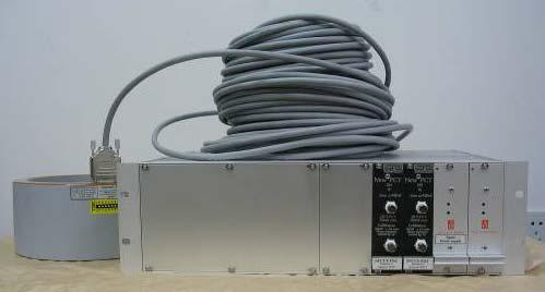
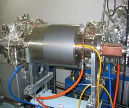
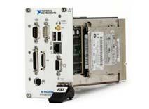
23 Average current measurement: DCCT Shield design borrowed from SPEAR3 Bergoz NPCT175 NI 4070 DVM NI 8187 PXI controller
24 DCCT readings / I DCCT (ma) Current readings deviation (μa) DCCT performance evaluation SSRF Ring DCCT linearity Measured data Linear fitting I DCCT = I INPUT * A + B A = ± B = ± Calibration current setting / I INPUT (ma) 1 SSRF DCCT resolution real beam current calibrator Input current (ma) Ring Resolution < 1Hz Nonlinearity < 0 ~ 300mA DCCT readings / I DCCT (ma) Current readings deviation (μa) SSRF Booster DCCT linearity Measured data Linear fitting I DCCT = I INPUT * A + B A = ± B = ± Calibration current setting / I INPUT (ma) SSRF Booster DCCT resolution Current calibrator Input current (ma) Booster Resolution < 10kHz, < 2Hz Nonlinearity < 0 ~ 20mA
 -40-60 -80-100 -120-140")

 1000 samples RMS: 0.009/1.067nC = 0.8% P-P: 0.06/1.")
25 Bunch charge measurement: ICT Scope embedded IOC TEK DPO7054 BW 500MHz 20 ICT raw waveform acquired by scope IOC 0-20 Amplitude (mv) Bergoz ICT Time (ns) Counts ICT resolution Total samples1000 Average = 1.067nC STD = 9pC / = 0.8% ICT readings (nc) 1000 samples RMS: 0.009/1.067nC = 0.8% P-P: 0.06/1.067 = 5%
 0.8 0.6 0.4 0.")
26 Bunch charge measurement: BPM Storage ring filling Bunch charge (nc) Acquiris DC252, BW 2GHz Sampling rate 8GHz PXI BCM BCM full range = 1nC, readings STD = 0.9pC Bunch ID PXI BCM readings, average = 0.23nC, STD = 0.9pC Bunch ID = 96 Bunch charge (nc) Bunch ID 304 ~ 306, lifetime ~ 14 hours Bunch ID 311 ~ 314, lifetime ~ 18 hours Bunch ID 308 ~ 310, lifetime ~ 21 hours Counts Time (hours) 2000 samples RMS: 0.9pC/1.0nC = 0.1% Bunch charge readings varation (pc)
27 Diagnostics Beam Line Design goals Achievement Beam size 10um 10um Beam length 2ps 2ps

28 Layout #2 BM I the cell #2
29 Diagnostics beam line: bench setup Removable mirror V interferometer From source point 1677cm CCD CCD Horizontal 217 Vertical Gated Camera H interferometer Imaging Streak camera Gated camera 55 Streak Camera Removable mirror 15 CCD Mirror Half mirror Lense Double slit
30 Diagnostics beam line: image system mA, no COD correction copper cavity mA, COD um level copper cavity mA SC cavity, noisy PS mA SC cavity, noisy PS fixed


31 Diagnostics beam line: Interferometer Counts Vertical beamsize = , 202.2mA Beam size readings varation (μm) Counts Horizontal beamsize = , 190.7mA Beam size readings varation (μm) Measured beam size (μm) Horizontal beam size Vertical beam size Beam current (ma) Measurement uncertainty um level, system resolution better than 10um
32 Transverse Feedback Bandwidth System gain Design goals 250Mhz Achievement 250Mhz > 40dB


33 Transverse feedback Stripline injection section, BPM #2 straight section Spring8 designed digital feedback processor In-house made separate stripline kicker in-house made RF front-end Betatron oscillation attenuation > 40dB
 90 70 50 30 Feedback ON, δ V = 32±4μm Feedback OFF, δ V = 101±2μm Feedback ON 0 5 10 15 20 Time (minutes) 10 2 Beam")
 10 0 10-2 10-4 299.6kHz / 0.4317 Amplitude = 2.2E-4 PSD (um 2 /Hz) 10 0 10-2 10-4 195.5kHz / 0.2817 Amplitude = 5.")
34 Transverse feedback performance SSRF multibunch transverse feedback system GeV, SC RF Current = 140mA Vertical beamsize (μm) Feedback ON, δ V = 32±4μm Feedback OFF, δ V = 101±2μm Feedback ON Time (minutes) 10 2 Beam power 3.5GeV, 140mA, MBTF OFF 197.2kHz / Amplitude = 29 X plane Y plane 10 2 Beam power 3.5GeV, 140mA, MBTF ON X plane Y plane PSD (um 2 /Hz) kHz / Amplitude = 2.2E-4 PSD (um 2 /Hz) kHz / Amplitude = 5.8E-4 System gain 29/7E-4 > 40dB Frequency(kHz) Frequency(kHz)
35 Status of the other components Screen monitor is daily operation toolkits for Linac & TL important in day one commissioning for both booster & ring Slit is rarely used now used few times during booster commissioning Scraper is very useful for machine study used as collimator to protect IDs in daily operation WCM is rarely used now good tools for operator in commissioning stage Fast orbit feedback is under commissioning
36 LINAC LTB BTS BS SR Summary (1) Measurement Specification Achievement Beam position Resolution < SP Beam profile Resolution 200μm@2Hz 2Hz Bunch charge Relative accuracy 2% 1% Energy Relative accuracy 0.1% 0.1% Emmitance Relative accuracy 10% 10% Beam position Resolution 100μm@1.67MHz < 50um@1.67MHz Beam profile Resolution 200μm@2Hz 2Hz DC current Resolution 50μA@10kHz 30uA@10kHz 10uA@2Hz Tune Resolution 0.001@200Hz 0.001@800Hz Beam position Resolution 10μm@694kHz 694kHz Resolution 1μm@10Hz 10Hz Beam profile Resolution 10μm 10um Beam length Resolution 2ps 2ps DC current Resolution 10μA@1Hz 1Hz Tune Resolution @1Hz @1Hz MBTF BW 250MHz BW 250MHz, -40dB gain
37 Summary (2) Beam diagnostics meets all physical requirements All necessary diagnostics tools ready in day one for commissioning Adopting new technologies and methods accelerates system development and implementation All design goals achieved except fast orbit feedback Fast orbit feedback could be online this year We need keep working on stability & reliability issues
38 Acknowledgments The development of SSRF beam diagnostics is a successful story of international collaboration. Without comments, suggestions from accelerator community we could not make it. In particularly many thanks to Guenther Rehm and Michael Abbott from Diamond Light Source Bob Hettel, Jim Sebek, James Safranek, Jeff Corbett from SLAC Tadayoshi Misuhashi from KEK Takeshi Nakamura from Sring8 Jean-Claude Denard from Soleil Light Source Hsu Kuo-Tung from Taiwai Light Source Cao Jian-She She and Ma Li from IHEP Sun Bao-Geng Geng from NSRL We hope we can do more contribution to this community in the future.
39
Brilliance. Electron Beam Position Processor
 Brilliance Electron Beam Position Processor Many instruments. Many people. Working together. Stability means knowing your machine has innovative solutions. For users, stability means a machine achieving
Accelerator Systems of the TPS
 Ambient Ground Motion and Civil Engineering for Low Emittance Electron Storage Ring July 2-22, 2005, Hsinchu, Taiwan Accelerator Systems of the TPS Preinjector, Booster Synchrotron, Transfer Line, and
Digital BPMs and Orbit Feedback Systems
 Digital BPMs and Orbit Feedback Systems, M. Böge, M. Dehler, B. Keil, P. Pollet, V. Schlott Outline stability requirements at SLS storage ring digital beam position monitors (DBPM) SLS global fast orbit
SPEAR 3: Operations Update and Impact of Top-Off Injection
 SPEAR 3: Operations Update and Impact of Top-Off Injection R. Hettel for the SSRL ASD 2005 SSRL Users Meeting October 18, 2005 SPEAR 3 Operations Update and Development Plans Highlights of 2005 SPEAR 3
Fast Orbit Feedback at the SLS. Outline
 Fast Orbit Feedback at the SLS 2nd Workshop on Beam Orbit Stabilisation (December4-6, 2002, SPring-8) T. Schilcher Outline Noise Sources at SLS Stability / System Requirements Fast Orbit Feedback Implementation
LHC Beam Instrumentation Further Discussion
 LHC Beam Instrumentation Further Discussion LHC Machine Advisory Committee 9 th December 2005 Rhodri Jones (CERN AB/BDI) Possible Discussion Topics Open Questions Tune measurement base band tune & 50Hz
The basic parameters of the pre-injector are listed in the Table below. 100 MeV
 3.3 The Pre-injector The high design brightness of the SLS requires very high phase space density of the stored electrons, leading to a comparatively short lifetime of the beam in the storage ring. This,
First Simultaneous Top-up Operation of Three Different Rings in KEK Injector Linac
 First Simultaneous Top-up Operation of Three Different Rings in KEK Injector Linac Masanori Satoh (Acc. Lab., KEK) for the injector upgrade group 2010/9/16 1 Overview of Linac Beam Operation 2010/9/16
NSLS2 Diagnostic System Commissioning and Measurements
 NSLS2 Diagnostic System Commissioning and Measurements Weixing Cheng, on behalf of NSLS2 diagnostic group and commissioning team 3 rd International Beam Instrumentation Conference Monterey, California,
An Overview of Beam Diagnostic and Control Systems for AREAL Linac
 An Overview of Beam Diagnostic and Control Systems for AREAL Linac Presenter G. Amatuni Ultrafast Beams and Applications 04-07 July 2017, CANDLE, Armenia Contents: 1. Current status of existing diagnostic
ALBA. Libera Workshop 16 A. Olmos
 LIBERAs @ ALBA Libera Workshop 16 A. Olmos Content Fast Orbit Feedback At a glance Equipments Implementation Limitations In operation Bunch-by- Bunch system At a glance Ported Software Status What else
The Elettra Storage Ring and Top-Up Operation
 The Elettra Storage Ring and Top-Up Operation Emanuel Karantzoulis Past and Present Configurations 1994-2007 From 2008 5000 hours /year to the users 2010: Operations transition year Decay mode, 2 GeV (340mA)
Bunch-by-bunch feedback and LLRF at ELSA
 Bunch-by-bunch feedback and LLRF at ELSA Dmitry Teytelman Dimtel, Inc., San Jose, CA, USA February 9, 2010 Outline 1 Feedback Feedback basics Coupled-bunch instabilities and feedback Beam and feedback
Non-Invasive Energy Spread Monitoring for the JLAB Experimental Program via Synchrotron Light Interferometers
 Non-Invasive for the JLAB Experimental Program via Synchrotron Light Interferometers P. Chevtsov, T. Day, A.P. Freyberger, R. Hicks Jefferson Lab J.-C. Denard Synchrotron SOLEIL 20th March 2005 1. Energy
Beam Position Monitor Developments at PSI
 Paul Scherrer Institut V. Schlott for the PSI Diagnostics Section Wir schaffen Wissen heute für morgen Beam Position Monitor Developments at PSI Overview Motivation European XFEL BPM Systems SwissFEL BPM
PEP-II longitudinal feedback and the low groupdelay. Dmitry Teytelman
 PEP-II longitudinal feedback and the low groupdelay woofer Dmitry Teytelman 1 Outline I. PEP-II longitudinal feedback and the woofer channel II. Low group-delay woofer topology III. Why do we need a separate
The Backlog The Scope The Approach The Trends
 BPM Development at Instrumentation Technologies Rok Hrovatin, Borut Baričevič, Tomaž Beltram, Matej Kenda 8th DITANET workshop on BPMs, Januar 202 rok.hrovatin@i-tech.si The Backlog The Scope The Approach
Precision measurements of beam current, position and phase for an e+e- linear collider
 Precision measurements of beam current, position and phase for an e+e- linear collider R. Corsini on behalf of H. Braun, M. Gasior, S. Livesley, P. Odier, J. Sladen, L. Soby INTRODUCTION Commissioning
COMMISSIONING OF THE ALBA FAST ORBIT FEEDBACK SYSTEM
 COMMISSIONING OF THE ALBA FAST ORBIT FEEDBACK SYSTEM A. Olmos, J. Moldes, R. Petrocelli, Z. Martí, D. Yepez, S. Blanch, X. Serra, G. Cuni, S. Rubio, ALBA-CELLS, Barcelona, Spain Abstract The ALBA Fast
North Damping Ring RF
 North Damping Ring RF North Damping Ring RF Outline Overview High Power RF HVPS Klystron & Klystron EPICS controls Cavities & Cavity Feedback SCP diagnostics & displays FACET-specific LLRF LLRF distribution
NSLS-II RF BEAM POSITION MONITOR COMMISSIONING UPDATE
 NSLS-II RF BEAM POSITION MONITOR COMMISSIONING UPDATE Joseph Mead#, Anthony Caracappa, Weixing Cheng, Christopher Danneil, Joseph DeLong, Al DellaPenna, Kiman Ha, Bernard Kosciuk, Marshall Maggipinto,
Sérgio Rodrigo Marques
 Sérgio Rodrigo Marques (on behalf of the beam diagnostics group) sergio@lnls.br Outline Introduction Stability Requirements General System Requirements FOFB Strategy Hardware Overview Performance Tests:
1 Digital BPM Systems for Hadron Accelerators
 Digital BPM Systems for Hadron Accelerators Proton Synchrotron 26 GeV 200 m diameter 40 ES BPMs Built in 1959 Booster TT70 East hall CB Trajectory measurement: System architecture Inputs Principles of
Libera Hadron: demonstration at SPS (CERN)
") Creation date: 07.10.2011 Last modification: 14.10.2010 Libera Hadron: demonstration at SPS (CERN) Borut Baričevič, Matjaž Žnidarčič Introduction Libera Hadron has been demonstrated at CERN. The demonstration
Creation date: 07.10.2011 Last modification: 14.10.2010 Libera Hadron: demonstration at SPS (CERN) Borut Baričevič, Matjaž Žnidarčič Introduction Libera Hadron has been demonstrated at CERN. The demonstration
Recent APS Storage Ring Instrumentation Developments. Glenn Decker Advanced Photon Source Beam Diagnostics March 1, 2010
 Recent APS Storage Ring Instrumentation Developments Glenn Decker Advanced Photon Source Beam Diagnostics March 1, 2010 Ring Diagnostics Overview RF beam position monitor technology Photon beam position
Features of the 745T-20C: Applications of the 745T-20C: Model 745T-20C 20 Channel Digital Delay Generator
 20 Channel Digital Delay Generator Features of the 745T-20C: 20 Independent delay channels - 100 ps resolution - 25 ps rms jitter - 10 second range Output pulse up to 6 V/50 Ω Independent trigger for every
PEP II Design Outline
 PEP II Design Outline Balša Terzić Jefferson Lab Collider Review Retreat, February 24, 2010 Outline General Information Parameter list (and evolution), initial design, upgrades Collider Ring Layout, insertions,
ANKA Status Report. N.Smale, A.-S. Müller, E. Huttel, M.Schuh Slides courtesy of A.-S. Müller and C.Heske.
 ANKA Status Report N.Smale, A.-S. Müller, E. Huttel, M.Schuh Slides courtesy of A.-S. Müller and C.Heske. KIT - University of the State of Baden-Wuerttemberg and National Laboratory of the Helmholtz Association
New Filling Pattern for SLS-FEMTO
 SLS-TME-TA-2009-0317 July 14, 2009 New Filling Pattern for SLS-FEMTO Natalia Prado de Abreu, Paul Beaud, Gerhard Ingold and Andreas Streun Paul Scherrer Institut, CH-5232 Villigen PSI, Switzerland A new
Top-Up Experience at SPEAR3
 Top-Up Experience at SPEAR3 Contents SPEAR 3 and the injector Top-up requirements Hardware systems and modifications Safety systems & injected beam tracking Interlocks & Diagnostics SPEAR3 Accelerator
LCLS RF Reference and Control R. Akre Last Update Sector 0 RF and Timing Systems
 LCLS RF Reference and Control R. Akre Last Update 5-19-04 Sector 0 RF and Timing Systems The reference system for the RF and timing starts at the 476MHz Master Oscillator, figure 1. Figure 1. Front end
LLRF at SSRF. Yubin Zhao
 LLRF at SSRF Yubin Zhao 2017.10.16 contents SSRF RF operation status Proton therapy LLRF Third harmonic cavity LLRF Three LINAC LLRF Hard X FEL LLRF (future project ) Trip statistics of RF system Trip
Development of BPM Electronics at the JLAB FEL
 Development of BPM Electronics at the JLAB FEL D. Sexton, P. Evtushenko, K. Jordan, J. Yan, S. Dutton, W. Moore, R. Evans, J. Coleman Thomas Jefferson National Accelerator Facility, Free Electron Laser
Session 07 - What did we learn with beam in 2008? LHC Performance Workshop Chamonix Rhodri Jones on behalf of BE/BI & all our collaborators
 - First Results & Next Steps Session 07 - What did we learn with beam in 2008? LHC Performance Workshop Chamonix 2009 Rhodri Jones on behalf of BE/BI & all our collaborators LHC BTV System All screens
Diamond RF Status (RF Activities at Daresbury) Mike Dykes
 Mike Dykes") Diamond RF Status (RF Activities at Daresbury) Mike Dykes ASTeC What is it? What does it do? Diamond Status Linac Booster RF Storage Ring RF Summary Content ASTeC ASTeC was formed in 2001 as a centre of
Diamond RF Status (RF Activities at Daresbury) Mike Dykes ASTeC What is it? What does it do? Diamond Status Linac Booster RF Storage Ring RF Summary Content ASTeC ASTeC was formed in 2001 as a centre of
PRELIMINARY INFORMATION. Professional Signal Generation and Monitoring Options for RIFEforLIFE Research Equipment
 Integrated Component Options Professional Signal Generation and Monitoring Options for RIFEforLIFE Research Equipment PRELIMINARY INFORMATION SquareGENpro is the latest and most versatile of the frequency
RF considerations for SwissFEL
 RF considerations for H. Fitze in behalf of the PSI RF group Workshop on Compact X-Ray Free Electron Lasers 19.-21. July 2010, Shanghai Agenda Introduction RF-Gun Development C-band development Summary
LIGHT PROTON THERAPY PROJECT
 17 th of MAY 2018 LIGHT PROTON THERAPY PROJECT Yevgeniy Ivanisenko on behalf of ADAM team FORM-01040-A AVO-ADAM Advanced Oncotherapy (AVO) is a public company ADAM is R&D center of AVO ~ 100 employees
MSO-28 Oscilloscope, Logic Analyzer, Spectrum Analyzer
 Link Instruments Innovative Test & Measurement solutions since 1986 Store Support Oscilloscopes Logic Analyzers Pattern Generators Accessories MSO-28 Oscilloscope, Logic Analyzer, Spectrum Analyzer $ The
BEPCII Libera Control System
 BEPCII Libera Control System Beam Instrument Group Accelerator Research Center IHEP Huizhou Ma 2010.3 BEPCII Libera Control System Outline Introduction of Libera Libera PVs Libera System Overview Soft
Diagnostics Development in SRRC
 Diagnostics Development in SRRC K. T. Hsu, C. H. Kuo, Jenny Chen, C. S. Chen, K. K. Lin, C. C. Kuo, Richard Sah _ Synchrotron Radiation Research Center, No. 1 R&D Road VI, Hsinchu Science-Based Industrial
Characterizing Transverse Beam Dynamics at the APS Storage Ring Using a Dual-Sweep Streak Camera
 Characterizing Transverse Beam Dynamics at the APS Storage Ring Using a Dual-Sweep Streak Camera Bingxin Yang, Alex H. Lumpkin, Katherine Harkay, Louis Emery, Michael Borland, and Frank Lenkszus Advanced
Linac 4 Instrumentation K.Hanke CERN
 Linac 4 Instrumentation K.Hanke CERN CERN Linac 4 PS2 (2016?) SPL (2015?) Linac4 (2012) Linac4 will first inject into the PSB and then can be the first element of a new LHC injector chain. It will increase
CBF500 High resolution Streak camera
 High resolution Streak camera Features 400 900 nm spectral sensitivity 5 ps impulse response 10 ps trigger jitter Trigger external or command 5 to 50 ns analysis duration 1024 x 1024, 12-bit readout camera
ANKA RF System - Upgrade Strategies
 ANKA RF System - Upgrade Strategies Vitali Judin ANKA Synchrotron Radiation Facility 2014-09 - 17 KIT University of the State Baden-Wuerttemberg and National Laboratory of the Helmholtz Association www.kit.edu
Low Level RF for PIP-II. Jonathan Edelen LLRF 2017 Workshop (Barcelona) 16 Oct 2017
 16 Oct 2017") Low Level RF for PIP-II Jonathan Edelen LLRF 2017 Workshop (Barcelona) 16 Oct 2017 PIP-II LLRF Team Fermilab Brian Chase, Edward Cullerton, Joshua Einstein, Jeremiah Holzbauer, Dan Klepec, Yuriy Pischalnikov,
Low Level RF for PIP-II Jonathan Edelen LLRF 2017 Workshop (Barcelona) 16 Oct 2017 PIP-II LLRF Team Fermilab Brian Chase, Edward Cullerton, Joshua Einstein, Jeremiah Holzbauer, Dan Klepec, Yuriy Pischalnikov,
Status of SOLARIS Arkadiusz Kisiel
 Status of SOLARIS Arkadiusz Kisiel Solaris National Synchrotron Light Source Jagiellonian University Czerwone Maki 98 30-392 Kraków www.synchrotron.uj.edu.pl Arkadiusz.Kisiel@uj.edu.pl On behalf of SOLARIS
INTRODUCTION. SLAC-PUB-8414 March 2000
 SLAC-PUB-8414 March 2 Beam Diagnostics Based on Time-Domain Bunch-by-Bunch Data * D. Teytelman, J. Fox, H. Hindi, C. Limborg, I. Linscott, S. Prabhakar, J. Sebek, A. Young Stanford Linear Accelerator Center
GFT Channel Digital Delay Generator
 Features 20 independent delay Channels 100 ps resolution 25 ps rms jitter 10 second range Output pulse up to 6 V/50 Ω Independent trigger for every channel Fours Triggers Three are repetitive from three
BUNCH BY BUNCH FEEDBACK SYSTEMS FOR SUPERKEKB RINGS
 August 8-1, 216, Chiba, Japan PASJ216 TUOM6 BUNCH BY BUNCH FEEDBACK SYSTEMS FOR SUPERKEKB RINGS Makoto Tobiyama, John W. Flanagan, KEK Accelerator Laboratory, 1-1 Oho, Tsukuba 35-81, Japan, and Graduate
ANKA Status Report. N.Smale, on behalf of all ANKA colleagues, Directors : A.-S. Müller, C Heske, T Baumbach.
 ANKA Status Report N.Smale, on behalf of all ANKA colleagues, Directors : A.-S. Müller, C Heske, T Baumbach. Institute for Synchrotron Radiation KIT - University of the State of Baden-Wuerttemberg and
Production of quasi-monochromatic MeV photon in a synchrotron radiation facility
 Production of quasi-monochromatic MeV photon in a synchrotron radiation facility Presentation at University of Saskatchewan April 22-23, 2010 Yoshitaka Kawashima Brookhaven National Laboratory NSLS-II,
Detailed Design Report
 Detailed Design Report Chapter 4 MAX IV Injector 4.6. Acceleration MAX IV Facility CHAPTER 4.6. ACCELERATION 1(10) 4.6. Acceleration 4.6. Acceleration...2 4.6.1. RF Units... 2 4.6.2. Accelerator Units...
JLab 10kW FEL Driver Beam Diagnostics
 JLab 10kW Driver Beam Diagnostics Kevin Jordan, S. V. Benson, J. Coleman, D. Douglas, R. Evans, A. Grippo, D. Gruber, G. Krafft, W. Moore, N. Nishimori, P. Piot, D. Sexton, J. Song and S. Zhang Outline.
Jefferson Lab Experience with Beam Halo, Beam Loss, etc.
 Jefferson Lab Experience with Beam Halo, Beam Loss, etc. Pavel Evtushenko with a lot of input from many experienced colleagues Steve Benson, Dave Douglas, Kevin Jordan, Carlos Hernandez-Garcia, Dan Sexton,
4.4 Injector Linear Accelerator
 4.4 Injector Linear Accelerator 100 MeV S-band linear accelerator based on the components already built for the S-Band Linear Collider Test Facility at DESY [1, 2] will be used as an injector for the CANDLE
Status of the X-ray FEL control system at SPring-8
 Status of the X-ray FEL control system at SPring-8 T.Fukui 1, T.Hirono 2, N.Hosoda 1, M.Ishii 2, M.Kitamura 1 H.Maesaka 1,T.Masuda 2, T.Matsushita 2, T.Ohata 2, Y.Otake 1, K.Shirasawa 1,M.Takeuchi 2, R.Tanaka
Status of SOLARIS. Paweł Borowiec On behalf of Solaris Team
 Status of SOLARIS Paweł Borowiec On behalf of Solaris Team e-mail: pawel.borowiec@uj.edu.pl XX ESLS-RF Meeting, Villingen 16-17.11.2016 Outline 1. Timeline 2. Injector 3. Storage ring 16-17.11.2016 XX
Status of Elettra, top-up and other upgrades
 Status of Elettra, top-up and other upgrades Emanuel Karantzoulis ELETTRA / Trieste, Italy / 2010 November 25-26 Past and Present Configurations 1994-2007 From 2008 No full energy injection Full energy
COMMISSIONING SCENARIOS FOR THE J-PARC ACCELERATOR COMPLEX
 COMMISSIONING SCENARIOS FOR THE J-PARC ACCELERATOR COMPLEX T. Koseki, M. Ikegami, M. Tomizawa, Accelerator Laboratory, KEK, Tsukuba, Japan F. Noda, JAEA, Tokai, Japan Abstract The J-PARC (Japan Proton
Beam Instrumentation for X-ray FELs
 Beam Instrumentation for X-ray FELs 05/16/2011 1 1 Outline X-ray FEL overview Diagnostics requirements for X-ray FELs Transverse Diagnostics Longitudinal Diagnostics Summary 2 2 X-ray FEL Overview 100
THE DESIGN OF CSNS INSTRUMENT CONTROL
 THE DESIGN OF CSNS INSTRUMENT CONTROL Jian Zhuang,1,2,3 2,3 2,3 2,3 2,3 2,3, Jiajie Li, Lei HU, Yongxiang Qiu, Lijiang Liao, Ke Zhou 1State Key Laboratory of Particle Detection and Electronics, Beijing,
THE SLS BEAMLINES DATA ACQUISITION AND CONTROL SYSTEM
 PSN THE SLS BEAMLINES DATA ACQUISITION AND CONTROL SYSTEM Abstract J.Krempasky, R.Krempaska, D.Vermeulen, D.Maden, T.Korhonnen, W.Portmann, S.Hunt, R.Abela, PSI-SLS, Villigen, Switzerland, M.Muntwiler,
LCLS Injector Technical Review
 LCLS Injector Technical Review Stanford Linear Accelerator Center November 3&4 2003 Review Committee Members: Prof. Patrick O Shea Chair University of Maryland Dr. E. Colby Stanford Linear Accelerator
beam dump from P2 losses this morning
 beam dump from P2 losses this morning Some observations on the beam dump from P2 losses this morning 29.10.10 at 01:26:39: - single bunch intensity (average) was ~1.3e11 - significantly higher than previous
Position Resolution of Optical Fibre-Based Beam Loss Monitors using long electron pulses
 Position Resolution of Optical Fibre-Based Beam Loss Monitors using long electron pulses E. Nebot del Busto (1,2, 3), M. J. Boland (4,5), S. Doebert (1), F. S. Domingues (1), E. Effinger (1), W. Farabolini
Operational experience with the SOLEIL LINAC and Status of the ThomX LINAC project
 Operational experience with the SOLEIL LINAC and Status of the ThomX LINAC project 16/11/2016 20th ELS-RF Workshop Pollina JP 1 and Status of the ThomX LINAC project Operational experience with the SOLEIL
The 2011 LHC Run - Lessons in Beam Diagnostics
 The 2011 LHC Run - Lessons in Beam Diagnostics LHC Performance Workshop Chamonix 2012 6 th 10 th February Rhodri Jones on behalf of the CERN Beam Instrumentation Group Outline This Presentation will focus
Jae-Young Choi On behalf of PLS-II Linac team
 PLS-II Linac 2015. 4. 8. Jae-Young Choi On behalf of PLS-II Linac team Accelerators in Pohang Accelerator Laboratory XFEL (under construction) 400 M$ Machines under installation PLS-II PAL : Chronology
FIRST SIMULTANEOUS TOP-UP OPERATION OF THREE DIFFERENT RINGS IN KEK INJECTOR LINAC
 FIRST SIMULTANEOUS TOP-UP OPERATION OF THREE DIFFERENT RINGS IN KEK INJECTOR LINAC M. Satoh #, for the IUC * Accelerator Laboratory, High Energy Accelerator Research Organization (KEK) 1-1 Oho, Tsukuba,
G0 Laser Status Parity Controls Injector Diagnostics
 G0 Laser Status Parity Controls Injector Diagnostics G0 Collaboration Mtg Jefferson Lab August 16, 2002 G0 Collaboration Mtg (August 16, 2002), 1 Installed new AOM homebuilt laser G0 Collaboration Mtg
Summary report on synchronization, diagnostics and instrumentation
 Summary report on synchronization, diagnostics and instrumentation A.P. Freyberger and G.A. Krafft Jefferson Lab, 12000 Jefferson Avenue, Newport News, VA. 23606 Abstract The proceedings of Working Group
Accelerator Instrumentation RD. Monday, July 14, 2003 Marc Ross
 Monday, Marc Ross Linear Collider RD Most RD funds address the most serious cost driver energy The most serious impact of the late technology choice is the failure to adequately address luminosity RD issues
Beam Loss Detection for MPS at FRIB
 Beam Loss Detection for MPS at FRIB Zhengzheng Liu Beam Diagnostics Physicist This material is based upon work supported by the U.S. Department of Energy Office of Science under Cooperative Agreement DE-SC0000661.
Operation and Performance of a Longitudinal Feedback System Using Digital Signal Processing*
 SLAC-PUB-6675 LBL-36174 November 22, 1994 Operation and Performance of a Longitudinal Feedback System Using Digital Signal Processing* D. Teytelman, J. Fox, H. Hindi, J. Hoeflich, I. Linscott, J. Olsen,
P. Emma, et al. LCLS Operations Lectures
 P. Emma, et al. LCLS Operations Lectures LCLS 1 LCLS Accelerator Schematic 6 MeV 135 MeV 250 MeV σ z 0.83 mm σ z 0.83 mm σ z 0.19 mm σ δ 0.05 % σ δ 0.10 % σ δ 1.6 % Linac-0 L =6 m rf gun L0-a,b Linac-1
Phase (deg) Phase (deg) Positive feedback, 317 ma. Negative feedback, 330 ma. jan2898/1638: beam pseudospectrum around 770*frev.
 Phase (deg) Positive feedback, 317 ma. Negative feedback, 330 ma. jan2898/1638: beam pseudospectrum around 770*frev.") Commissioning Experience from PEP-II HER Longitudinal Feedback 1 S. Prabhakar, D. Teytelman, J. Fox, A. Young, P. Corredoura, and R. Tighe Stanford Linear Accelerator Center, Stanford University, Stanford,
Commissioning Experience from PEP-II HER Longitudinal Feedback 1 S. Prabhakar, D. Teytelman, J. Fox, A. Young, P. Corredoura, and R. Tighe Stanford Linear Accelerator Center, Stanford University, Stanford,
PEP-II Overview & Ramp Down Plan. J. Seeman DOE PEP-II Ramp Down-D&D Review August 6-7, 2007
 PEP-II Overview & Ramp Down Plan J. Seeman DOE PEP-II Ramp Down-D&D Review August 6-7, 2007 Topics Overview of the PEP-II Collider PEP-II turns off September 30, 2008. General list of components and buildings
Screen investigations for low energetic electron beams at PITZ
 1 Screen investigations for low energetic electron beams at PITZ S. Rimjaem, J. Bähr, H.J. Grabosch, M. Groß Contents Review of PITZ setup Screens and beam profile monitors at PITZ Test results Summary
KARA and FLUTE RF Overview/status
 KARA and FLUTE RF Overview/status Nigel Smale on behalf of IBPT and LAS teams Laboratory for Applications of Synchrotron radiation (LAS) Institute for Beam Physics and Technology (IBPT) KARA KIT The Research
Zynq platform and related instruments
 Libera Single Pass E / Matjaž Žnidarčič, 12.10.2012 Zynq platform and related instruments Peter Leban, DEELS, June 2017, Paris Content Peter's project Company's projects (continuation) (continuation) LAST
Beam Diagnostics for the BNL Energy Recovery Linac Test Facility
 Beam Diagnostics for the BNL Energy Recovery Linac Test Facility Peter Cameron, Ilan Ben-Zvi, Michael Blaskiewicz, Michael Brennan, Roger Connolly, William Dawson, Chris Degen, Al DellaPenna, David Gassner,
Feedback Control of SPS E-Cloud/TMCI Instabilities
 Feedback Control of SPS E-Cloud/TMCI Instabilities C. H. Rivetta 1 LARP Ecloud Contributors: A. Bullitt 1, J. D. Fox 1, T. Mastorides 1, G. Ndabashimiye 1, M. Pivi 1, O. Turgut 1, W. Hofle 2, B. Savant
TWO BUNCHES WITH NS-SEPARATION WITH LCLS*
 TWO BUNCHES WITH NS-SEPARATION WITH LCLS* F.-J. Decker, S. Gilevich, Z. Huang, H. Loos, A. Marinelli, C.A. Stan, J.L. Turner, Z. van Hoover, S. Vetter, SLAC, Menlo Park, CA 94025, USA Abstract The Linac
IOT OPERATIONAL EXPERIENCE ON ALICE AND EMMA AT DARESBURY LABORATORY
 IOT OPERATIONAL EXPERIENCE ON ALICE AND EMMA AT DARESBURY LABORATORY A. Wheelhouse ASTeC, STFC Daresbury Laboratory ESLS XVIII Workshop, ELLETRA 25 th 26 th November 2010 Contents Brief Description ALICE
CLIC Feasibility Demonstration at CTF3
 CLIC Feasibility Demonstration at CTF3 Roger Ruber Uppsala University, Sweden, for the CLIC/CTF3 Collaboration http://cern.ch/clic-study LINAC 10 MO303 13 Sep 2010 The Key to CLIC Efficiency NC Linac for
2008 JINST 3 S LHC Machine THE CERN LARGE HADRON COLLIDER: ACCELERATOR AND EXPERIMENTS. Lyndon Evans 1 and Philip Bryant (editors) 2
 2") PUBLISHED BY INSTITUTE OF PHYSICS PUBLISHING AND SISSA RECEIVED: January 14, 2007 REVISED: June 3, 2008 ACCEPTED: June 23, 2008 PUBLISHED: August 14, 2008 THE CERN LARGE HADRON COLLIDER: ACCELERATOR AND
PUBLISHED BY INSTITUTE OF PHYSICS PUBLISHING AND SISSA RECEIVED: January 14, 2007 REVISED: June 3, 2008 ACCEPTED: June 23, 2008 PUBLISHED: August 14, 2008 THE CERN LARGE HADRON COLLIDER: ACCELERATOR AND
PITZ Introduction to the Video System
 PITZ Introduction to the Video System Stefan Weiße DESY Zeuthen June 10, 2003 Agenda 1. Introduction to PITZ 2. Why a video system? 3. Schematic structure 4. Client/Server architecture 5. Hardware 6. Software
Photoinjector Laser Operation and Cathode Performance
 Photoinjector Laser Operation and Cathode Performance Daniele Sertore, INFN Milano LASA Siegfried Schreiber, DESY Laser operational experience Laser beam properties Cathode performances Outlook TTF and
Polarized Source Development Run Results
 Polarized Source Development Run Results Riad Suleiman Injector Group November 18, 2008 Outline Injector Parity DAQ and Helicity Board Pockels Cell Alignment Fast Helicity Reversal Studies: o 30 Hz, 250
The FLASH objective: SASE between 60 and 13 nm
 Injector beam control studies winter 2006/07 talk from E. Vogel on work performed by W. Cichalewski, C. Gerth, W. Jalmuzna,W. Koprek, F. Löhl, D. Noelle, P. Pucyk, H. Schlarb, T. Traber, E. Vogel, FLASH
BUNCH-BY-BUNCH DIAGNOSTICS AT THE APS USING TIME- CORRELATED SINGLE-PHOTON COUNTING TECHNIQUES*
 BUNCH-BY-BUNCH DIAGNOSTICS AT THE APS USING TIME- CORRELATED SINGLE-PHOTON COUNTING TECHNIQUES* B. X. Yang, W. E. Norum, S. Shoaf, and J. Stevens Advanced Photon Source, Argonne National Laboratory, Argonne,
MULTI-BUNCH INSTABILITY DIAGNOSTICS VIA DIGITAL FEEDBACK SYSTEMS AT PEP-II, DAæNE, ALS and SPEAR
 MULTI-BUNCH INSTABILITY DIAGNOSTICS VIA DIGITAL FEEDBACK SYSTEMS AT PEP-II, DAæNE, ALS and SPEAR J. Fox æ R. Larsen, S. Prabhakar, D. Teytelman, A. Young, SLAC y A. Drago, M. Serio, INFN Frascati; W. Barry,
CONSTRUCTION AND COMMISSIONING OF BEPCII
 Abstract CONSTRUCTION AND COMMISSIONING OF BEPCII C. Zhang, J.Q. Wang, L. Ma and G.X.Pei for the BEPCII Team, IHEP, CAS P.O.Box 918, Beijing 100049, China BEPCII is the major upgrade of BEPC (Beijing Electron-
Choosing an Oscilloscope
 Choosing an Oscilloscope By Alan Lowne CEO Saelig Company (www.saelig.com) Post comments on this article at www.nutsvolts.com/ magazine/article/october2016_choosing-oscilloscopes. All sorts of questions
4 MHz Lock-In Amplifier
 4 MHz Lock-In Amplifier SR865A 4 MHz dual phase lock-in amplifier SR865A 4 MHz Lock-In Amplifier 1 mhz to 4 MHz frequency range Low-noise current and voltage inputs Touchscreen data display - large numeric
Synthesized Clock Generator
 Synthesized Clock Generator CG635 DC to 2.05 GHz low-jitter clock generator Clocks from DC to 2.05 GHz Random jitter
The PEFP 20-MeV Proton Linear Accelerator
 Journal of the Korean Physical Society, Vol. 52, No. 3, March 2008, pp. 721726 Review Articles The PEFP 20-MeV Proton Linear Accelerator Y. S. Cho, H. J. Kwon, J. H. Jang, H. S. Kim, K. T. Seol, D. I.
DESIGN AND DEVELOPMENT OF CONFIGURABLE BPM READOUT SYSTEM FOR ILSF
 DESIN AND DEVELOPMENT OF CONFIURABLE BPM READOUT SYSTEM FOR ILSF M. Shafiee 1,2, J.Rahighi, M.Jafarzadeh, 1 ILSF, Tehran, Iran A.H.Feghhi, 2Shahid beheshti University, Tehran, Iran Abstract A configurable
Control of Intra-Bunch Vertical Motion in the SPS with GHz Bandwidth Feedback
 Journal of Physics: Conference Series PAPER OPEN ACCESS Control of Intra-Bunch Vertical Motion in the SPS with GHz Bandwidth Feedback To cite this article: J. Fox et al 2018 J. Phys.: Conf. Ser. 1067 072024