NSLS2 Diagnostic System Commissioning and Measurements
|
|
|
- Randall Nelson
- 5 years ago
- Views:
Transcription

1 NSLS2 Diagnostic System Commissioning and Measurements Weixing Cheng, on behalf of NSLS2 diagnostic group and commissioning team 3 rd International Beam Instrumentation Conference Monterey, California, USA, Sep , 2014 RHIC NSLS NSLS2
2 Outline NSLS2 introduction and commissioning overview Diagnostic systems commissioning with beam Button BPMs Current monitors (FC, WCM, FCT, ICT, DCCT, FPM) Profile monitors (Screen, SLM) Other diagnostics (Tune, BxB feedback, LCM, etc.) Machine measurements Summary 2
3 NSLS2 Injector BtS SR Injection straight Booster 200-MeV linac 15 nc max, up to 300 ns multibunch train; single bunch mode available, 0.5% energy spread, 50 µm rad 3-GeV booster C=158m, Frf = MHz, h = ma max. current, 1 Hz ramping, 40 nm rad Equipment Racks Injector service area Klystron Gallery LtB Linac Tunnel LINAC 3
 <1nm, 0.")

4 NSLS2 storage ring main parameters Energy 3.0 GeV Circumference 792 m Number of Periods 30 DBA Length Long Straights 6.6 & 9.3m Emittance (h,v) <1nm, 0.008nm Momentum Compaction Dipole Bend Radius 25m Energy Loss per Turn <2MeV Energy Spread 0.094% RF Frequency MHz Harmonic Number 1320 RF Bucket Height >2.5% RMS Bunch Length 15ps-30ps Average Current 500mA Current per Bunch 0.5mA Charge per Bunch 1.3nC Touschek Lifetime >3hrs Top-Off Injection 1/min 4
5 Injector commissioning timeline Mar 26 May , LINAC commissioning. Mis-steering event happened. Nov 27 Dec , LINAC re-start Dec , Start of booster commissioning Dec , Beam through injection septum Dec , First turn in the Booster Dec , Circulating beam Dec , Multibunch mode, better signals, 100 msec circulating beam Dec , RF Capture- synchrotron sidebands observed Dec , Complete injection fault studies, authorization to accelerate Dec , 3 GeV achieved Jan , Start Fault studies with circulating beam Jan , Completed Fault studies with circulating beam Jan , Authorization to extract to the dump Feb , Fault studies in the BtS transport line Feb , Booster commissioning complete successfully 5
6 SR Commissioning timeline Phase 1, Mar 26 May 12, PETRA 7-Cell cavity, DWs installed but not used Mar , authorized to start storage ring commissioning. Mar , first turns in the ring (2-3 turns) Apr , discovered injection pulse kickers had wrong polarity which made injection difficult. Apr , after fixing IS kickers, beam goes around for multi-turns (~10 turns). Observed partial beam lost at C10 BPM4. Apr , beam circulating for ~ 100 turns Apr , stored beam with injection DC bump. Sextupole ON, RF ON Apr , accumulate beam w/o DC bump. Low capture efficiency Apr , scanned dynamic aperture using IS kickers: ~ 4mm, 0.3mrad Apr , achieved 5mA for short period of time Apr , decided to inspect magnets and vacuum aperture near C10 Girder 4, after struggling with beam accumulation. Apr , fixed leakage current issue for all dipoles. Found RF spring hanging in C10, in between first dipole chamber and flange absorber Apr , re-start after fixing the C10 vacuum and dipole leakage current, beam accumulation to 1.5mA then to 5mA (limitation for fault study). Observed longitudinal/vertical beam instability. Apr , 25mA beam stored in multi-trains May , after the phase-i commissioning, found another RF spring in C08 Phase 2, Jun 30 Jul 14, SC cavity, C03, C05 IVUs installed with gap fully open, DWs fully open Jun , tunnel closed, SR cavity conditioning Jul , 25mA with SC RF Jul , 50mA stored beam achieve with SC RF 6


7 50mA stored beam, Jul , SC RF cavity, 1200kV 7


8 RF spring surprises C10 BPM4 First hint of partial beam loss found on Apr , using BPM SUM signal. Beam was circulating for ~10 turns for the first time. Struggled to get accumulated beam. Other evidences shown obstacle in the vacuum near C10. Local bump sweep saw limited aperture; elevated radiation near the area when beam lost; vacuum activities etc. Decided to open the vacuum on Apr-24 and we found the hanging spring at after first dipole in the cell. 8


9 May , after phase-i commissioning. C08 RF Spring, after the first dipole chamber. Flange absorber right upstream of the bellow. The spring was hanging at top-outer corner. It s melted probably due to dipole radiation. y x 9
10 NSLS-II Diagnostics Systems Other Profile Current Position LINAC FE LINAC Booster LTB BTS SR Button BPM ID Button BPM 2 or 3 per ID Photon BPM 1 or 2 per BL Faraday Cup WCM 1 4 FCT/FPM ICT 2 2 DCCT 1 1 Fluorescent / OTR Screen X-Ray Diagnostics beamline 1+1 VSLM Diagnostics beamline 2 1 Energy Slit 1 1 Tune Monitor 1 1 BxB Feedback (H & V) 1+1 Beam Loss Controls - Scrapers 3 H +2 V Beam Loss Monitors (Cerenkov BLMs and Neutron detectors) 5 CBLM 2 NBLM 10
11 1. Position monitors (button BPM) 11


12 BPM timing adjustment, LINAC and LtB BPMs, beam to LtB dump2 LINAC P1 LINAC P2 LINAC P3 LINAC P4 LINAC P5 LtB P1 LtB P2 Dec Multibunch mode, LtB ICT reading nc Beam delivered to LtB dump2 All BPMs set to 0 db RF attenuation BPMs were triggered on the global soft event, so that all BPMs get the same pulse data. LtB P1 is close to saturate, larger button and smaller capacitance Big loss from LtB P1 to P2. Note P2 has power splitter in the signal path. Beam position at P2 is off a lot. 12


13 BPM - Booster first turns Dec , ISVF1 lifted, 2 nd turn signal observed on ISPKU2 and other 3-4 BPMs after injection straight. Turn #2 Dec , ~23:00 multi-turns in booster 13


14 BPM - Booster stored beam, 200MeV, Dec fs fx fy Turn 1:1024 NFFT = 1024 Fsam = Frev df = 1.85 khz 19.41kHz => fs 681kHz => fx khz => fy 14

 ADC raw data, 62")

15 Booster BPMs - Timing adjustment Booster injection at sample #4 Extraction on sample #3966, only first 18 BPMs see the beam signal on that turn. DDR offset turns (380ms) ADC raw data, 62 ADC samples per turn ADC band-pass filtered data. Align the first turn beam signal in ADC sample range


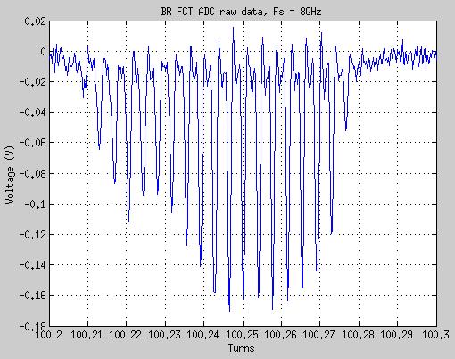
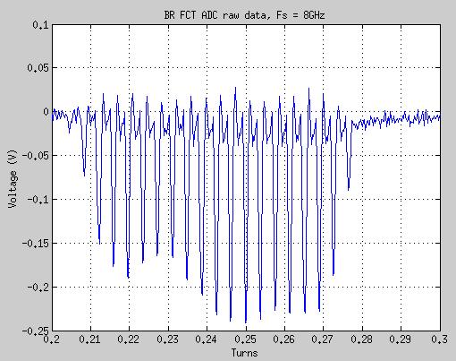
16 Booster BPM applications - Tune Spectrum 1-ν y 1-ν x IS Kic #1 Kicker delay from 10:5:400 ms Kicker amp from 1:0.1:4.9 kv At each delay point, record the BPM TbT data. Fractional tune is above


17 SR BPM first turn ~ 1 turn beam 180 SR BPMs data triggered at: 04/02/2014,08:39:16 Struggling to get beam for multi-turns. Use the measured first turn beam trajectory and fit with machine lattice. Beam at the IS K4 exiting has 21mm horizontal offset, which is far from designed value. Discovered that K3, K4 were kicking the beam in opposite direction. Note: First BPM data (C30 BPM1) is not trustable since beam is too far away from center (~20mm), BPM is in very non-linear range. Y. Li 17


18 SR BPM multi turns Apr , after fixing injection kicker polarities Beam lost partially near C10 BPM4 at every turn around. This is the location where loose RF spring was found later. C10 BPM4 x/y position nonlinearity corrected using 5 th order polynomial Button SUM signal corrected with button geometry, cable attenuations, and beam positions. 18


19 19 J. Mead, WEPD27 SR BPM electronics resolution and timing BPM electronics resolution, C28 SBPM1 combiner/splitter Single bunch May One turn beam Single bunch in bucket #0 No leakage to nearby turns for target bucket #0 - # turns TbT averaged => FA data, resolution ~ 1/sqrt(38)

 v y v x Q T I 0 b β E is the beam energy We get k IbT0 = β k 4πE / e total total IbT0 = 4πE / e is the ring revolution period is the single")
20 SR BPMs TbT beam spectrum Beam was kicked by injection kicker(s) and/or vertical pinger. Record BPM TbT data at different single bunch current. NFFT = 4096, Hanning window Interpolated to get precise tunes v x ~ , don t change much at different current v y ~ 0.205, decreasing at higher current v s ~ 0.007, Vrf = 1.9 MV Noise ~ /mA (-3.07kHz/mA) v y v x Q T I 0 b β E is the beam energy We get k IbT0 = β k 4πE / e total total IbT0 = 4πE / e is the ring revolution period is the single bunch current = 14.8kV / pc / m j β k β is average beta - function, ~ 7.7m for NSLS2 vertical plane j j 20


21 SR BPMs beam spectrum BPM TbT data from 2015-Jul-11, 17:44:21, 23mA store beam, BxB feedback OFF NFFT = 8192 Average PSD for 180 BPMs Xrms ~ 3.6um w/o betatron motion ~ 26 um include betatron motion Yrms ~ 2.1um w/o betatron motion ~ 9.8um include betatron motion 10kHz FA data characterize the lower frequency ( < khz) beam motions 21


22 BPM FA data recorded at 20:43:43, Jul ~ 44mA stored beam NFFT = 8192, PSD spectrum averaged for three blocks of FFT ~ 1.8 um RMS motion ( < 1kHz) in both x/y 22
![44mA 1040 bunches, FA data spectrum from all BPMs [0, 5kHz] PSD integration Xrms 6um contribution from energy jitter and dispersion,](/docs-images/88/115316555/images/23-0.jpg "at BPM3. Assume 0.4m dispersion at BPM3, the energy jitter ~ 1.5e-5 This is corresponding to ~ 2.")

23 44mA 1040 bunches, FA data spectrum from all BPMs [0, 5kHz] PSD integration Xrms 6um contribution from energy jitter and dispersion, at BPM3. Assume 0.4m dispersion at BPM3, the energy jitter ~ 1.5e-5 This is corresponding to ~ 2.2 deg phase jitter of 1.2MV Vrf. 2.2deg@500MHz <=> 12 ps, this looks huge and should be visible on streak cameras dual sweep, will check. Xrms, Yrms integrated from psd in the range of [10,1000]Hz Compare with model beam sizes Average of 180 BPMs data we get: mean(xrms) = 1.7um mean(yrms) = 1.77 um
24 2. Current monitors (Faraday cup, WCM, FCT, ICT, DCCT, FPM) 24


25 Current monitors - Faraday cup, FCT Dec , 300ns long pulse train, 15nC Dec , ~ 23:10 Booster FCT saw multi turns beam Dec , ~ 02:46 Booster FCT, many turns beam with RF 20-bunches 25


26 Turn #1 Turn #50 Turn #100 Turn #150 26


27 Current monitors DCCT, ICT SR DCCT noise - SR DCCT noise was 40uA noises, hard to fit a good lifetime - Suppressed to 3uA resolution by adding LPF and decreasing digitizer sampling rate - Further improvement possible to < 1uA Mar , BtS ICT sees the beam signal and kicker noise, at BCM signal view. Beam signal Kick induced noises 27

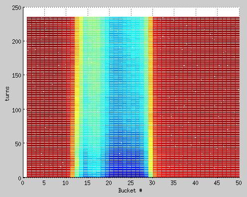
28 SR Filling pattern monitor high sampling rate scope Apr , after IS kicker polarity correction ~ 8 turns in SR 28
29 Apr Beam survives > 150 us 29
30 Three shots 1/3 Hz injection 30

31 Trev = 2.64us 31

32 Trf = 2ns 20 bunches gun pulse width 40ns 32

33 Apr Stored beam RF ON, Sext ON On-axis injection 33

34 Apr Stored beam, poor accumulation Off-axis injection 34

35 Captured on Apr-11, after Booster energy and SR RF phase adjusted, didn't see the dip on BPM raw button SUM signal. The reason we saw dip is because: longitudinal large oscillation filament => effective bunch length increase => SUM signal decrease. After radiation damping, bunch length decrease => SUM signal recovered. 35
36 Apr , after fixing RF spring in C10 Off-axis injection 36

37 37
38 Apr Three shots 1/3Hz injection 38

39 18 bunches Stored beam ~1.58mA. 18 bunches with e-gun pulse width set to 35ns 39
40 Camshaft filling pattern There was 0.6mA in the single bunch and 13.1mA in 1000 bunches. Reflection signal from single bunch 40

41 4-bunch train, 80% fill, Itotal = 22mA 41
42 ~ 47mA, one bunch train, 80% fill 42


43 FPM to measure synchronous phase 2014-Jul-13 data, use FPM to measure synchronous phase at various Vrf, keep the current same and filling pattern. I = 2.1mA, 20- bunches in one bunch train. 43


44 φ s = 0 + φ - measured phase m φ - constant due todelays 0 φ - synchronous phase s φ φ m ev sinφ = U = U + U rf s At low current, neglect parasitic energy loss sr pm ev rf x = ev rf y = ev sinφ cosφ + ev rf m y cosφ + xsinφ = U 0 cosφ sinφ m m 0 0 rf s cosφ sinφ = U m 0 sr Measured energy loss per turn was kv 287 kv from ideal lattice, w/o DW. Within 5% difference 44
45 3. Profile monitors (Flags, visible SLM, x-ray diagnostics) 45


46 Profile monitor injector flags Mar , ~21:40 injection beam passing through pulse septum on IS flag - 10 x 10 mm square visible - Circle should be vacuum window - Beam image and some reflections BtS BDVF2, OTR Energy jitter and energy spread measurement, using LtB VF2. 46


47 Profile monitors - Booster SLM #1 #2 #3 #4 #5 #6 #7 #8 #9 #10 10 burst images acquired on the same booster ramp cycle, separate by 40ms 47


48 Profile monitors Visible SLM TUPF21 First turn image Apr First several turns profile captured using gated camera after injection kicker ~ 1.5mA stored beam 48


49 0.22mA Streak camera measurements Profile at Vrf = 1200kV Height scaled to bunch current Alpha = e-04 % momentum compaction factor SigE = e-04 % relative energy spread α σ E fromσ t =, we know 2πf E σ f t s s α σ E = = 2.97e -8 2π E 49
50 4. Other diagnostics (TMS, BxB feedback, FFT spectrum etc.) 50


51 Beam spectrum and tune Fx = 87.5kHz, vx = Fy = 70.3kHz, vy = Fs = 2.7kHz, vs = Vrf = 1.89 MV Methods to measure tunes - FFT spectrum with pulse kicker - BPM TbT Fourier spectrum with pulse kicker - TMS network analyzer with sweeping excitation - BxB feedback spectrum or transfer function - Others (phase advance, LOCO etc) 51


52 TMS sweeping tune measurement TMS measures betatron tune with 1e-4 resolution Worked fine at very low current, 0.1mA in multi-bunches NA sweep time 1-2 seconds 15cm stripline kicker, 75W broadband amplifiers 1 st order chromaticy X/Y = ; ξξ = Δνν ΔE = αα cc EE Δνν Δff ff 52


53 BxB feedback commissioning WEPD27 30 cm plate Ceramic Single bunch, I_b = 4.5mA Y plane growth-damp measurement, feedback OFF for 3ms and recaptures I = 44mA, stored beam, C30 BPM1 FB OFF FB ON 53


54 Single bunch transfer function measurement khz/ma or /mA Vertical plane tune spectrum at different single bunch current looks like TMCI Horizontal plane peak position doesn t move much kHz/mA (0.0077/mA) slope, agrees with other method results. 3dB bandwidth increasing as the single bunch current increased. 54

55 Unstable modes analysis, 1024 turns data of 1320 buckets m=-3 m=-9 55


56 Compare BPM TbT spectrum with BxB ON/OFF Data at around 2014Jul11_2040, I ~44mA Red Feedback OFF Blue Feedback ON > 30 db suppression of betatron motions sideband 56
57 Summary 50mA stored beam achieved in NSLS2 storage ring, with SC RF cavity ID commissioning, higher current high stability beam will continue in coming months Most of NSLS2 diagnostics have been commissioned with beam. Machine characterized and optimized using these powerful tools. These diagnostics will play important roles for further understanding and development of the machine. Some highlights include: Beam motion measured to be ~ 2um RMS (< khz) Reliable current and lifetime measurement First synchrotron light on the NSLS2 experiment floor (visible light) Single bunch and coupled bunch instabilities suppression NSLS2 contributions at the conference: MOPF03 NSLSII Photon Beam Position Monitor Testing MOPF07 Construction and Operational Performance of a Horizontally Adjustable Beam Profile Monitor at NSLS-II MOPF20 Diagnosing NSLS-II -- the World's Most Advanced Synchrotron Light Source TUPF01 NSLS-II RF Beam Position Monitor- System Test and Integration TUPF21 NSLS2 Visible Synchrotron Light Monitor Diagnostic Beamline Commissioning WECYB2 NSLS-II RF Beam Position Monitor Commissioning Update WEPD27 Commissioning of Bunch-by-Bunch Feedback System for NSLS2 Storage Ring Thanks for those who design, build, test and commissioned the machine. Thanks for outside experts for various reviews, discussion, collaboration and helps. 57
SPEAR 3: Operations Update and Impact of Top-Off Injection
 SPEAR 3: Operations Update and Impact of Top-Off Injection R. Hettel for the SSRL ASD 2005 SSRL Users Meeting October 18, 2005 SPEAR 3 Operations Update and Development Plans Highlights of 2005 SPEAR 3
Status of SOLARIS Arkadiusz Kisiel
 Status of SOLARIS Arkadiusz Kisiel Solaris National Synchrotron Light Source Jagiellonian University Czerwone Maki 98 30-392 Kraków www.synchrotron.uj.edu.pl Arkadiusz.Kisiel@uj.edu.pl On behalf of SOLARIS
The Elettra Storage Ring and Top-Up Operation
 The Elettra Storage Ring and Top-Up Operation Emanuel Karantzoulis Past and Present Configurations 1994-2007 From 2008 5000 hours /year to the users 2010: Operations transition year Decay mode, 2 GeV (340mA)
PEP II Design Outline
 PEP II Design Outline Balša Terzić Jefferson Lab Collider Review Retreat, February 24, 2010 Outline General Information Parameter list (and evolution), initial design, upgrades Collider Ring Layout, insertions,
Accelerator Systems of the TPS
 Ambient Ground Motion and Civil Engineering for Low Emittance Electron Storage Ring July 2-22, 2005, Hsinchu, Taiwan Accelerator Systems of the TPS Preinjector, Booster Synchrotron, Transfer Line, and
The basic parameters of the pre-injector are listed in the Table below. 100 MeV
 3.3 The Pre-injector The high design brightness of the SLS requires very high phase space density of the stored electrons, leading to a comparatively short lifetime of the beam in the storage ring. This,
Diamond RF Status (RF Activities at Daresbury) Mike Dykes
 Mike Dykes") Diamond RF Status (RF Activities at Daresbury) Mike Dykes ASTeC What is it? What does it do? Diamond Status Linac Booster RF Storage Ring RF Summary Content ASTeC ASTeC was formed in 2001 as a centre of
Diamond RF Status (RF Activities at Daresbury) Mike Dykes ASTeC What is it? What does it do? Diamond Status Linac Booster RF Storage Ring RF Summary Content ASTeC ASTeC was formed in 2001 as a centre of
Digital BPMs and Orbit Feedback Systems
 Digital BPMs and Orbit Feedback Systems, M. Böge, M. Dehler, B. Keil, P. Pollet, V. Schlott Outline stability requirements at SLS storage ring digital beam position monitors (DBPM) SLS global fast orbit
Status of Elettra, top-up and other upgrades
 Status of Elettra, top-up and other upgrades Emanuel Karantzoulis ELETTRA / Trieste, Italy / 2010 November 25-26 Past and Present Configurations 1994-2007 From 2008 No full energy injection Full energy
New Filling Pattern for SLS-FEMTO
 SLS-TME-TA-2009-0317 July 14, 2009 New Filling Pattern for SLS-FEMTO Natalia Prado de Abreu, Paul Beaud, Gerhard Ingold and Andreas Streun Paul Scherrer Institut, CH-5232 Villigen PSI, Switzerland A new
NSLS-II RF BEAM POSITION MONITOR COMMISSIONING UPDATE
 NSLS-II RF BEAM POSITION MONITOR COMMISSIONING UPDATE Joseph Mead#, Anthony Caracappa, Weixing Cheng, Christopher Danneil, Joseph DeLong, Al DellaPenna, Kiman Ha, Bernard Kosciuk, Marshall Maggipinto,
Top-Up Experience at SPEAR3
 Top-Up Experience at SPEAR3 Contents SPEAR 3 and the injector Top-up requirements Hardware systems and modifications Safety systems & injected beam tracking Interlocks & Diagnostics SPEAR3 Accelerator
LHC Beam Instrumentation Further Discussion
 LHC Beam Instrumentation Further Discussion LHC Machine Advisory Committee 9 th December 2005 Rhodri Jones (CERN AB/BDI) Possible Discussion Topics Open Questions Tune measurement base band tune & 50Hz
LCLS RF Reference and Control R. Akre Last Update Sector 0 RF and Timing Systems
 LCLS RF Reference and Control R. Akre Last Update 5-19-04 Sector 0 RF and Timing Systems The reference system for the RF and timing starts at the 476MHz Master Oscillator, figure 1. Figure 1. Front end
Summary of the 1 st Beam Line Review Meeting Injector ( )
") Summary of the 1 st Beam Line Review Meeting Injector (23.10.2006) 15.11.2006 Review the status of: beam dynamics understanding and simulations completeness of beam line description conceptual design of
Summary of the 1 st Beam Line Review Meeting Injector (23.10.2006) 15.11.2006 Review the status of: beam dynamics understanding and simulations completeness of beam line description conceptual design of
North Damping Ring RF
 North Damping Ring RF North Damping Ring RF Outline Overview High Power RF HVPS Klystron & Klystron EPICS controls Cavities & Cavity Feedback SCP diagnostics & displays FACET-specific LLRF LLRF distribution
Characterizing Transverse Beam Dynamics at the APS Storage Ring Using a Dual-Sweep Streak Camera
 Characterizing Transverse Beam Dynamics at the APS Storage Ring Using a Dual-Sweep Streak Camera Bingxin Yang, Alex H. Lumpkin, Katherine Harkay, Louis Emery, Michael Borland, and Frank Lenkszus Advanced
SSRF Beam Diagnostics Commissioning. LENG Yongbin on behalf of SSRF BI group
 SSRF Beam Diagnostics Commissioning LENG Yongbin on behalf of SSRF BI group 2009.05.25 Outline Instruction of SSRF Overview of SSRF BI system Subsystem Beam position monitor Tune monitor Current & charge
Production of quasi-monochromatic MeV photon in a synchrotron radiation facility
 Production of quasi-monochromatic MeV photon in a synchrotron radiation facility Presentation at University of Saskatchewan April 22-23, 2010 Yoshitaka Kawashima Brookhaven National Laboratory NSLS-II,
4.4 Injector Linear Accelerator
 4.4 Injector Linear Accelerator 100 MeV S-band linear accelerator based on the components already built for the S-Band Linear Collider Test Facility at DESY [1, 2] will be used as an injector for the CANDLE
Bunch-by-bunch feedback and LLRF at ELSA
 Bunch-by-bunch feedback and LLRF at ELSA Dmitry Teytelman Dimtel, Inc., San Jose, CA, USA February 9, 2010 Outline 1 Feedback Feedback basics Coupled-bunch instabilities and feedback Beam and feedback
Photoinjector Laser Operation and Cathode Performance
 Photoinjector Laser Operation and Cathode Performance Daniele Sertore, INFN Milano LASA Siegfried Schreiber, DESY Laser operational experience Laser beam properties Cathode performances Outlook TTF and
P. Emma, et al. LCLS Operations Lectures
 P. Emma, et al. LCLS Operations Lectures LCLS 1 LCLS Accelerator Schematic 6 MeV 135 MeV 250 MeV σ z 0.83 mm σ z 0.83 mm σ z 0.19 mm σ δ 0.05 % σ δ 0.10 % σ δ 1.6 % Linac-0 L =6 m rf gun L0-a,b Linac-1
COMMISSIONING SCENARIOS FOR THE J-PARC ACCELERATOR COMPLEX
 COMMISSIONING SCENARIOS FOR THE J-PARC ACCELERATOR COMPLEX T. Koseki, M. Ikegami, M. Tomizawa, Accelerator Laboratory, KEK, Tsukuba, Japan F. Noda, JAEA, Tokai, Japan Abstract The J-PARC (Japan Proton
PEP II STATUS AND PLANS *
 PEP II STATUS AND PLANS * John T. Seeman + Stanford Linear Accelerator Center, Stanford University, Stanford, CA 94309 USA The PEP II B-Factory 1 project is an e + e - colliding beam storage ring complex
Current status of XFEL/SPring-8 project and SCSS test accelerator
 Current status of XFEL/SPring-8 project and SCSS test accelerator Takahiro Inagaki for XFEL project in SPring-8 inagaki@spring8.or.jp Outline (1) Introduction (2) Key technology for compactness (3) Key
Precision measurements of beam current, position and phase for an e+e- linear collider
 Precision measurements of beam current, position and phase for an e+e- linear collider R. Corsini on behalf of H. Braun, M. Gasior, S. Livesley, P. Odier, J. Sladen, L. Soby INTRODUCTION Commissioning
Beam Instrumentation for X-ray FELs
 Beam Instrumentation for X-ray FELs 05/16/2011 1 1 Outline X-ray FEL overview Diagnostics requirements for X-ray FELs Transverse Diagnostics Longitudinal Diagnostics Summary 2 2 X-ray FEL Overview 100
Linac 4 Instrumentation K.Hanke CERN
 Linac 4 Instrumentation K.Hanke CERN CERN Linac 4 PS2 (2016?) SPL (2015?) Linac4 (2012) Linac4 will first inject into the PSB and then can be the first element of a new LHC injector chain. It will increase
CONSTRUCTION AND COMMISSIONING OF BEPCII
 Abstract CONSTRUCTION AND COMMISSIONING OF BEPCII C. Zhang, J.Q. Wang, L. Ma and G.X.Pei for the BEPCII Team, IHEP, CAS P.O.Box 918, Beijing 100049, China BEPCII is the major upgrade of BEPC (Beijing Electron-
Development of an Abort Gap Monitor for High-Energy Proton Rings *
 Development of an Abort Gap Monitor for High-Energy Proton Rings * J.-F. Beche, J. Byrd, S. De Santis, P. Denes, M. Placidi, W. Turner, M. Zolotorev Lawrence Berkeley National Laboratory, Berkeley, USA
Future Performance of the LCLS
 Future Performance of the LCLS J. Welch for many* SLAC National Accelerator Laboratory FLS 2010, ICFA Beam Dynamics Workshop on Future Light Sources, March 1-5, 2010. SLAC National Accelerator Laboratory,
OPERATIONAL EXPERIENCE AT J-PARC
 OPERATIONAL EXPERIENCE AT J-PARC Hideaki Hotchi, ) for J-PARC commissioning team ), 2), ) Japan Atomic Energy Agency (JAEA), Tokai, Naka, Ibaraki, 39-95 Japan, 2) High Energy Accelerator Research Organization
PEP-II STATUS REPORT *
 PEP-II STATUS REPORT * Jonathan Dorfan Stanford Linear Accelerator Center, Stanford University, Stanford, CA 94309 USA For the SLAC, LBNL, LLNL PEP-II group Abstract The main design features of the PEP-II
Experience with the Cornell ERL Injector SRF Cryomodule during High Beam Current Operation
 Experience with the Cornell ERL Injector SRF Cryomodule during High Beam Current Operation Matthias Liepe Assistant Professor of Physics Cornell University Experience with the Cornell ERL Injector SRF
30 GHz Power Production / Beam Line
 30 GHz Power Production / Beam Line Motivation & Requirements Layout Power mode operation vs. nominal parameters Beam optics Achieved performance Problems Beam phase switch for 30 GHz pulse compression
COMMISSIONING RESULTS OF BEAM DIAGNOSTICS FOR THE PETRA III LIGHT SOURCE
 Proceedings of DIPAC9, Basel, Switzerland MOOB2 COMMISSIONING RESULTS OF BEAM DIAGNOSTICS FOR THE PETRA III LIGHT SOURCE K. Balewski #, G. Kube, K. Wittenburg, A. Brenger, H.-T. Duhme, V. Gharibyan, J.
Status of RF Power and Acceleration of the MAX IV - LINAC
 Status of RF Power and Acceleration of the MAX IV - LINAC Dionis Kumbaro ESLS RF Workshop 2015 MAX IV Laboratory A National Laboratory for synchrotron radiation at Lunds University 1981 MAX-lab is formed
Accelerator Instrumentation RD. Monday, July 14, 2003 Marc Ross
 Monday, Marc Ross Linear Collider RD Most RD funds address the most serious cost driver energy The most serious impact of the late technology choice is the failure to adequately address luminosity RD issues
Present Status and Future Upgrade of KEKB Injector Linac
 Present Status and Future Upgrade of KEKB Injector Linac Kazuro Furukawa, for e /e + Linac Group Present Status Upgrade in the Near Future R&D towards SuperKEKB 1 Machine Features Present Status and Future
Requirements for the Beam Abort Magnet and Dump
 Requirements for the Beam Abort Magnet and Dump A beam abort kicker (pulsed dipole magnet) and dump are required upbeam of the LCLS undulator in order to protect the undulator from mis-steered and poor
The Construction Status of CSNS Linac
 The Construction Status of CSNS Linac Sheng Wang Dongguan branch, Institute of High Energy Physics, CAS Sep.2, 2014, Geneva Outline The introduction to CSNS accelerators The commissoning of ion source
Phase (deg) Phase (deg) Positive feedback, 317 ma. Negative feedback, 330 ma. jan2898/1638: beam pseudospectrum around 770*frev.
 Phase (deg) Positive feedback, 317 ma. Negative feedback, 330 ma. jan2898/1638: beam pseudospectrum around 770*frev.") Commissioning Experience from PEP-II HER Longitudinal Feedback 1 S. Prabhakar, D. Teytelman, J. Fox, A. Young, P. Corredoura, and R. Tighe Stanford Linear Accelerator Center, Stanford University, Stanford,
Commissioning Experience from PEP-II HER Longitudinal Feedback 1 S. Prabhakar, D. Teytelman, J. Fox, A. Young, P. Corredoura, and R. Tighe Stanford Linear Accelerator Center, Stanford University, Stanford,
Hall-B Beamline Commissioning Plan for CLAS12
 Hall-B Beamline Commissioning Plan for CLAS12 Version 1.5 S. Stepanyan December 19, 2017 1 Introduction The beamline for CLAS12 utilizes the existing Hall-B beamline setup with a few modifications and
First Simultaneous Top-up Operation of Three Different Rings in KEK Injector Linac
 First Simultaneous Top-up Operation of Three Different Rings in KEK Injector Linac Masanori Satoh (Acc. Lab., KEK) for the injector upgrade group 2010/9/16 1 Overview of Linac Beam Operation 2010/9/16
Proton Engineering Frontier Project
 Proton Engineering Frontier Project OECD Nuclear Energy Agency Fifth International Workshop on the Utilisation and Reliability of High Power Proton Accelerators (HPPA5) (6-9 May 2007, Mol, Belgium) Yong-Sub
Non-Invasive Energy Spread Monitoring for the JLAB Experimental Program via Synchrotron Light Interferometers
 Non-Invasive for the JLAB Experimental Program via Synchrotron Light Interferometers P. Chevtsov, T. Day, A.P. Freyberger, R. Hicks Jefferson Lab J.-C. Denard Synchrotron SOLEIL 20th March 2005 1. Energy
ABORT DIAGNOSTICS AND ANALYSIS DURING KEKB OPERATION
 ABORT DIAGNOSTICS AND ANALYSIS DURING KEKB OPERATION H. Ikeda*, J. W. Flanagan, T. Furuya, M. Tobiyama, KEK, Tsukuba, Japan M. Tanaka, MELCO SC,Tsukuba, Japan Abstract KEKB has stopped since June 2010
The FLASH objective: SASE between 60 and 13 nm
 Injector beam control studies winter 2006/07 talk from E. Vogel on work performed by W. Cichalewski, C. Gerth, W. Jalmuzna,W. Koprek, F. Löhl, D. Noelle, P. Pucyk, H. Schlarb, T. Traber, E. Vogel, FLASH
Operational Status of PF-Ring and PF-AR after the Earthquake
 Journal of Physics: Conference Series Operational Status of PF-Ring and PF-AR after the Earthquake To cite this article: T Honda et al 2013 J. Phys.: Conf. Ser. 425 042014 Related content - Design and
Photo cathode RF gun -
 Photo cathode RF gun - *),,, ( 05 Nov. 2004 Spring8 UTNL Linac & Mg Photocathode RF Gun Mg photocathode NERL, 18 MeV Linac and the RF gun Electron Beam Mg photocathode Mg photocathode RF gun of SPring8
Upgrading LHC Luminosity
 1 Upgrading LHC Luminosity 2 Luminosity (cm -2 s -1 ) Present (2011) ~2 x10 33 Beam intensity @ injection (*) Nominal (2015?) 1 x 10 34 1.1 x10 11 Upgraded (2021?) ~5 x10 34 ~2.4 x10 11 (*) protons per
ANKA Status Report. N.Smale, A.-S. Müller, E. Huttel, M.Schuh Slides courtesy of A.-S. Müller and C.Heske.
 ANKA Status Report N.Smale, A.-S. Müller, E. Huttel, M.Schuh Slides courtesy of A.-S. Müller and C.Heske. KIT - University of the State of Baden-Wuerttemberg and National Laboratory of the Helmholtz Association
TWO BUNCHES WITH NS-SEPARATION WITH LCLS*
 TWO BUNCHES WITH NS-SEPARATION WITH LCLS* F.-J. Decker, S. Gilevich, Z. Huang, H. Loos, A. Marinelli, C.A. Stan, J.L. Turner, Z. van Hoover, S. Vetter, SLAC, Menlo Park, CA 94025, USA Abstract The Linac
Detailed Design Report
 Detailed Design Report Chapter 4 MAX IV Injector 4.6. Acceleration MAX IV Facility CHAPTER 4.6. ACCELERATION 1(10) 4.6. Acceleration 4.6. Acceleration...2 4.6.1. RF Units... 2 4.6.2. Accelerator Units...
ALBA. Libera Workshop 16 A. Olmos
 LIBERAs @ ALBA Libera Workshop 16 A. Olmos Content Fast Orbit Feedback At a glance Equipments Implementation Limitations In operation Bunch-by- Bunch system At a glance Ported Software Status What else
CLIC Feasibility Demonstration at CTF3
 CLIC Feasibility Demonstration at CTF3 Roger Ruber Uppsala University, Sweden, for the CLIC/CTF3 Collaboration http://cern.ch/clic-study LINAC 10 MO303 13 Sep 2010 The Key to CLIC Efficiency NC Linac for
LCLS Injector Technical Review
 LCLS Injector Technical Review Stanford Linear Accelerator Center November 3&4 2003 Review Committee Members: Prof. Patrick O Shea Chair University of Maryland Dr. E. Colby Stanford Linear Accelerator
Beam Loss Detection for MPS at FRIB
 Beam Loss Detection for MPS at FRIB Zhengzheng Liu Beam Diagnostics Physicist This material is based upon work supported by the U.S. Department of Energy Office of Science under Cooperative Agreement DE-SC0000661.
Introduction to Synchrotron Radiation and Storage Ring Light Sources.
 Introduction to Synchrotron Radiation and Storage Ring Light Sources. Monday 22 Nov 2010 at 12:15 (00h55') Primary authors : Dr. PODOBEDOV, Boris (BNL) Co-authors : Presenter : Dr. PODOBEDOV, Boris (BNL)
Recent APS Storage Ring Instrumentation Developments. Glenn Decker Advanced Photon Source Beam Diagnostics March 1, 2010
 Recent APS Storage Ring Instrumentation Developments Glenn Decker Advanced Photon Source Beam Diagnostics March 1, 2010 Ring Diagnostics Overview RF beam position monitor technology Photon beam position
beam dump from P2 losses this morning
 beam dump from P2 losses this morning Some observations on the beam dump from P2 losses this morning 29.10.10 at 01:26:39: - single bunch intensity (average) was ~1.3e11 - significantly higher than previous
Position Resolution of Optical Fibre-Based Beam Loss Monitors using long electron pulses
 Position Resolution of Optical Fibre-Based Beam Loss Monitors using long electron pulses E. Nebot del Busto (1,2, 3), M. J. Boland (4,5), S. Doebert (1), F. S. Domingues (1), E. Effinger (1), W. Farabolini
Status of SOLARIS. Paweł Borowiec On behalf of Solaris Team
 Status of SOLARIS Paweł Borowiec On behalf of Solaris Team e-mail: pawel.borowiec@uj.edu.pl XX ESLS-RF Meeting, Villingen 16-17.11.2016 Outline 1. Timeline 2. Injector 3. Storage ring 16-17.11.2016 XX
A Facility for Accelerator Physics and Test Beam Experiments
 A Facility for Accelerator Physics and Test Beam Experiments U.S. Department of Energy Review Roger Erickson for the FACET Design Team February 20, 2008 SLAC Overview with FACET FACET consists of four
PEP-II longitudinal feedback and the low groupdelay. Dmitry Teytelman
 PEP-II longitudinal feedback and the low groupdelay woofer Dmitry Teytelman 1 Outline I. PEP-II longitudinal feedback and the woofer channel II. Low group-delay woofer topology III. Why do we need a separate
TECHNIQUES FOR OBSERVING BEAM DYNAMICAL EFFECTS CAUSED BY THE PRESENCE OF ELECTRON CLOUDS*
 Proceedings of ECLOUD10, Ithaca, New York, USA TECHNIQUES FOR OBSERVING BEAM DYNAMICAL EFFECTS CAUSED BY THE PRESENCE OF ELECTRON CLOUDS* M. Billing, G. Dugan, R. Meller, M. Palmer, G. Ramirez, J. Sikora,
BUNCH BY BUNCH FEEDBACK SYSTEMS FOR SUPERKEKB RINGS
 August 8-1, 216, Chiba, Japan PASJ216 TUOM6 BUNCH BY BUNCH FEEDBACK SYSTEMS FOR SUPERKEKB RINGS Makoto Tobiyama, John W. Flanagan, KEK Accelerator Laboratory, 1-1 Oho, Tsukuba 35-81, Japan, and Graduate
Fast Orbit Feedback at the SLS. Outline
 Fast Orbit Feedback at the SLS 2nd Workshop on Beam Orbit Stabilisation (December4-6, 2002, SPring-8) T. Schilcher Outline Noise Sources at SLS Stability / System Requirements Fast Orbit Feedback Implementation
IOT OPERATIONAL EXPERIENCE ON ALICE AND EMMA AT DARESBURY LABORATORY
 IOT OPERATIONAL EXPERIENCE ON ALICE AND EMMA AT DARESBURY LABORATORY A. Wheelhouse ASTeC, STFC Daresbury Laboratory ESLS XVIII Workshop, ELLETRA 25 th 26 th November 2010 Contents Brief Description ALICE
Jae-Young Choi On behalf of PLS-II Linac team
 PLS-II Linac 2015. 4. 8. Jae-Young Choi On behalf of PLS-II Linac team Accelerators in Pohang Accelerator Laboratory XFEL (under construction) 400 M$ Machines under installation PLS-II PAL : Chronology
3 cerl. 3-1 cerl Overview. 3-2 High-brightness DC Photocathode Gun and Gun Test Beamline
 3 cerl 3-1 cerl Overview As described before, the aim of the cerl in the R&D program includes the development of critical components for the ERL, as well as the construction of a test accelerator. The
Sérgio Rodrigo Marques
 Sérgio Rodrigo Marques (on behalf of the beam diagnostics group) sergio@lnls.br Outline Introduction Stability Requirements General System Requirements FOFB Strategy Hardware Overview Performance Tests:
Operational experience with the SOLEIL LINAC and Status of the ThomX LINAC project
 Operational experience with the SOLEIL LINAC and Status of the ThomX LINAC project 16/11/2016 20th ELS-RF Workshop Pollina JP 1 and Status of the ThomX LINAC project Operational experience with the SOLEIL
LHC Nominal injection sequence
 LHC Nominal injection sequence Mike Lamont Acknowledgements: Reyes Alemany Fernandez, Brennan Goddard Nominal injection Overall injection scheme Pilot R1, Pilot R2, Intermediate R1 Optimise Intermediate
The PEFP 20-MeV Proton Linear Accelerator
 Journal of the Korean Physical Society, Vol. 52, No. 3, March 2008, pp. 721726 Review Articles The PEFP 20-MeV Proton Linear Accelerator Y. S. Cho, H. J. Kwon, J. H. Jang, H. S. Kim, K. T. Seol, D. I.
Monthly Progress Report Stanford Synchrotron Radiation Laboratory
 Monthly Progress Report Stanford Synchrotron Radiation Laboratory April 2003 TABLE OF CONTENTS A. Project Summary 1. Technical Progress 3 2. Cost Data 5 B. Design and Fabrication Reports 1.1 Magnets &
Linac-Beam Characterizations at 600 MeV Using Optical Transition Radiation Diagnostics *
 Linac-Beam Characterizations at 6 MeV Using Optical Transition Radiation Diagnostics * A. H. Lumpkin, W. J. Berg, B. X. Yang, and M. White Advanced Photon Source, Argonne National Laboratory 97 South Cass
TRANSVERSE DAMPING AND FAST INSTABILITIES
 TRANSVERSE DAMPING AND FAST INSTABILITIES Abstract The characteristics of the LHC beams in the SPS, protons and ions, pose stringent requirements on the SPS damper (feedback system). The boundary conditions
RF considerations for SwissFEL
 RF considerations for H. Fitze in behalf of the PSI RF group Workshop on Compact X-Ray Free Electron Lasers 19.-21. July 2010, Shanghai Agenda Introduction RF-Gun Development C-band development Summary
Periodic Seasonal Variation of Magnets Level of the STB ring
 Periodic Seasonal Variation of Magnets Level of the STB ring Shigenobu Takahashi Laboratory of Nuclear Science,Tohoku University, Mikamine 1-2-1, Taihaku-ku, Sendai 982-0826, Japan 1. Introduction The
KARA and FLUTE RF Overview/status
 KARA and FLUTE RF Overview/status Nigel Smale on behalf of IBPT and LAS teams Laboratory for Applications of Synchrotron radiation (LAS) Institute for Beam Physics and Technology (IBPT) KARA KIT The Research
PEP II Status and Plans
 SLAC-PUB-6854 September 1998 PEP II Status and Plans By John T. Seeman Invited talk presented at the 16th IEEE Particle Accelerator Conference (PAC 95) and International Conference on High Energy Accelerators,
Jefferson Lab Experience with Beam Halo, Beam Loss, etc.
 Jefferson Lab Experience with Beam Halo, Beam Loss, etc. Pavel Evtushenko with a lot of input from many experienced colleagues Steve Benson, Dave Douglas, Kevin Jordan, Carlos Hernandez-Garcia, Dan Sexton,
Beam Instrumentation for CTF3 and CLIC
 Beam Instrumentation for CTF3 and CLIC Beam loss - Beam halo monitoring developments CLIC diagnostic Common developments with other projects Specific requirements for CLIC Beam Loss and Beam Halo measurement
1 Digital BPM Systems for Hadron Accelerators
 Digital BPM Systems for Hadron Accelerators Proton Synchrotron 26 GeV 200 m diameter 40 ES BPMs Built in 1959 Booster TT70 East hall CB Trajectory measurement: System architecture Inputs Principles of
G0 Laser Status Parity Controls Injector Diagnostics
 G0 Laser Status Parity Controls Injector Diagnostics G0 Collaboration Mtg Jefferson Lab August 16, 2002 G0 Collaboration Mtg (August 16, 2002), 1 Installed new AOM homebuilt laser G0 Collaboration Mtg
CLIC Feasibility Demonstration at CTF3
 CLIC Feasibility Demonstration at CTF3 Roger Ruber Uppsala University, Sweden, KVI Groningen 20 Sep 2011 The Key to CLIC Efficiency NC Linac for 1.5 TeV/beam accelerating gradient: 100 MV/m RF frequency:
Screen investigations for low energetic electron beams at PITZ
 1 Screen investigations for low energetic electron beams at PITZ S. Rimjaem, J. Bähr, H.J. Grabosch, M. Groß Contents Review of PITZ setup Screens and beam profile monitors at PITZ Test results Summary
Week 0: PPS Certification and Processing. Mon Feb 11 Tue Feb 12 Wed Feb 13 Thu Feb 14 Fri Feb 15 Sat Feb 16 Sun Feb 17
 Week 0: PPS Certification and Processing Mon Feb 11 Tue Feb 12 Wed Feb 13 Thu Feb 14 Fri Feb 15 Sat Feb 16 Sun Feb 17 Work in tunnel Work in tunnel PPS Certification PPS Certification PPS Certification
ANKA RF System - Upgrade Strategies
 ANKA RF System - Upgrade Strategies Vitali Judin ANKA Synchrotron Radiation Facility 2014-09 - 17 KIT University of the State Baden-Wuerttemberg and National Laboratory of the Helmholtz Association www.kit.edu
LLRF at SSRF. Yubin Zhao
 LLRF at SSRF Yubin Zhao 2017.10.16 contents SSRF RF operation status Proton therapy LLRF Third harmonic cavity LLRF Three LINAC LLRF Hard X FEL LLRF (future project ) Trip statistics of RF system Trip
FIRST SIMULTANEOUS TOP-UP OPERATION OF THREE DIFFERENT RINGS IN KEK INJECTOR LINAC
 FIRST SIMULTANEOUS TOP-UP OPERATION OF THREE DIFFERENT RINGS IN KEK INJECTOR LINAC M. Satoh #, for the IUC * Accelerator Laboratory, High Energy Accelerator Research Organization (KEK) 1-1 Oho, Tsukuba,
Beam Diagnostics for the BNL Energy Recovery Linac Test Facility
 Beam Diagnostics for the BNL Energy Recovery Linac Test Facility Peter Cameron, Ilan Ben-Zvi, Michael Blaskiewicz, Michael Brennan, Roger Connolly, William Dawson, Chris Degen, Al DellaPenna, David Gassner,
LIGHT PROTON THERAPY PROJECT
 17 th of MAY 2018 LIGHT PROTON THERAPY PROJECT Yevgeniy Ivanisenko on behalf of ADAM team FORM-01040-A AVO-ADAM Advanced Oncotherapy (AVO) is a public company ADAM is R&D center of AVO ~ 100 employees
PRESENT STATUS OF J-PARC
 PRESENT STATUS OF J-PARC # F. Naito, KEK, Tsukuba, Japan Abstract Japan Proton Accelerator Research Complex (J-PARC) is the scientific facility with the high-intensity proton accelerator aiming to realize
ILC Damping Ring Lattice Status Report. Louis Emery and Aimin Xiao Argonne National Laboratory Presented at KEK workshop Dec 18th, 2007
 Status Report Louis Emery and Aimin Xiao Argonne National Laboratory Presented at KEK workshop Dec 18th, 2007 Outline New 8-fold symmetric lattice on ILC Cornell wiki pages, as of 12/18/2007 Separated
Commissioning of Accelerators. Dr. Marc Munoz (with the help of R. Miyamoto, C. Plostinar and M. Eshraqi)
") Commissioning of Accelerators Dr. Marc Munoz (with the help of R. Miyamoto, C. Plostinar and M. Eshraqi) www.europeanspallationsource.se 6 July, 2017 Contents General points Definition of Commissioning
Commissioning of Accelerators Dr. Marc Munoz (with the help of R. Miyamoto, C. Plostinar and M. Eshraqi) www.europeanspallationsource.se 6 July, 2017 Contents General points Definition of Commissioning
Status of the Jefferson Lab Polarized Beam Physics Program and Preparations for Upcoming Parity Experiments
 Status of the Jefferson Lab Polarized Beam Physics Program and Preparations for Upcoming Parity Experiments P. Adderley, M. Baylac, J. Clark, A. Day, J. Grames, J. Hansknecht, M. Poelker, M. Stutzman PESP
Activities on FEL Development and Application at Kyoto University
 Activities on FEL Development and Application at Kyoto University China-Korea-Japan Joint Workshop on Electron / Photon Sources and Applications Dec. 2-3, 2010 @ SINAP, Shanghai Kai Masuda Inst. Advanced