Polarized Source Development Run Results
|
|
|
- Domenic Lawrence
- 5 years ago
- Views:
Transcription
1 Polarized Source Development Run Results Riad Suleiman Injector Group November 18, 2008
2 Outline Injector Parity DAQ and Helicity Board Pockels Cell Alignment Fast Helicity Reversal Studies: o 30 Hz, 250 Hz and 1 khz BPMs Electronics Search for 60 Hz Noise Halls A & C Beams Crosstalk Summary and Future Parity Beam Studies Thanks to: Roger Flood, Pete Francis, Paul King, Bob Michaels, Julie Roche

3
4 Notes: 1. For each BPM, the wires are: +X+, +X-, +Y+, +Y-. 2. BPM 0R06 is not connected yet. 3. There are only two injector BPMs we are not reading: 0R03 and 0R04. ADC1 Chan 1 Chan 2 Chan 3 Chan 4 Chan 5 Chan 6 Chan 7 Chan 8 QPD pm QPD pp QPD mm QPD mp ADC2 1I02 1I04 ADC3 1I06 0I02 ADC4 0I02A 0I05 ADC5 0I07 0L01 ADC6 0L02 0L03 ADC7 0L04 0L05 ADC8 0L06 0L07 ADC9 0L08 0L09 ADC10 0L10 0R01 ADC11 0R02 0R05 ADC12 0R06 BCM 0L02 Battery 3 Battery 1 Battery 4 Battery 2 Phase Monitor

 Halls and Mott Polarimeters 4.")
5 Helicity Board Outputs (Fiber-optic Signals): 1. Real time helicity Helicity Magnets, Pockels Cell and IA s 2. QRT Halls and Mott Polarimeters 3. MPS (T_Settle) Halls and Mott Polarimeters 4. Reporting Helicity Halls, Mott Polarimeters, iocse9 and iocse14 5. Pair Sync Halls and Mott Polarimeters
6 Helicity Board Software 1. We only have two choices of helicity reversal rates at any given time: 30 Hz and 250 Hz or 30 Hz and 1 khz. 2. To change the helicity reversal rate, a new code must be uploaded in the field to the helicity ioc 3. For both helicity reversal rates, a common choice of T-Settle (4 options): 500, 200, 100, and 60 µs or 500, 100, 60, and 10 µs 4. Reporting Delay: No Delay, 2, 4, or 8 Cycles 5. Helicity Pattern: Pair (+- or -+) or Quartet (-++- or +--+) 6. Helicity Generation: Toggle or Pseudorandom (24-Bit Shift Register that repeats every 13 days at 30 Hz) 7. Free running: for example at 30 Hz, f = 29.xx Hz = 1/(T_Settle+ Integration Window) We are re-designing the Helicity Board
7 Cycle Rae (HZ) MPS (µs) MPS (Hz) QRT (Hz) Helicity (ms) Helicity (Hz) Notes: 1. These values as measured by a scope 2. Signals to Parity DAQ: MPS (T_Settle), QRT, Reporting Helicity, and Pair-Sync 3. The length and frequency of Pair-Sync are identical to Helicity 4. The length of QRT is identical to Helicity 5. The integration window is generated by MPS AND Pair-Sync 6. The integration window for 30 Hz is ms and for 250 Hz it is 3.92 ms
8 Cycle Rae (HZ) MPS (µs) MPS (Hz) QRT (Hz) Helicity (ms) Helicity (Hz) Notes: 1. These values as measured by a scope 2. The integration window for 1 khz is ms
9 Parity ADC Internal Programming (for this study) I. For 30 Hz helicity reversal: Acquisition starts 40 µs after the gate begins There are 4 blocks of 4161 samples/block for each gate. The acquisition time is ms II. For 250 Hz helicity reversal: Acquisition starts 40 µs after the gate begins There are 4 blocks of 485 samples/block for each gate. The acquisition time is ms III. For 1 khz helicity reversal: Acquisition starts 40 µs after the gate begins There are 4 blocks of 117 samples/block for each gate. The acquisition time is 936 µs
10 Battery Signals (3 V) Random, 8-Cycles Delay, Run 361 Bad ADC Channels
11 Battery Signals Battery1 and Battery2 Round Trip to Laser Table Random, 8-Cycles Delay, Run 398 Random, No Delay, Run 406
12 Pockels Cell OFF Random, 8-Cycles Delay, Run 499 No Helicity pickup Random, No Delay, Run 502
13 The Circular polarization = %, and the Linear Polarization = 2.56 % Pockels Cell Alignment The Pockels Cell rise time was measured with a laser beam to be about 80 µs With a Spinning Half Wave Plate or a Spinning Linear Polarizer and a Scope, the Circular polarization was maximized by checking: 1. Laser isogyro pattern 2. Pockels Cell Pitch, Yaw, Roll, X & Y 3. Pockels Cell Voltages The above was checked for IHWP IN and OUT and for 30 Hz and 250 Hz helicity reversal
14
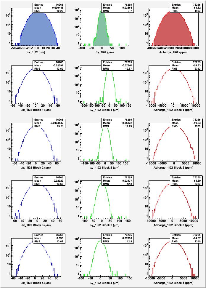
15 T-Settle Study (500, 200, 100, 60 µs) 30 Hz 1. Run 399: PC OFF, IHWP IN, 500 µs 2. Run 381: IHWP OUT, 500 µs 3. Run 382: IHWP IN, 500 µs 4. Run 383: IHWP IN, 200 µs 5. Run 384: IHWP IN, 100 µs 6. Run 385: IHWP IN, 60 µs
16 IA is not OFF BCM0L02 is broken
17 Watch the mean of the 4 distributions
18
19 Total? Block 1 Block 2 Block 3 Block 4
20
21
22
23
24
25
26
27
28
29
30
31
32
33
34
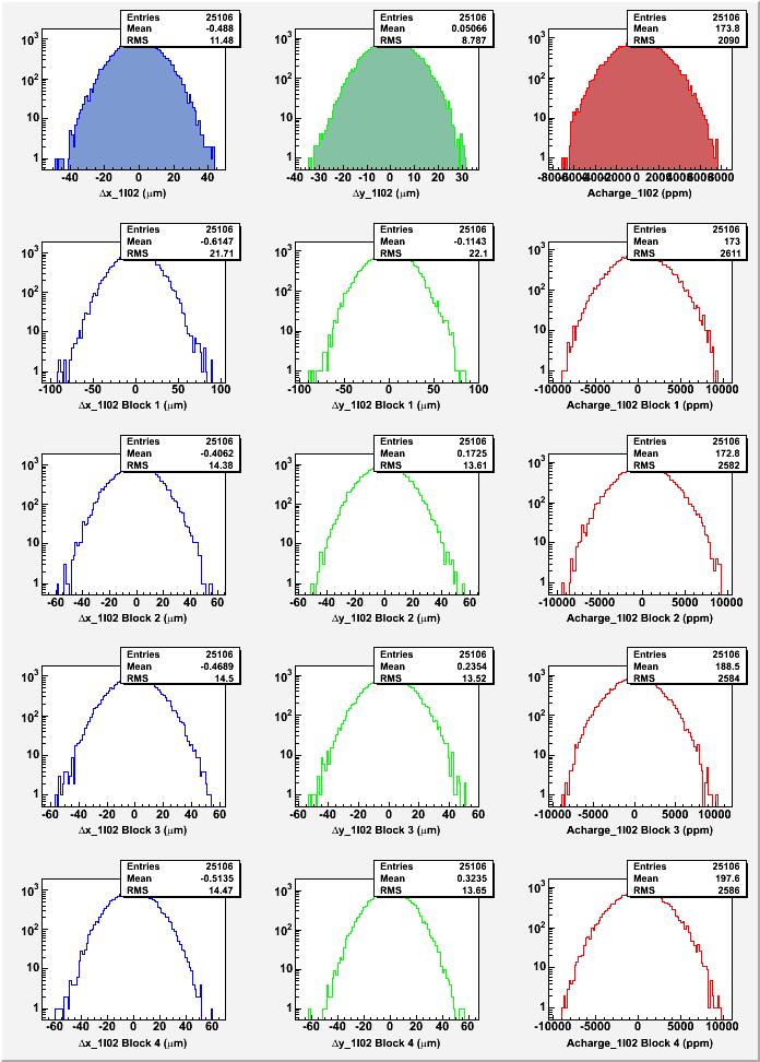
35 T-Settle Study (500, 200, 100, 60 µs) 250 Hz 1. Run 391: PC OFF, IHWP IN, 500 µs 2. Run 394: IHWP OUT, 500 µs 3. Run 392: IHWP IN, 500 µs 4. Run 395: IHWP IN, 200 µs 5. Run 396: IHWP IN, 100 µs 6. Run 397: IHWP IN, 60 µs
36
37 Huge increase in width due to 60 Hz noise
38
39 Huge increase in error due to 60 Hz noise
40
41
42
43
44
45
46
47
48
49
50
51
52
53
54
55
56
57
58 T-Settle Study (500, 100, 60, 10 µs) 1 khz 1. Run 477: PC OFF, IHWP OUT, 100 µs 2. Run 470: IHWP IN, 100 µs 3. Run 471: IHWP OUT, 100 µs Notes: CODA gave error messages with the other T_Settle choices. Problem fixed on November 15, 2008.
59
60
61
62 Modest increase in error due to 60 Hz noise
63
64
65
66
67 Due to BPMs Electronics

68 Due to BPMs Electronics
69
70
71


72 BPMs Electronics Notes: 1. Chan 1: X+, Chan 2: X-, Chan 3: MPS (Trigger) Pockels Cell ON Pockels Cell OFF Pockels Cell ON Pockels Cell OFF
? 1I02, no beam Notes: 1. Hall C iocse18 and iocse14 have TRANSPORT style IF cards 2.")
73 Notes: 1. Injector iocse11, iocse12, and iocse19 have TRANSPORT style IF cards TRANSPORT LINAC Sample Time 140 µs 8.6 µs Fixed Delay 70 µs 4.3 µs Dynamic Range 70 na 200 µa 700 na 2,000 µs 2. To study Pockels Cell Settling Time, should we: Change to LINAC? Use Hall BPMs? Use laser Quad Photodiode (QPD)? 1I02, no beam Notes: 1. Hall C iocse18 and iocse14 have TRANSPORT style IF cards 2. Hall C iocse17 has LINAC style IF cards
74 Search for 60 Hz Noise Did 60 Hz Noise Search with Extech EMF Adapter and a Fluke 87 High reading areas: PSS 500 kev MBO0I06 Dipole current sensor
75 PSS Dipole Magnet 30 Hz 250 Hz 1 khz

76 30 Hz data: 60 Hz noise averaged out

77 Stripe! 250 Hz data: 60 Hz noise maximum

78 1 khz data: 60 Hz noise smaller Correlated because of BPMs Electronics
79 Sensor ON Sensor OFF Sensor ON
80 Sensor ON Sensor OFF Sensor ON
81 Hall A & G0 Cross-talk 1. Hall A IA Scan: Hall A IA Scan (80 ua) Hall C Charge asymmetry and position differences during the Hall A IA Scan (20 ua)
82 2. G0 Charge Asymmetry Width: 20 ua Hall 90 ua 20 ua Hall A OFF
83 Halls A & C Beams Cross-talk Could it be the Surface Charge Limit of the Photo-Cathode Change current and phase of Hall C beam Stop Hall C beam on the Chopper, measure the parity quality of Hall A beam after the Chopper Run 410: Hall A 120 µa, Hall C 0 µa Run 412: Hall A 0 µa, Hall C 110 µa Run 413: Hall A 120 µa, Hall C µa, Hall C laser phase 55 degree Run 414: Hall A 120 µa, Hall C 110 µa, changed Hall C laser phase
84
85
86 Hall C Current Scan
87 Hall C Laser Phase Scan
88 Summary The parity DAQ, BPMs, and Analysis are working fine 30 Hz: The standard PQB at 30 Hz was achieved 250 Hz: The PQB is very similar to 30 Hz otherwise for the 60 Hz noise 1 khz: The PQB is very similar to 30 Hz, again issues with 60 Hz noise (less sensitive than at 250 Hz) BPMs Electronics are affecting T_Settle studies New charge feedback will be implemented: No slow controls (EPICS), zeroed the asymmetry for each of the 4 helicity sequences New Helicity Board design What s next? 1. Finish analysis: 4 blocks, Phase Monitor, Batteries, 2. Study 1 khz for all T_Settle choices 3. More Beams cross-talk studies: with bad QE, IA scans, 4. Eliminate the vacuum window birefringence by rotating the LLGun2 photocathode 5. Check Helicity Magnets, Mott Polarimeters at 1 khz
Parity Quality Beam (PQB) Study
 Study") Parity Quality Beam (PQB) Study Injector Group November 10, 2008 Thanks to: Roger Flood, Pete Francis, Paul King, Bob Michaels, Julie Roche Notes: 1. For each BPM, the wires are: +X+, +X-, +Y+, +Y-. 2.
Parity Quality Beam (PQB) Study Injector Group November 10, 2008 Thanks to: Roger Flood, Pete Francis, Paul King, Bob Michaels, Julie Roche Notes: 1. For each BPM, the wires are: +X+, +X-, +Y+, +Y-. 2.
G0 Laser Status Parity Controls Injector Diagnostics
 G0 Laser Status Parity Controls Injector Diagnostics G0 Collaboration Mtg Jefferson Lab August 16, 2002 G0 Collaboration Mtg (August 16, 2002), 1 Installed new AOM homebuilt laser G0 Collaboration Mtg
Status of the Jefferson Lab Polarized Beam Physics Program and Preparations for Upcoming Parity Experiments
 Status of the Jefferson Lab Polarized Beam Physics Program and Preparations for Upcoming Parity Experiments P. Adderley, M. Baylac, J. Clark, A. Day, J. Grames, J. Hansknecht, M. Poelker, M. Stutzman PESP
PQB Meeting. Caryn Palatchi 02/15/2018
 PQB Meeting Caryn Palatchi 02/15/2018 Previously Planned Improvements to RTP (1) Feedback (2) T Control (3) improved GND isolation Temperature Sensitivity correct with V Fluctuates +-30k ppm, which is
POLARIZED LIGHT SOURCES FOR PHOTOCATHODE ELECTRON GUNS AT SLAC?
 SLAC-PUB-5965 December 1992 (4 POLARIZED LIGHT SOURCES FOR PHOTOCATHODE ELECTRON GUNS AT SLAC? M. Woods,O J. Frisch, K. Witte, M. Zolotorev Stanford Linear Accelerator Center Stanford University, Stanford,
Hall-B Beamline Commissioning Plan for CLAS12
 Hall-B Beamline Commissioning Plan for CLAS12 Version 1.5 S. Stepanyan December 19, 2017 1 Introduction The beamline for CLAS12 utilizes the existing Hall-B beamline setup with a few modifications and
Digital BPMs and Orbit Feedback Systems
 Digital BPMs and Orbit Feedback Systems, M. Böge, M. Dehler, B. Keil, P. Pollet, V. Schlott Outline stability requirements at SLS storage ring digital beam position monitors (DBPM) SLS global fast orbit
Fast Orbit Feedback at the SLS. Outline
 Fast Orbit Feedback at the SLS 2nd Workshop on Beam Orbit Stabilisation (December4-6, 2002, SPring-8) T. Schilcher Outline Noise Sources at SLS Stability / System Requirements Fast Orbit Feedback Implementation
P. Emma, et al. LCLS Operations Lectures
 P. Emma, et al. LCLS Operations Lectures LCLS 1 LCLS Accelerator Schematic 6 MeV 135 MeV 250 MeV σ z 0.83 mm σ z 0.83 mm σ z 0.19 mm σ δ 0.05 % σ δ 0.10 % σ δ 1.6 % Linac-0 L =6 m rf gun L0-a,b Linac-1
IOT OPERATIONAL EXPERIENCE ON ALICE AND EMMA AT DARESBURY LABORATORY
 IOT OPERATIONAL EXPERIENCE ON ALICE AND EMMA AT DARESBURY LABORATORY A. Wheelhouse ASTeC, STFC Daresbury Laboratory ESLS XVIII Workshop, ELLETRA 25 th 26 th November 2010 Contents Brief Description ALICE
RUNNING EXPERIENCE OF FZD SRF PHOTOINJECTOR
 RUNNING EXPERIENCE OF FZD SRF PHOTOINJECTOR Rong Xiang On behalf of the BESSY-DESY-FZD-MBI collaboration and the ELBE team FEL 2009, Liverpool, United Kingdom, August 23 ~ 28, 2009 Outline Introduction
An Overview of Beam Diagnostic and Control Systems for AREAL Linac
 An Overview of Beam Diagnostic and Control Systems for AREAL Linac Presenter G. Amatuni Ultrafast Beams and Applications 04-07 July 2017, CANDLE, Armenia Contents: 1. Current status of existing diagnostic
Beamline improvement during g2p experiment. Pengjia Zhu
 Beamline improvement during g2p experiment Pengjia Zhu Review for g2p Q2 0.02 0.20 GeV2 o 6 forward angle detection Review for g2p Polarized NH3 target 1K Refrigerator 2.5/5T Transverse target field Polarization
LCLS RF Reference and Control R. Akre Last Update Sector 0 RF and Timing Systems
 LCLS RF Reference and Control R. Akre Last Update 5-19-04 Sector 0 RF and Timing Systems The reference system for the RF and timing starts at the 476MHz Master Oscillator, figure 1. Figure 1. Front end
LHC Beam Instrumentation Further Discussion
 LHC Beam Instrumentation Further Discussion LHC Machine Advisory Committee 9 th December 2005 Rhodri Jones (CERN AB/BDI) Possible Discussion Topics Open Questions Tune measurement base band tune & 50Hz
The PEFP 20-MeV Proton Linear Accelerator
 Journal of the Korean Physical Society, Vol. 52, No. 3, March 2008, pp. 721726 Review Articles The PEFP 20-MeV Proton Linear Accelerator Y. S. Cho, H. J. Kwon, J. H. Jang, H. S. Kim, K. T. Seol, D. I.
DAQ Systems in Hall A
 CODA Users Workshop Data Acquisition at Jefferson Lab Newport News June 7, 2004 DAQ Systems in Hall A Overview of Hall A Standard Equipment: HRS, Beamline,... Parity Experiments Third Arms: BigBite, RCS
North Damping Ring RF
 North Damping Ring RF North Damping Ring RF Outline Overview High Power RF HVPS Klystron & Klystron EPICS controls Cavities & Cavity Feedback SCP diagnostics & displays FACET-specific LLRF LLRF distribution
Features of the 745T-20C: Applications of the 745T-20C: Model 745T-20C 20 Channel Digital Delay Generator
 20 Channel Digital Delay Generator Features of the 745T-20C: 20 Independent delay channels - 100 ps resolution - 25 ps rms jitter - 10 second range Output pulse up to 6 V/50 Ω Independent trigger for every
Design Studies For The LCLS 120 Hz RF Gun Injector
 BNL-67922 Informal Report LCLS-TN-01-3 Design Studies For The LCLS 120 Hz RF Gun Injector X.J. Wang, M. Babzien, I. Ben-Zvi, X.Y. Chang, S. Pjerov, and M. Woodle National Synchrotron Light Source Brookhaven
The basic parameters of the pre-injector are listed in the Table below. 100 MeV
 3.3 The Pre-injector The high design brightness of the SLS requires very high phase space density of the stored electrons, leading to a comparatively short lifetime of the beam in the storage ring. This,
Model 4700 Photodiode Characterizer
 Model 4700 Photodiode Characterizer Complete PD Measurement system The 4700 Photodiode Characterizer is a complete photodiode test system. It will characterize PDs or APDs (upcoming) without the need for
Linac 4 Instrumentation K.Hanke CERN
 Linac 4 Instrumentation K.Hanke CERN CERN Linac 4 PS2 (2016?) SPL (2015?) Linac4 (2012) Linac4 will first inject into the PSB and then can be the first element of a new LHC injector chain. It will increase
arxiv: v2 [physics.ins-det] 26 Jun 2016
![arxiv: v2 [physics.ins-det] 26 Jun 2016](/thumbs/85/92278552.jpg "arxiv: v2 [physics.ins-det] 26 Jun 2016") Beam Charge Measurement for the g2p/gep experiments Pengjia Zhu arxiv:1606.02600v2 [physics.ins-det] 26 Jun 2016 University of Science and Technology of China Abstract The g2p/gep experiments used a solid
Beam Charge Measurement for the g2p/gep experiments Pengjia Zhu arxiv:1606.02600v2 [physics.ins-det] 26 Jun 2016 University of Science and Technology of China Abstract The g2p/gep experiments used a solid
40-Meter Subsystems: As LIGO-Like as Possible
 40-Meter Subsystems: As LIGO-Like as Possible PSL» Commissioning» Noise performance Vacuum» Operating pressure goal» EPICS control system PEM» Weather, seismic monitoring» Cable flexibility testing» STACIS
Cathode Studies at FLASH: CW and Pulsed QE measurements
 Cathode Studies at FLASH: CW and Pulsed QE measurements L. Monaco, D. Sertore, P. Michelato S. Lederer, S. Schreiber Work supported by the European Community (contract number RII3-CT-2004-506008) 1/27
The hybrid photon detectors for the LHCb-RICH counters
 7 th International Conference on Advanced Technology and Particle Physics The hybrid photon detectors for the LHCb-RICH counters Maria Girone, CERN and Imperial College on behalf of the LHCb-RICH group
Status of the X-ray FEL control system at SPring-8
 Status of the X-ray FEL control system at SPring-8 T.Fukui 1, T.Hirono 2, N.Hosoda 1, M.Ishii 2, M.Kitamura 1 H.Maesaka 1,T.Masuda 2, T.Matsushita 2, T.Ohata 2, Y.Otake 1, K.Shirasawa 1,M.Takeuchi 2, R.Tanaka
The FLASH objective: SASE between 60 and 13 nm
 Injector beam control studies winter 2006/07 talk from E. Vogel on work performed by W. Cichalewski, C. Gerth, W. Jalmuzna,W. Koprek, F. Löhl, D. Noelle, P. Pucyk, H. Schlarb, T. Traber, E. Vogel, FLASH
ALGORHYTHM. User Manual. Version 1.0
 !! ALGORHYTHM User Manual Version 1.0 ALGORHYTHM Algorhythm is an eight-step pulse sequencer for the Eurorack modular synth format. The interface provides realtime programming of patterns and sequencer
4 MHz Lock-In Amplifier
 4 MHz Lock-In Amplifier SR865A 4 MHz dual phase lock-in amplifier SR865A 4 MHz Lock-In Amplifier 1 mhz to 4 MHz frequency range Low-noise current and voltage inputs Touchscreen data display - large numeric
Beam Loss Detection for MPS at FRIB
 Beam Loss Detection for MPS at FRIB Zhengzheng Liu Beam Diagnostics Physicist This material is based upon work supported by the U.S. Department of Energy Office of Science under Cooperative Agreement DE-SC0000661.
5 MeV Mott Polarization Measurement Procedure--DRAFT
 5 MeV Mott Polarization Measurement Procedure--DRAFT Document Number: Revision Number: Rev. 5; November 22, 2000 Technical Custodian:? Estimated Time to Perform: 20 minutes Procedure Overview This procedure
Beam Position Monitor Developments at PSI
 Paul Scherrer Institut V. Schlott for the PSI Diagnostics Section Wir schaffen Wissen heute für morgen Beam Position Monitor Developments at PSI Overview Motivation European XFEL BPM Systems SwissFEL BPM
First Simultaneous Top-up Operation of Three Different Rings in KEK Injector Linac
 First Simultaneous Top-up Operation of Three Different Rings in KEK Injector Linac Masanori Satoh (Acc. Lab., KEK) for the injector upgrade group 2010/9/16 1 Overview of Linac Beam Operation 2010/9/16
Summary of recent photocathode studies
 Summary of recent photocathode studies S. Lederer, S. Schreiber DESY L. Monaco, D. Sertore INFN Milano LASA FLASH seminar November 17 th, 2009 Outlook Cs 2 Te photocathodes Pulsed QE measurements laser
FEL TEST PLAN WORKSHEET
 FEL TEST PLAN WORKSHEET PROGRAM DEPUTY APPROVAL FEL Exp Coordinator Signoff: Date: PI Reviewer Signoff: Date: Expiration Date (max. 90 days from approval): Presentation Required? yes no COMPLETION INFORMATION
Instrumentation and analysis progress for g2p experiment
 Instrumentation and analysis progress for g2p experiment Pengjia Zhu University of Science and Technology of China On behalf of the E08-027(g2p) collaboration 1 fifth hardon physics workshop,july th 4,2013
Contents. 1. System Description 3. Overview 3 Part Names 3 Operating Conditions 7 Start-up Procedure 7. 2.
 Rigel 1550 Terahertz Spectrometer User Manual Contents info@tetechs.com 1. System Description 3 Overview 3 Part Names 3 Operating Conditions 7 Start-up Procedure 7 2. Safety 9 Laser Safety 9 Electrical
SPATIAL LIGHT MODULATORS
 SPATIAL LIGHT MODULATORS Reflective XY Series Phase and Amplitude 512x512 A spatial light modulator (SLM) is an electrically programmable device that modulates light according to a fixed spatial (pixel)
8 DIGITAL SIGNAL PROCESSOR IN OPTICAL TOMOGRAPHY SYSTEM
 Recent Development in Instrumentation System 99 8 DIGITAL SIGNAL PROCESSOR IN OPTICAL TOMOGRAPHY SYSTEM Siti Zarina Mohd Muji Ruzairi Abdul Rahim Chiam Kok Thiam 8.1 INTRODUCTION Optical tomography involves
GFT Channel Digital Delay Generator
 Features 20 independent delay Channels 100 ps resolution 25 ps rms jitter 10 second range Output pulse up to 6 V/50 Ω Independent trigger for every channel Fours Triggers Three are repetitive from three
2 MHz Lock-In Amplifier
 2 MHz Lock-In Amplifier SR865 2 MHz dual phase lock-in amplifier SR865 2 MHz Lock-In Amplifier 1 mhz to 2 MHz frequency range Dual reference mode Low-noise current and voltage inputs Touchscreen data display
Capability Improvements: Polarized Photoinjector*
 Capability Improvements: Polarized Photoinjector* Matt Poelker Operations Review Jefferson Lab January 22 25, 2002 * represents ~ half of total procurement budget for Capability Improvements. Other improvements
Experience with the Cornell ERL Injector SRF Cryomodule during High Beam Current Operation
 Experience with the Cornell ERL Injector SRF Cryomodule during High Beam Current Operation Matthias Liepe Assistant Professor of Physics Cornell University Experience with the Cornell ERL Injector SRF
Klystron Lifetime Management System
 Klystron Lifetime Management System Łukasz Butkowski Vladimir Vogel FLASH Seminar Outline 2 Introduction to KLM Protection and measurement functions Installation at Klystron test stand FPGA implementation
The Elettra Storage Ring and Top-Up Operation
 The Elettra Storage Ring and Top-Up Operation Emanuel Karantzoulis Past and Present Configurations 1994-2007 From 2008 5000 hours /year to the users 2010: Operations transition year Decay mode, 2 GeV (340mA)
Jefferson Lab Experience with Beam Halo, Beam Loss, etc.
 Jefferson Lab Experience with Beam Halo, Beam Loss, etc. Pavel Evtushenko with a lot of input from many experienced colleagues Steve Benson, Dave Douglas, Kevin Jordan, Carlos Hernandez-Garcia, Dan Sexton,
LCLS Machine Protection System Engineering Design Specifications
 LCLS Engineering Specifications Document# 1.1-315 Project Management Revision 2 LCLS Machine Protection System Engineering Design Specifications Stephen Norum Author Signature Date Hamid Shoaee System
Simulations on Beam Monitor Systems for Longitudinal Feedback Schemes at FLASH.
 Simulations on Beam Monitor Systems for Longitudinal Feedback Schemes at FLASH. Christopher Behrens for the FLASH team Deutsches Elektronen-Synchrotron (DESY) FLS-2010 Workshop at SLAC, 4. March 2010 C.
Update on DAQ for 12 GeV Hall C. Brad Sawatzky
 Update on DAQ for 12 GeV Hall C Brad Sawatzky SHMS/HMS Trigger/Electronics H. Fenker 2 SHMS / HMS Triggers SCIN = 3/4 hodoscope planes CER = Cerenkov(s) STOF = S1 + S2 EL-Hi = SCIN + PSh_Hi EL-Lo = 2/3{SCIN,
Real Time Control for KAGRA covered by EPICS
 Real Time for KAGRA covered by EPICS May 17, 2017 Spring 2017 EPICS Collaboration Meeting Osamu Miyakawa (ICRR, UTokyo) on behalf of KAGRA collaboration EPICS meeting at KURRI, 2017/5/16, Osamu Miyakawa
An Operational Diagnostic Complement for Positrons at CEBAF/JLab
 An Operational Diagnostic Complement for Positrons at CEBAF/JLab Michael Tiefenback JLab, CASA International Workshop on Physics with Positrons at Jefferson Lab 12-15 September 2017 Operating CEBAF with
Preliminary Conclusions from Recent Q weak Target Density Fluctuation Studies Mark Pitt, Virginia Tech
 Preliminary Conclusions from Recent Q weak Target Density Fluctuation Studies Mark Pitt, Virginia Tech Brief report on results of the Qweak June 008 luminosity monitor studies of the dependence of target
DPD80 Visible Datasheet
 Data Sheet v1.3 Datasheet Resolved Inc. www.resolvedinstruments.com info@resolvedinstruments.com 217 Resolved Inc. All rights reserved. General Description The DPD8 is a low noise digital photodetector
In-process inspection: Inspector technology and concept
 Inspector In-process inspection: Inspector technology and concept Need to inspect a part during production or the final result? The Inspector system provides a quick and efficient method to interface a
SPEAR 3: Operations Update and Impact of Top-Off Injection
 SPEAR 3: Operations Update and Impact of Top-Off Injection R. Hettel for the SSRL ASD 2005 SSRL Users Meeting October 18, 2005 SPEAR 3 Operations Update and Development Plans Highlights of 2005 SPEAR 3
BEMC electronics operation
 Appendix A BEMC electronics operation The tower phototubes are powered by CockroftWalton (CW) bases that are able to keep the high voltage up to a high precision. The bases are programmed through the serial
The Construction Status of CSNS Linac
 The Construction Status of CSNS Linac Sheng Wang Dongguan branch, Institute of High Energy Physics, CAS Sep.2, 2014, Geneva Outline The introduction to CSNS accelerators The commissoning of ion source
Development of BPM Electronics at the JLAB FEL
 Development of BPM Electronics at the JLAB FEL D. Sexton, P. Evtushenko, K. Jordan, J. Yan, S. Dutton, W. Moore, R. Evans, J. Coleman Thomas Jefferson National Accelerator Facility, Free Electron Laser
Front End Electronics
 CLAS12 Ring Imaging Cherenkov (RICH) Detector Mid-term Review Front End Electronics INFN - Ferrara Matteo Turisini 2015 October 13 th Overview Readout requirements Hardware design Electronics boards Integration
Scanning For Photonics Applications
 Scanning For Photonics Applications 1 - Introduction The npoint LC.400 series of controllers have several internal functions for use with raster scanning. A traditional raster scan can be generated via
TWO BUNCHES WITH NS-SEPARATION WITH LCLS*
 TWO BUNCHES WITH NS-SEPARATION WITH LCLS* F.-J. Decker, S. Gilevich, Z. Huang, H. Loos, A. Marinelli, C.A. Stan, J.L. Turner, Z. van Hoover, S. Vetter, SLAC, Menlo Park, CA 94025, USA Abstract The Linac
Electrical and Electronic Laboratory Faculty of Engineering Chulalongkorn University. Cathode-Ray Oscilloscope (CRO)
") 2141274 Electrical and Electronic Laboratory Faculty of Engineering Chulalongkorn University Cathode-Ray Oscilloscope (CRO) Objectives You will be able to use an oscilloscope to measure voltage, frequency
2141274 Electrical and Electronic Laboratory Faculty of Engineering Chulalongkorn University Cathode-Ray Oscilloscope (CRO) Objectives You will be able to use an oscilloscope to measure voltage, frequency
Update on DAQ for 12 GeV Hall C
 Update on DAQ for 12 GeV Hall C Brad Sawatzky Hall C Winter User Group Meeting Jan 20, 2017 SHMS/HMS Trigger/Electronics H. Fenker 2 SHMS / HMS Triggers SCIN = 3/4 hodoscope planes CER = Cerenkov(s) STOF
PEP-II longitudinal feedback and the low groupdelay. Dmitry Teytelman
 PEP-II longitudinal feedback and the low groupdelay woofer Dmitry Teytelman 1 Outline I. PEP-II longitudinal feedback and the woofer channel II. Low group-delay woofer topology III. Why do we need a separate
Linear encoders without bearings incremental System for linear motion feedback
 Features Robust magnetic sensing method Output signals A 90 B with index signal Output circuits: HTL/push-pull and TTL/RS422 Resolution up to 5 µm (4-times evaluation) Non-contact, wear-free sensing system
DPD80 Infrared Datasheet
 Data Sheet v1.4 DPD8 Infrared DPD8 Infrared Datasheet Resolved Inc. www.resolvedinstruments.com info@resolvedinstruments.com 217 Resolved Inc. All rights reserved. DPD8 Infrared General Description The
Soft x-ray optical diagnostics, concepts and issues for NGLS
 Soft x-ray optical diagnostics, concepts and issues for NGLS Tony Warwick (for the NGLS project team) EuroXFEL user meeting 2013 Satellite workshop on photon beam diagnostics 24 January 2013 NGLS approach
Announcements. Project Turn-In Process. and URL for project on a Word doc Upload to Catalyst Collect It
 Announcements Project Turn-In Process Put name, lab, UW NetID, student ID, and URL for project on a Word doc Upload to Catalyst Collect It 1 Project 1A: Announcements Turn in the Word doc or.txt file before
Beam Losses During LCLS Injector Phase-1 1 Operation
 Beam Losses During LCLS Injector Phase-1 1 Operation & Paul Emma September 28, 2006 Radiation Safety Committee Review Scope of Phase 1 Operation Request for Three Operating Modes Operating Plan for Phase
Undulator Protection for FLASH and for the European XFEL
 Undulator Protection for FLASH and for the European FLASH sacrificial undulator: beam loss simulations FLASH BLM system plans FLASH sacrificial undulator FLASH Collimators BC2 scraper gun collimator (Ø
Commissioning and Initial Performance of the Belle II itop PID Subdetector
 Commissioning and Initial Performance of the Belle II itop PID Subdetector Gary Varner University of Hawaii TIPP 2017 Beijing Upgrading PID Performance - PID (π/κ) detectors - Inside current calorimeter
Summary of the 1 st Beam Line Review Meeting Injector ( )
") Summary of the 1 st Beam Line Review Meeting Injector (23.10.2006) 15.11.2006 Review the status of: beam dynamics understanding and simulations completeness of beam line description conceptual design of
Summary of the 1 st Beam Line Review Meeting Injector (23.10.2006) 15.11.2006 Review the status of: beam dynamics understanding and simulations completeness of beam line description conceptual design of
ASK THE EXPERTS: Procedure for Verifying Magnetic Pickup Signal Integrity Using a Windrock Portable Analyzer
 December 2016 ASK THE EXPERTS: Procedure for Verifying Magnetic Pickup Signal Integrity Using a Windrock Portable Analyzer QUESTION: Does Windrock have some standard procedures for verifying magnetic pickup
potentiostat/galvanostat
 potentiostat/galvanostat Rev. 12-2012 potentiostat/galvanostat A battery-powered, handheld instrument which allows the application of most of the relevant voltammetric and amperometric techniques. The
INSTRUMENT CATHODE-RAY TUBE
 Instrument cathode-ray tube D14-363GY/123 INSTRUMENT CATHODE-RAY TUBE mono accelerator 14 cm diagonal rectangular flat face internal graticule low power quick heating cathode high brightness, long-life
Screen investigations for low energetic electron beams at PITZ
 1 Screen investigations for low energetic electron beams at PITZ S. Rimjaem, J. Bähr, H.J. Grabosch, M. Groß Contents Review of PITZ setup Screens and beam profile monitors at PITZ Test results Summary
Week 0: PPS Certification and Processing. Mon Feb 11 Tue Feb 12 Wed Feb 13 Thu Feb 14 Fri Feb 15 Sat Feb 16 Sun Feb 17
 Week 0: PPS Certification and Processing Mon Feb 11 Tue Feb 12 Wed Feb 13 Thu Feb 14 Fri Feb 15 Sat Feb 16 Sun Feb 17 Work in tunnel Work in tunnel PPS Certification PPS Certification PPS Certification
Requirements for the Beam Abort Magnet and Dump
 Requirements for the Beam Abort Magnet and Dump A beam abort kicker (pulsed dipole magnet) and dump are required upbeam of the LCLS undulator in order to protect the undulator from mis-steered and poor
Diamond detectors in the CMS BCM1F
 Diamond detectors in the CMS BCM1F DESY (Zeuthen) CARAT 2010 GSI, 13-15 December 2010 On behalf of the DESY BCM and CMS BRM groups 1 Outline: 1. Introduction to the CMS BRM 2. BCM1F: - Back-End Hardware
CBF500 High resolution Streak camera
 High resolution Streak camera Features 400 900 nm spectral sensitivity 5 ps impulse response 10 ps trigger jitter Trigger external or command 5 to 50 ns analysis duration 1024 x 1024, 12-bit readout camera
4.9 BEAM BLANKING AND PULSING OPTIONS
 4.9 BEAM BLANKING AND PULSING OPTIONS Beam Blanker BNC DESCRIPTION OF BLANKER CONTROLS Beam Blanker assembly Electron Gun Controls Blanker BNC: An input BNC on one of the 1⅓ CF flanges on the Flange Multiplexer
Tutorial: Trak design of an electron injector for a coupled-cavity linear accelerator
 Tutorial: Trak design of an electron injector for a coupled-cavity linear accelerator Stanley Humphries, Copyright 2012 Field Precision PO Box 13595, Albuquerque, NM 87192 U.S.A. Telephone: +1-505-220-3975
QUAD LFO MANUAL V SE 14TH AVENUE PORTLAND OR USA
 www.malekkoheavyindustry.com 814 SE 14TH AVENUE PORTLAND OR 97214 USA TABLE OF CONTENTS SPECIFICATIONS 1 INSTALLATION 2 DESCRIPTION 3 CONTROLS 4-6 USING QUAD LFO WITH VARIGATE 8+ AND VARIGATE 4+ 7 WARRANTY
LIGHT PROTON THERAPY PROJECT
 17 th of MAY 2018 LIGHT PROTON THERAPY PROJECT Yevgeniy Ivanisenko on behalf of ADAM team FORM-01040-A AVO-ADAM Advanced Oncotherapy (AVO) is a public company ADAM is R&D center of AVO ~ 100 employees
Practical Application of the Phased-Array Technology with Paint-Brush Evaluation for Seamless-Tube Testing
 ECNDT 2006 - Th.1.1.4 Practical Application of the Phased-Array Technology with Paint-Brush Evaluation for Seamless-Tube Testing R.H. PAWELLETZ, E. EUFRASIO, Vallourec & Mannesmann do Brazil, Belo Horizonte,
LCLS Injector Technical Review
 LCLS Injector Technical Review Stanford Linear Accelerator Center November 3&4 2003 Review Committee Members: Prof. Patrick O Shea Chair University of Maryland Dr. E. Colby Stanford Linear Accelerator
Ocean Sensor Systems, Inc. Wave Staff III, OSSI With 0-5V & RS232 Output and A Self Grounding Coaxial Staff
 Ocean Sensor Systems, Inc. Wave Staff III, OSSI-010-008 With 0-5V & RS232 Output and A Self Grounding Coaxial Staff General Description The OSSI-010-008 Wave Staff III is a water level sensor that combines
Lecture 14: Computer Peripherals
 Lecture 14: Computer Peripherals The last homework and lab for the course will involve using programmable logic to make interesting things happen on a computer monitor should be even more fun than the
PAST EXAM PAPER & MEMO N3 ABOUT THE QUESTION PAPERS:
 EKURHULENI TECH COLLEGE. No. 3 Mogale Square, Krugersdorp. Website: www. ekurhulenitech.co.za Email: info@ekurhulenitech.co.za TEL: 011 040 7343 CELL: 073 770 3028/060 715 4529 PAST EXAM PAPER & MEMO N3
Minimize your cost for Phased Array & TOFD
 Minimize your cost for Phased Array & TOFD Latest ultrasonic flaw detector from SIUI, incorporates the latest advancements in Encoder In/Out UT/ TOFD Probe high-performance Phased Array and TOFD detection
CAEN Tools for Discovery
 Viareggio March 28, 2011 Introduction: what is the SiPM? The Silicon PhotoMultiplier (SiPM) consists of a high density (up to ~10 3 /mm 2 ) matrix of diodes connected in parallel on a common Si substrate.
SVT DAQ. Per Hansson Adrian HPS Collaboration Meeting 10/27/2015
 SVT DAQ Per Hansson Adrian HPS Collaboration Meeting 10/27/2015 Overview Trigger rate improvements Optimized data format Shorter APV25 shaping time Single event upset monitor Data integrity Plans 2 Deadtime
PEP II Design Outline
 PEP II Design Outline Balša Terzić Jefferson Lab Collider Review Retreat, February 24, 2010 Outline General Information Parameter list (and evolution), initial design, upgrades Collider Ring Layout, insertions,
CSC Data Rates, Formats and Calibration Methods
 CSC Data Rates, Formats and Calibration Methods D. Acosta University of Florida With most information collected from the The Ohio State University PRS March Milestones 1. Determination of calibration methods
BCM Calibration for E Abstract
 Jefferson Lab E8-4 Analysis Report July 22 BCM Calibration for E8-4 Patricia Solvignon Jefferson Lab E-mail solvigno@jlab.org Abstract In this note, the calibration procedure of the Beam Current Monitors
Accelerator Instrumentation RD. Monday, July 14, 2003 Marc Ross
 Monday, Marc Ross Linear Collider RD Most RD funds address the most serious cost driver energy The most serious impact of the late technology choice is the failure to adequately address luminosity RD issues
CEBAF Accelerator Update. Michael Tiefenback CASA Accelerator Physics Experimental Liaison June 14, 2017
 CEBAF Accelerator Update Michael Tiefenback CASA Accelerator Physics Experimental Liaison June 14, 2017 CLAS12 Collaboration Meeting, June 13-16, 2017 1 Accelerator Division Leadership On April 30 Andrew
SSRF Beam Diagnostics Commissioning. LENG Yongbin on behalf of SSRF BI group
 SSRF Beam Diagnostics Commissioning LENG Yongbin on behalf of SSRF BI group 2009.05.25 Outline Instruction of SSRF Overview of SSRF BI system Subsystem Beam position monitor Tune monitor Current & charge