The Spallation Neutron Source Project Geneva December 8, 2006
|
|
|
- Clara Evans
- 5 years ago
- Views:
Transcription
1 The Spallation Neutron Source Project Geneva December 8, 2006 Norbert Holtkamp ITER International Organization St Paul lez Durance

2 The Spallation Neutron Source SNS is funded through DOE-BES and has a Baseline Cost of 1.4 B$ 1.3 GeV facility designed & build to operate at 1 GeV to begin with SC linac Single ring capable to operate at 1.3 GeV One target station The peak neutron flux will be ~20 100x ILL SNS has begun operation with 3 instruments installed. 2
3 The SNS Mega Terms What it is and what it is supposed to be in a few years It is: The first high energy proton linac largely built with superconducting RF structures (0.812 GeV out of 1.0 GeV). The worlds highest energy proton linac (operated with H-) The second largest accelerator RF installation in the US. The first Multilab collaboration with fully distributed responsibility for accelerator construction. A project that finished On Time and within budget according to a schedule/budget set in It will have: The highest intensity proton storage ring of its kind. The highest average beam power available in the world. The most advanced Neutron scattering facility with the best in class instruments 3


4 Spallation-Evaporation Production of Neutrons and Why to use heavy metal target! Fission chain reaction continuous flow 1 neutron/fission Pbeam E ev I A Tpulse sec f rep Hz SNS : Goal is to achieve MW average power Spallation no chain reaction pulsed operation 30 neutrons/proton Time resolved exp. 4
")

5 18 Instruments Now Formally Approved (20+ funded) Fundamental Physics to Chemistry to Genomes to Life Engineering 5

 Approximately 50 x faster then")

6 Backscattering Spectrometer 84 m incident flight path designed to provide high energy resolution 2.5 mev (fwhm) at the elastic line slow dynamics (100 s psec, 3 35 Å) Approximately 50 x faster then current world s best comparable instruments better Q-resolution simplifies studies involving crystalline materials 6

7 Reactors vs. Accelerator-Driven Sources Reactor-based source: neutrons produced by fission reactions Continuous neutron beam 1 neutron/fission Accelerator based source: Neutrons produced by spallation reaction 25 neutrons/proton for Hg Neutrons are pulsed and follow proton beam time structure A pulsed beam with precise t0 allows neutron energy measurement via TOF 7

8 Spring

9 Spring
10 SNS Accelerator Complex Front-End: LINAC: Accumulator Ring: Produce a 1msec long, chopped, Hbeam Accelerates the beam to 1 GeV Compress 1 msec long pulse to 700 nsec H- stripped to protons RFQ DTL Current 945 ns 186 MeV CCL 1000 MeV 387 MeV SRF, b=0.61 SRF, b=0.81 Chopper system makes gaps mini-pulse 1 ms macropulse Current 2.5 MeV 87 MeV Ion Source Deliver beam to Target 1ms 10

11 Target Region Within Core Vessel Target Module with jumpers Outer Reflector Plug Target Moderators Core Vessel water cooled shielding Core Vessel Multi-channel flange 11

12 Original SNS CDR for CD-1 May MW 1.0 GeV copper CCL linac with no room for increased energy, only current HEBT and Ring magnets sized for 1.0 GeV H- Orginal Design has very little to do with what was built. 12
13 SNS High Level Baseline Parameters Beam Energy Average Beam Current Beam Power on Target Pulse Repetition Rate Beam Macropulse Duty Factor H- Peak Linac Current Linac Beam Pulse Length Ring Beam Extraction Gap Protons Per Pulse on Target Proton Pulse Width on Target Uncontrolled Beamloss Criteria Linac length Total Beamline Length Target Material Energy Per Beam Pulse Maximum Number Instruments GeV 1.4 ma 1.4 MW 60 Hz 6.0 % 38 ma 1.0 ms 250 ns 1.5x ns 1 Watt/m 335 m 903 m Liquid Hg (1 m3; 18 tons) 24 kj 24

14 The Spallation Neutron Source Partnership Description Project Support Front End Systems Linac Systems Ring & Transfer Systems Target Systems Instrument Systems Conventional Facilities Integrated Control System BAC Contingency TEC R&D Pre-Operations TPC Accelerator , , ,411.7 SNS-ORNL Accelerator systems: ~167 M$ ~20 M$ ~113 M$ ~106 M$ ~177 M$ ~60 M$ At peak : ~500 People worked on the construction of the SNS accelerator ~63 M$ The partners developed and built SNS/ORNL integrated, installed + operated 15

15 SNS Multilab Organizational 17
16 SNS CD-4 Scope Criteria Level 0 DOE Deputy Secretary Accelerator-based neutron scattering facility capable of at least 1 megawatt proton beam power on target Level 1A Director, Office of Science Five specific research instruments Level 1B Associate Director BES Performance test demonstrating 1.0E+13 protons per pulse (one pulse is enough) 5.0E-3 neutrons/steradian/incident proton, viewing moderator face (~x5-10 under normal moderator performance) Level 2 DOE Project Director At least 3 of the 5 instruments installed and tested; the other 2 procured and on site Trained staff, operating permits, and systems documentation in place 18

17 Budget Driving the Schedule DOE supported SNS immensely by making sure that we got the budget to execute the plan that was laid out. The schedule had a very aggressive procurement plan, that was based on the idea of an accelerator in the box 19
18 Cost Development between 2001 and 2006 Spend $1.41 Billion dollars in 7 years with a peak of ~ 1 M$/day during peak construction. ~ $6.5 M contingency left at the end for scope additions Operations budget 160M$/Year 450 staff positions ~2000 users per year at full capacity. Nov 2001 [$M] May 2006 [$M] Contingency 1.01 Research & Development % 1.10 Operations % Total OPC (Burdened, Escalated Dollars) Project Support % 1.03 Front End Systems % 1.04 Linac Systems % 1.05 Ring & Transfer System % 1.06 Target Systems % 1.07 Instrument Systems % % % % 1.08 Conventional Facilities 1.09 Integrated Control Systems Total Line Item (Burdened, Escalated Dollars) %


19 LBNL: SNS Front-End Systems Front-End H- Injector was designed and built by LBNL Front-end delivers 38 ma peak current, chopped 1 msec beam pulse H- Ion Source has operated at baseline SNS parameters in several endurance runs since Ion Source Radio-Frequency Quadrupole >40 ma, 1.2 msec, 60 Hz 21

20 LANL: Normal Conducting Linac & RF Systems MHz DTL was designed and built by Los Alamos Six tanks accelerate beam to 87 MeV System includes 210 drift tubes, transverse focusing via PM quads, 24 dipole correctors, and associated beam diagnostics CCL Systems designed and built by Los Alamos 805 MHz CCL accelerates beam to 186 MeV System consists of 48 accelerating segments, 48 quadrupoles, 32 steering magnets and diagnostics 22
 Module Design [MeV] Measured [MeV] Deviation [%] DTL6 86.83 87.48±0.03 0.75 CCL1 107.16 107.36±0.12 0.19 CCL2 131.14 131.53±0.14 0.40 CCL3 157.21 158.08±0.40 0.")
21 DTL/CCL Commissioning Results Full transmission of accelerated beam to the beamstop (with few % measurement uncertainty) Typical beam pulse: 20 ma, 40ms, 1 Hz (limited by intercepting diagnostics and beamstop) Module Design [MeV] Measured [MeV] Deviation [%] DTL ± CCL ± CCL ± CCL ± July 2004
. Cavities are operated at 2.1 K 1. with He supplied by Cryogenic Plant. 2. Operation so far mostly at 4.")
22 JLAB: The Superconducting Linac Designed and built by Jefferson Laboratory. SCL accelerates beam from 186 to 1000 MeV. SCL consists of 81 cavities in 23 cryomodules. Two types of cavity geometries are used to cover broad range in particle velocities (β=.65,.85). Cavities are operated at 2.1 K 1. with He supplied by Cryogenic Plant. 2. Operation so far mostly at 4.2 K Superconducting RF Advantages: Flexibility gradient and energy are not fixed More power efficient lower operational cost High cavity fields less real estate Better vacuum less gas stripping Large aperture less aperture restrictions reduced beam loss reduced activation 24

23 Representative Linac Beam Pulse 860 MeV 18 ma peak current 200 msec 70% Chopping 12 ma average pulse current 1.5x10¹³ H/pulse Overlay of 12 linac beam current monitors August
24 Cavity Gradient Performance 16 Maximum fields achieved in the installed cavities. 2.1 K Open loop 4.2 K Open loop Number of Cavities Operational fields are kept in general at 75-80% of the maximum fields 2.1 K Closed loop Ea [MV/m]
25 Energy Stability Pulse to Pulse 865 MeV beam ~ 1000 pulses 20 msec pulse 12 ma beam RMS energy difference jitter is 0.35 MeV, extreme = MeV (without any energy feedback) Parameter list requirement is max jitter < +1.5 MeV 27

26 Low-level RF Feedforward within the Beam Pulse Beam turn-on transient gives RF phase and amplitude variation during the pulse, beyond bandwidth of feedback. LLRF Feedforward algorithms have been commissioned. Without Feed-forward With Feed-forward 28
27 Linac RMS Transverse Emittance Measured e (H, V) norm. p-mm-mrad Parameter List e (H, V) norm. p-mm-mrad Notes MEBT Entrance 0.22, RFQ Exit Twiss study CCL Entrance 0.22, Matching 7 CCL profile sets SCL Entrance 0.27, Matching 3 SCL profile sets Linac Dump 0.26, wire, vary quads Measured RMS emittance is within specification but beam parameters are different for various runs. 29


28 Linac RF Systems Designed and procured by LANL All systems 8% duty factor: 1.3 ms, 60 Hz 7 DTL Klystrons: 2.5 MW MHz 4 CCL Klystrons: 5 MW 805 MHz 81 SCL Klystrons: 550 kw, 805 MHz 14 IGBT-based modulators 81 SCL Klystrons High Voltage Converter Modulators 2nd largest klystron and modulator installation in the world! DTL Klystrons 30 CCL Klystrons

29 JLAB: SNS CHL Facility 31

30 Warm Compressors System Status 3 warm compressor streets 32

31 4.5K Cold Box has been Commissioned 8 kw at 4.5 K 33
 Operated since Oct 2004 uninterrupted. Mainly at 4.")
32 JLAB + ORNL: The SNS Cryogenic Support System ~2 2.0 K ( 40mBar) Operated since Oct 2004 uninterrupted. Mainly at 4.5K Very reliable and build to accommodate an additional 9 (23->31) cryomodules. 34
33 BNL: Accumulator Ring and Transport Lines Collimation Accumulator Ring Circum Energy frev Qx, Qy Qx,y x, y Accum turns Final Intensity Peak Current RF Volts (h=1) (h=2) 248 m 1 GeV 1 MHz 6.23, 6.20 RF , x A 40 kv 20 kv Extraction Injection RTBT HEBT Target 35


34 Ring and Transport Lines HEBT Arc Ring Arc Injection RTBT/Target 36


35 Instrument floor layout can be seen and target installation began 37


36 The SNS Target: 2-MW Design 25 kj/pulse at 7x15cm beam size sets of transverse and longitudinal shock wave. Needs to be exchanged remotely every 3 month at full power operation. 1 mm Back of Target Service Bay 38


37 Recent Achievements Ring commissioning started Jan 12th, Status on January 14th in the picture. Quick start up of charge exchange injection, accumulation, and extraction since all diagnostics online at commissioning begin. 7 turn injection Extraction beam dump 39


38 Push For High Intensity Achieved CD4 1.3 x 10¹³ ppp intensity on Jan 26. multiturn injection Extraction beam dump 40


39 High Intensity Results: Beam Loading in the Ring RF System 3x10¹³ protons per pulse Extraction 5x10¹³ protons per pulse 41 Shows distortion of longitudinal profile and beam leaking into gap due to untuned compensation of beam loading in RF

40 Instability Studies at Up to 1014 Coasting Beam During high-intensity studies we searched for instabilities by delaying extraction operating with zero chromaticity storing a coasting beam No instabilities seen thus far in normal conditions First instability observed with central frequency about 6 MHz, growth rate 860 us for 1014 protons in the ring, Scaling these observations to nominal operating conditions predicts threshold > 2 MW Fast: electron-proton Slow: Extraction Kicker Evolution of 75th Harmonic 6 Log(maginitude(75th Harmonic)) Turns
 Ring Beam Current Monitor Final RTBT Beam Current")
41 1.6x10¹³ Protons Delivered to the Target for CD4 Beam Demonstration (April 28, 2006) Ring Beam Current Monitor Final RTBT Beam Current Monitor 43


42 Beam on Target: Injection Painting Beam on Target View Screen Beam profiles in RTBT 65 mm 80 mm 44
43 Ring/RTBT/Target Commissioning Timeline January-May 2006 Jan. 12: Jan. 13: Jan. 14: Jan. 15: Jan. 16: Jan. 26: Feb. 11: Feb. 12: Feb. 13: Received approval for beam to Extraction Dump. First beam to Injection Dump. First beam around ring. >1000 turns circulating in ring First beam to Extraction Dump. Reached 1.26E13 ppp to Extraction Dump. ~8 uc bunched beam (5x10¹³ ppp) ~16 uc coasting beam (1x10¹⁴ ppp) End of Ring commissioning run April 3-7: Readiness Review for RTBT/Target April 27: Received approval for Beam on Target April 28: First beam on target and 2 hours later CD4 (>1013) beam demonstration 45
44 Primary Concern for SNS on its Way to Full Power Operation: Uncontrolled Beam Loss Hands-on maintenance: no more than 100 mrem/hour residual activation (4 h cool down, 30 cm from surface) 1 Watt/m uncontrolled beam loss for linac & ring Less than 10-6 fractional beam loss per tunnel meter at 1 GeV; 10-4 loss for ring High rad areas Uncontrolled loss during normal operation Beam loss [W/m] FE 1.5 DTL 1 CCL 0.5 RING HEBT SCL RTBT Length [m]


45 SNS Diagnostics Deployment Operational Not Operating MEBT 6 Position 2 Current 5 Wires 2 Thermal Neutron 3 PMT Neutron 1 fast faraday cup 1 faraday/beam stop D-box video D-box emittance D-box beam stop D-box aperture Differential BCM IDump 1 Position 1 Wire 1 Current 6 BLM RING 44 Position 2 Ionization Profile 70 Loss 1 Current 5 Electron Det. 12 FBLM 2 Wire 1 Beam in Gap 2 Video 1 Tune EDump 1 Current 4 Loss 1 Wire CCL 10 Position 9 Wire 8 Neutron, 3BSM, 2 Thermal 28 Loss 3 Bunch 1 Faraday Cup 1 Current DTL 10 Position 5 Wire 12 Loss 5 Faraday Cup 6 Current 6 Thermal and 12 PMT Neutron SCL 32 Position 86 Loss 9 Laser Wire 24 PMT Neutron CCL/SCL Transition 2 Position 1 Wire 1 Loss 1 Current 47 RTBT 17 Position 36 Loss 4 Current 5 Wire 1 Harp 3 FBLM HEBT 29 Position 1 Prototype Wire-S 46 BLM, 3 FBLM 4 Current LDump 6 Loss 6 Position 1 Wire,1 BCM

46 Losses in HEBT and Ring HEBT Inj Dump Collimators 480 turn accumulation Relative Idump/Ring losses reduced with smaller spot on foil 48 Ring
47 SNS Early Operations: Ramping up Scientific Productivity Shared the plan with the community to get them involved early on: Manage Expectations Ac c e le ra tor Av a ila bility a nd Ope ra tion % Ops Hours This slide was made on plane ride in 2 h and most of the numbers were invented U s er Ops hours A c c el. P hy ic s B eam P ow er/k W R eliability (% ) Ye a rs U s er Ops hours A c c el. P hy ic s 49 B eam P ow er/k W R eliability (% )
48 Schedule Changes. And How Did We Make It? Its always the first schedule that counts to measure how well a project is doing, not the last one.. FY actual 240 days Front-End DTL/CCL SCL DTL Tank 1 The End Ring DTL Tanks 1-3 Target 2001 plan 460 days 50
49 How Much R&D Can One Do/Effort in a Construction Project? Quite a bit and a construction schedule is driving the R&D to be very fast and efficient. LASER profile monitor to replace standard carbon wires in the SC part of the linac which can be used while operating a full intensity beam Nano-crystaline foil development for high intensity beams, tested at the PSR. A fast feedback system to reduce/eliminate the PSR instability A H- stripping experiment based on Laser/Magnetic stripping. 51
50 Where Does SNS Stand today?: Performance Goals 95 Beam Power Goal Neutron Production Hours Reliability FY07 12 FY08 Months FY Reliability Beam Power (kw), Production Hrs 2500
51 Operations Planning: Ramp-up in Beam Parameters Rep. Rate (Hz) Peak Current (ma) Pulse Length (u-sec) Power (kw) Oct06 Apr- Oct07 07 Apr08 Oct08 Pulse Length ( m sec) / Power (kw) RR (Hz) / Current (ma) Power Ramp Up Apr- Oct09 09 Beam repetition rate is consistent with the operations envelope limit 53
52 Beam Power [0-60 kw] Beam-Power-on-Target History Beam power administratively limited to 10 kw until November 8 May 1, 2006 Nov 30,

53 Run : Integrated Beam Power by Day and Cumulative 6.3 MW-hrs delivered in Run
54 Run Statistics Run Parameters: Beam Energy: 890 MeV 20 kw: 5 Hz rep-rate, 300 msec linac beam pulse, 20 ma peak current kw Hrs per week Neutron Production Hours per Week /1 9/ /1 2/ /5 / /2 9/ /2 2/ /1 5/ /8 /2 0 Hours/Week 70 kw Hrs/Week 90
55 Ramp-Up Progress Peak Beam Power kw-hrs/day Weeks Since First Beam on Target Peak Beam Power (kw) Average kw-hrs/day
56 Run Breakdown Statistics Pulsed power: modulators and beam choppers Accelerator de-ionized water systems Mercury pump 58
57 FY07 Accelerator Improvement Projects Project Description FY07 High-Voltage Converter Modulator Upgrade Phase 1 Upgrade HVCM systems to improve reliability and rep rate; install modulator test stand 1,450 Accelerator Cooling Water System Reliability Upgrade Upgrade water systems to improve reliability 1,150 Improve diagnostics instrumentation to reduce beam loss and component activation 1,300 Beam Diagnostic Upgrade Phase 1 LEBT Chopper Upgrade MEBT Chopper Upgrade RF System Upgrade Phase 1 Accelerator Power Supply Lock-out Tagout System CHL Tie-in to Test Cave Injection Region Upgrade Phase 1 Redesign LEBT chopper system with greater engineering margin to improve reliability 400 Redesign MEBT chopper system with greater engineering margin to improve reliability 230 Upgrade MEBT RF systems and RFQ couplers for higher reliability; other reliability improvements 1,400 Install trap-key system and finger-safe terminals for HEBT/Ring/RTBT power supply systems to enable rapid and safer lock-out/tag-out 400 Connect RF test cave to CHL; add permanent, movable shielding door to cave 770 Incorporate additional corrector magnet, vacuum chamber and diagnostics in injection dump line; install optimized primary foil mechanism to reduce beamloss 900 Total AIP $8,000k 59
58 Run : Goals vs. Achieved 90 Integrated Beam Power [MW-hrs] Quarterly Integrated Beam Power Goal Actual Integrated Beam Power Three goals for this13run: 26 Weeks Deliver > 3.9 MW-hrs in neutron production Demonstrate sustained 30 kw operation Demonstrate 60 kw capability for > ½ shift
59 Summary SNS had a very rough start in the 90 s when it was converted from a fission reactor project to an accelerator based neutron source to a sc linac driven source. (each change was accompanied by a new management team) The SNS project has officially finished at the end of May, 2006 (end of June 2006) with the signature of the Critical Decision 4 documents at a total project cost of $1,405,2M ($1,411.7M). SNS construction was accompanied by several severe technical setbacks and subsequent MIRACLES on recovery. This is probably my last official talk about SNS and it s a pleasure to give it CERN here in the lecture in front of such a distinguished group. Thanks 61
60 Technical Challenges: Beam Loss The SNS is a loss-limited accelerator; losses must be kept < 1 W/m to limit residual activation We measure higher than desired losses in a few locations: Ring Injection region We are unable to simultaneously transport waste beams (from stripping process) to the injection dump and properly accumulate in the ring Short-term fixes allow >100 kw operation; midterm fixes (April 2007) are in preparation; longterm fix requires redesign of injection dump beamline and 2 new magnets Internal Review of Injection Dump performance and recovery options was held Nov. 21st with R. Macek from LANL (D. Raparia from BNL will review results in December) Coupled cavity linac due to orbit control and sparseness of loss monitors Near RTBT Dipole for large painted beams Active and aggressive accelerator62 physics studies have reduced
61 Technical Challenges: Superconducting Linac Performance Superconducting Linac is operating at 892 MeV All but 3 (of 81) cavities are operational at low rep-rate (< 5 Hz) As a conservative measure, we have turned off 6 additional cavities in order to confidently operate at higher rep-rates (15 Hz) Driven by concern over potential Higher-Order-Mode feedthrough failures; certain cavities show HOM waveforms that indicate pathological behaviour A plan which follows the 3-year beam power ramp-up curve is being formulated: We are working with Jefferson Laboratory to develop plans for Reworking one high-beta cryomodule (remove in December) Reworking the medium-beta prototype cryomodule to turn it into an operational spare We are preparing a bid package for procurement of spare high-beta cryomodules We are establishing cryomodule repair, maintenance and testing capabilities on-site (AIP Project) Cleanrooms are on order 63
62 Technical Challenges: Reliability Limitations Beam Chopper Systems Repeated failures in LEBT and MEBT chopper systems New, more robust, designs will be manufactured this year (FY07 AIP) High-Voltage Converter Modulators A number of weak components limit MTBF to 2700 Hrs Several prototype improvements are in test in single operational units Begin upgrade program for better fault detection, replacement of components with higher engineering margin, (FY07 AIP) Water Systems Flow restrictors continue to clog Responded to floods from failed gaskets Have been replacing all gaskets and retorquing flanges in klystron gallery, service buildings and tunnel Will remove flow restrictors during December down period, replace with valves where necessary Water systems upgrade program included in FY07 AIP plan. Cryogenic Moderator System Thermal capacity degrades-- requires cycling every 2 weeks; Manufacturer will attempt repair in December Mercury Pump Seal failed Nov. 26; repair strategy being formulated 64
 J. Galambos, A.")
63 DTL and CCL RF Setpoints by Phase Scan Signature Matching BPM Phase Diff (deg) J. Galambos, A. Shishlo CCL Module 2 RF Phase 65

64 SCL Phase Scan using BPMs BPM phase diff SCL phase scan for first cavity Solid = measured BPM phase diff Dot = simulated BPM phase diff Red = cosine fit Cavity phase Matching involves varying input energy, cavity voltage and phase offset in the simulation to match measured BPM phase differences Relies on absolute BPM calibration With a short, low intensity beam, results are insensitive to detuning cavities intermediate to measurement BPMs 66

65 Ring Closed Orbit: H,V Bumps are Due to Injection Kickers Horizontal Orbit Vertical Orbit BPM Amplitude 67

66 Turn by Turn Data for Zero Chromaticity Horizontal Turn-by-turn Vertical Turn-by-turn Amplitude Turn-by-turn 68
67 Ring Optics Measurements: Betatron Phase Advance and Chromaticity Plots show measured betatron phase error vs. model-based fit Horizontal Fit Betatron Phase Error (degrees) Horizontal Data Horizontal Fit -20 Data indicates that the linear lattice is already very close to design -30 Beam Position Monitor Vert Horiz Natural Chromaticity (Design) Natural Chromaticity (Measured) Corrected Chromaticity (Meas) Vertical Fit Betatron Phase Error (degrees) Vertical Data Vertical Fit Beam Position Monitor 69

68 SCL Laser Profile Measurements Measured horizontal profile after SCL cryomodule 4 SCL laser profiles (H + V) were available at 7 locations 3 at medium beta entrance, 3 at high beta entrance and 1 at the high beta end Expect reliable data beyond 3 sigma during operation. 70


69 E-P Feedback Experiment at the PSR We formed a collaboration to carry out an experimental test of active damping of the e-p instability at the LANL PSR: We deployed a transverse feedback system designed and built by ORNL/SNS and in two shifts demonstrated for the first time damping of an e-p instability in a long-bunch machine In subsequent studies we observed a 15-30% increase in e-p instability threshold with feedback on. Continued investigation of e-p feedback will be pursued, as well as simulations to benchmark experimental results. 71


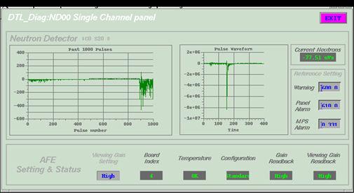
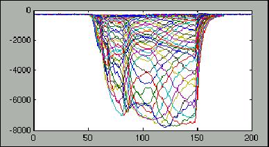
70 Example Measurements Position, phase Current (toroids) Loss (ion chambers) emittance Current (MEBT beam stop) Current (D-plate beam stop) Current (DTL Faraday cup) Loss (neutron) Profile (wires) Halo 72 Bunch shape

71 Laser-Stripping Injection Proof-of-Principle Experiment We are receiving funds from the Lab Directors R&D (LDRD) program to perform a proof-ofprinciple experiment to test a scheme for laser-stripping injection First experimental tests were carried out in early December We observed >50% doublestripping efficiency in first attempt in a one-hour run Further R&D will continue, with the goal of developing a realistic laser-based scheme Flipped-sign notch on BCM indicates protons Laser Beam High-field Dipole Magnet H- H0 Step 1: Lorentz Stripping H- H0 + e- 73 H0* Step 2: Laser Excitation H0 (n=1) + H0* (n=3) High-field Dipole Magnet proton Step 3: Lorentz Stripping H0* p + e-

72 Now he should leave Thanks for all the congratulations!!!! 74
Oak Ridge Spallation Neutron Source Proton Power Upgrade Project and Second Target Station Project
 Oak Ridge Spallation Neutron Source Proton Power Upgrade Project and Second Target Station Project Workshop on the future and next generation capabilities of accelerator driven neutron and muon sources
Status of the SNS Linac: An Overview N. Holtkamp for the SNS Collaboration ORNL, Oak Ridge, TN 37830, USA
 Lübeck, August 20, 2004 Status of the SNS Linac: An Overview N. Holtkamp for the SNS Collaboration ORNL, Oak Ridge, TN 37830, USA SNS is the Forefront Facility for Future High Beam Power Accelerators Highest
Linac 4 Instrumentation K.Hanke CERN
 Linac 4 Instrumentation K.Hanke CERN CERN Linac 4 PS2 (2016?) SPL (2015?) Linac4 (2012) Linac4 will first inject into the PSB and then can be the first element of a new LHC injector chain. It will increase
Workshop on Accelerator Operations August 6-10, 2012 Glen D. Johns Accelerator Operations Manager
 HWDB: Operations at the Spallation Neutron Source Workshop on Accelerator Operations August 6-10, 2012 Glen D. Johns Accelerator Operations Manager Outline Facility overview Organization Shift schedule
Commissioning of Accelerators. Dr. Marc Munoz (with the help of R. Miyamoto, C. Plostinar and M. Eshraqi)
") Commissioning of Accelerators Dr. Marc Munoz (with the help of R. Miyamoto, C. Plostinar and M. Eshraqi) www.europeanspallationsource.se 6 July, 2017 Contents General points Definition of Commissioning
Commissioning of Accelerators Dr. Marc Munoz (with the help of R. Miyamoto, C. Plostinar and M. Eshraqi) www.europeanspallationsource.se 6 July, 2017 Contents General points Definition of Commissioning
Experience with the Cornell ERL Injector SRF Cryomodule during High Beam Current Operation
 Experience with the Cornell ERL Injector SRF Cryomodule during High Beam Current Operation Matthias Liepe Assistant Professor of Physics Cornell University Experience with the Cornell ERL Injector SRF
A Fifteen Year Perspective on the Design and Performance of the SNS Accelerator
 A Fifteen Year Perspective on the Design and Performance of the SNS Accelerator S. Cousineau (On behalf of the SNS project) HB2016, Sweden July 04, 2016 ORNL is managed by UT-Battelle for the US Department
The ESS Accelerator. For Norwegian Industry and Research. Oslo, 24 Sept Håkan Danared Deputy Head Accelerator Division Group Leader Beam Physics
 The ESS Accelerator For Norwegian Industry and Research Oslo, 24 Sept 2013 Håkan Danared Deputy Head Accelerator Division Group Leader Beam Physics The Hadron Intensity Frontier Courtesy of M. Seidel (PSI)
Beam Loss Detection for MPS at FRIB
 Beam Loss Detection for MPS at FRIB Zhengzheng Liu Beam Diagnostics Physicist This material is based upon work supported by the U.S. Department of Energy Office of Science under Cooperative Agreement DE-SC0000661.
OPERATIONAL EXPERIENCE AT J-PARC
 OPERATIONAL EXPERIENCE AT J-PARC Hideaki Hotchi, ) for J-PARC commissioning team ), 2), ) Japan Atomic Energy Agency (JAEA), Tokai, Naka, Ibaraki, 39-95 Japan, 2) High Energy Accelerator Research Organization
The PEFP 20-MeV Proton Linear Accelerator
 Journal of the Korean Physical Society, Vol. 52, No. 3, March 2008, pp. 721726 Review Articles The PEFP 20-MeV Proton Linear Accelerator Y. S. Cho, H. J. Kwon, J. H. Jang, H. S. Kim, K. T. Seol, D. I.
Upgrading LHC Luminosity
 1 Upgrading LHC Luminosity 2 Luminosity (cm -2 s -1 ) Present (2011) ~2 x10 33 Beam intensity @ injection (*) Nominal (2015?) 1 x 10 34 1.1 x10 11 Upgraded (2021?) ~5 x10 34 ~2.4 x10 11 (*) protons per
SNS Target Imaging and Related Developments
 SNS Target Imaging and Related Developments Tom Shea (ORNL) ESS Seminar Lund, Sweden January 28, 2011 T. J. Shea, T. McManamy, G. Bancke, W. Blokland, A. Brunson, M. Dayton, R. Fiorito, K. C. Goetz, J.
ESS: The Machine. Bucharest, 24 April Håkan Danared Deputy Head Accelerator Division. H. Danared Industry & Partner Days Bucharest Page 1
 ESS: The Machine Bucharest, 24 April 2014 Håkan Danared Deputy Head Accelerator Division H. Danared Industry & Partner Days Bucharest Page 1 2025 ESS construction complete 2009 Decision: ESS will be built
DESIGN OF 1.2-GEV SCL AS NEW INJECTOR FOR THE BNL AGS*
 DESIGN OF 1.2-GEV SCL AS NEW INJECTOR FOR THE BNL AGS* A. G. Ruggiero, J. Alessi, M. Harrison, M. Iarocci, T. Nehring, D. Raparia, T. Roser, J. Tuozzolo, W. Weng. Brookhaven National Laboratory, PO Box
The Construction Status of CSNS Linac
 The Construction Status of CSNS Linac Sheng Wang Dongguan branch, Institute of High Energy Physics, CAS Sep.2, 2014, Geneva Outline The introduction to CSNS accelerators The commissoning of ion source
3 cerl. 3-1 cerl Overview. 3-2 High-brightness DC Photocathode Gun and Gun Test Beamline
 3 cerl 3-1 cerl Overview As described before, the aim of the cerl in the R&D program includes the development of critical components for the ERL, as well as the construction of a test accelerator. The
2 Work Package and Work Unit descriptions. 2.8 WP8: RF Systems (R. Ruber, Uppsala)
") 2 Work Package and Work Unit descriptions 2.8 WP8: RF Systems (R. Ruber, Uppsala) The RF systems work package (WP) addresses the design and development of the RF power generation, control and distribution
2 Work Package and Work Unit descriptions 2.8 WP8: RF Systems (R. Ruber, Uppsala) The RF systems work package (WP) addresses the design and development of the RF power generation, control and distribution
30 GHz Power Production / Beam Line
 30 GHz Power Production / Beam Line Motivation & Requirements Layout Power mode operation vs. nominal parameters Beam optics Achieved performance Problems Beam phase switch for 30 GHz pulse compression
Proton Engineering Frontier Project
 Proton Engineering Frontier Project OECD Nuclear Energy Agency Fifth International Workshop on the Utilisation and Reliability of High Power Proton Accelerators (HPPA5) (6-9 May 2007, Mol, Belgium) Yong-Sub
COMMISSIONING SCENARIOS FOR THE J-PARC ACCELERATOR COMPLEX
 COMMISSIONING SCENARIOS FOR THE J-PARC ACCELERATOR COMPLEX T. Koseki, M. Ikegami, M. Tomizawa, Accelerator Laboratory, KEK, Tsukuba, Japan F. Noda, JAEA, Tokai, Japan Abstract The J-PARC (Japan Proton
PEP II Design Outline
 PEP II Design Outline Balša Terzić Jefferson Lab Collider Review Retreat, February 24, 2010 Outline General Information Parameter list (and evolution), initial design, upgrades Collider Ring Layout, insertions,
PRESENT STATUS OF J-PARC
 PRESENT STATUS OF J-PARC # F. Naito, KEK, Tsukuba, Japan Abstract Japan Proton Accelerator Research Complex (J-PARC) is the scientific facility with the high-intensity proton accelerator aiming to realize
Diamond RF Status (RF Activities at Daresbury) Mike Dykes
 Mike Dykes") Diamond RF Status (RF Activities at Daresbury) Mike Dykes ASTeC What is it? What does it do? Diamond Status Linac Booster RF Storage Ring RF Summary Content ASTeC ASTeC was formed in 2001 as a centre of
Diamond RF Status (RF Activities at Daresbury) Mike Dykes ASTeC What is it? What does it do? Diamond Status Linac Booster RF Storage Ring RF Summary Content ASTeC ASTeC was formed in 2001 as a centre of
Design of the linear accelerator for the MYRRHA project
 MYRRHA Multipurpose hybrid Research Reactor for High-tech Applications Design of the linear accelerator for the MYRRHA project Roberto Salemme ADT - Outline What is MYRRHA? MYRRHA accelerator: requirements
The Elettra Storage Ring and Top-Up Operation
 The Elettra Storage Ring and Top-Up Operation Emanuel Karantzoulis Past and Present Configurations 1994-2007 From 2008 5000 hours /year to the users 2010: Operations transition year Decay mode, 2 GeV (340mA)
Digital BPMs and Orbit Feedback Systems
 Digital BPMs and Orbit Feedback Systems, M. Böge, M. Dehler, B. Keil, P. Pollet, V. Schlott Outline stability requirements at SLS storage ring digital beam position monitors (DBPM) SLS global fast orbit
RF plans for ESS. Morten Jensen. ESLS-RF 2013 Berlin
 RF plans for ESS Morten Jensen ESLS-RF 2013 Berlin Overview The European Spallation Source (ESS) will house the most powerful proton linac ever built. The average beam power will be 5 MW which is five
Detailed Design Report
 Detailed Design Report Chapter 4 MAX IV Injector 4.6. Acceleration MAX IV Facility CHAPTER 4.6. ACCELERATION 1(10) 4.6. Acceleration 4.6. Acceleration...2 4.6.1. RF Units... 2 4.6.2. Accelerator Units...
Preparations for Installation, Testing and Commissioning based on Experience at CERN, SNS and Siemens
 Preparations for Installation, Testing and Commissioning based on Experience at CERN, SNS and Siemens Eugène Tanke FRIB / MSU ESS Seminar, Lund, 6 March 2013 Outline Project Goal for the Accelerator Path
HIGH POWER BEAM DUMP AND TARGET / ACCELERATOR INTERFACE PROCEDURES *
 HIGH POWER BEAM DUMP AND TARGET / ACCELERATOR INTERFACE PROCEDURES * J. Galambos, W. Blokland, D. Brown, C. Peters, M. Plum, Spallation Neutron Source, ORNL, Oak Ridge, TN 37831, U.S.A. Abstract Satisfying
SPEAR 3: Operations Update and Impact of Top-Off Injection
 SPEAR 3: Operations Update and Impact of Top-Off Injection R. Hettel for the SSRL ASD 2005 SSRL Users Meeting October 18, 2005 SPEAR 3 Operations Update and Development Plans Highlights of 2005 SPEAR 3
High Brightness Injector Development and ERL Planning at Cornell. Charlie Sinclair Cornell University Laboratory for Elementary-Particle Physics
 High Brightness Injector Development and ERL Planning at Cornell Charlie Sinclair Cornell University Laboratory for Elementary-Particle Physics June 22, 2006 JLab CASA Seminar 2 Background During 2000-2001,
RF considerations for SwissFEL
 RF considerations for H. Fitze in behalf of the PSI RF group Workshop on Compact X-Ray Free Electron Lasers 19.-21. July 2010, Shanghai Agenda Introduction RF-Gun Development C-band development Summary
Status of SOLARIS Arkadiusz Kisiel
 Status of SOLARIS Arkadiusz Kisiel Solaris National Synchrotron Light Source Jagiellonian University Czerwone Maki 98 30-392 Kraków www.synchrotron.uj.edu.pl Arkadiusz.Kisiel@uj.edu.pl On behalf of SOLARIS
5 Project Costs and Schedule
 93 5 Project Costs and Schedule 5.1 Overview The cost evaluation for the integrated version of the XFEL with 30 experiments and 35 GeV beam energy as described in the TDR-2001 yielded 673 million EUR for
4.4 Injector Linear Accelerator
 4.4 Injector Linear Accelerator 100 MeV S-band linear accelerator based on the components already built for the S-Band Linear Collider Test Facility at DESY [1, 2] will be used as an injector for the CANDLE
Upgrade of CEBAF to 12 GeV
 Upgrade of CEBAF to 12 GeV Leigh Harwood (for 12 GeV Accelerator team) Page 1 Outline Background High-level description Schedule Sub-system descriptions and status Summary Page 2 CEBAF Science Mission
The Beam Test Facility at the SNS
 The Beam Test Facility at the SNS R.F. Welton, A. Aleksandrov, B.X. Han, Y.W. Kang, M.M. Middendorf, S.N. Murray, M. Piller, T.R. Pennisi, V. Peplov, R. Saethre, M. Santana, C. Stinson, M.P. Stockli and
Summary of the 1 st Beam Line Review Meeting Injector ( )
") Summary of the 1 st Beam Line Review Meeting Injector (23.10.2006) 15.11.2006 Review the status of: beam dynamics understanding and simulations completeness of beam line description conceptual design of
Summary of the 1 st Beam Line Review Meeting Injector (23.10.2006) 15.11.2006 Review the status of: beam dynamics understanding and simulations completeness of beam line description conceptual design of
New Results on the Electron Cloud at the Los Alamos PSR
 New Results on the Electron Cloud at the Los Alamos PSR Robert Macek, LANL, 4/15/02 Co-authors: A. Browman, D. Fitzgerald, R. McCrady, T. Spickermann, & T. S. Wang - LANL For more information see the website
SUMMARY OF THE ILC R&D AND DESIGN
 SUMMARY OF THE ILC R&D AND DESIGN B. C. Barish, California Institute of Technology, USA Abstract The International Linear Collider (ILC) is a linear electron-positron collider based on 1.3 GHz superconducting
CLIC Feasibility Demonstration at CTF3
 CLIC Feasibility Demonstration at CTF3 Roger Ruber Uppsala University, Sweden, for the CLIC/CTF3 Collaboration http://cern.ch/clic-study LINAC 10 MO303 13 Sep 2010 The Key to CLIC Efficiency NC Linac for
P. Emma, et al. LCLS Operations Lectures
 P. Emma, et al. LCLS Operations Lectures LCLS 1 LCLS Accelerator Schematic 6 MeV 135 MeV 250 MeV σ z 0.83 mm σ z 0.83 mm σ z 0.19 mm σ δ 0.05 % σ δ 0.10 % σ δ 1.6 % Linac-0 L =6 m rf gun L0-a,b Linac-1
LHC Beam Instrumentation Further Discussion
 LHC Beam Instrumentation Further Discussion LHC Machine Advisory Committee 9 th December 2005 Rhodri Jones (CERN AB/BDI) Possible Discussion Topics Open Questions Tune measurement base band tune & 50Hz
SNS TR0001-R00. Conceptual Design Report for the Spallation Neutron Source Power Upgrade MIE Project
 SNS-300000000-TR0001-R00 Conceptual Design Report for the Spallation Neutron Source Power Upgrade MIE Project This report was prepared as an account of work sponsored by an agency of the United States
A HIGH-POWER SUPERCONDUCTING H - LINAC (SPL) AT CERN
 AT CERN") A HIGH-POWER SUPERCONDUCTING H - LINAC (SPL) AT CERN E. Chiaveri, CERN, Geneva, Switzerland Abstract The conceptual design of a superconducting H - linear accelerator at CERN for a beam energy of 2.2 GeV
A HIGH-POWER SUPERCONDUCTING H - LINAC (SPL) AT CERN E. Chiaveri, CERN, Geneva, Switzerland Abstract The conceptual design of a superconducting H - linear accelerator at CERN for a beam energy of 2.2 GeV
RF Upgrades & Experience At JLab. Rick Nelson
 RF Upgrades & Experience At JLab Rick Nelson Outline Background: CEBAF / Jefferson Lab History, upgrade requirements & decisions Progress & problems along the way Present status Future directions & concerns
IOT OPERATIONAL EXPERIENCE ON ALICE AND EMMA AT DARESBURY LABORATORY
 IOT OPERATIONAL EXPERIENCE ON ALICE AND EMMA AT DARESBURY LABORATORY A. Wheelhouse ASTeC, STFC Daresbury Laboratory ESLS XVIII Workshop, ELLETRA 25 th 26 th November 2010 Contents Brief Description ALICE
Status of SOLARIS. Paweł Borowiec On behalf of Solaris Team
 Status of SOLARIS Paweł Borowiec On behalf of Solaris Team e-mail: pawel.borowiec@uj.edu.pl XX ESLS-RF Meeting, Villingen 16-17.11.2016 Outline 1. Timeline 2. Injector 3. Storage ring 16-17.11.2016 XX
Status and Plans for PEP-II
 Status and Plans for PEP-II John Seeman SLAC Particle and Particle-Astrophysics DOE HEPAP P5 Review April 21, 2006 Topics Luminosity records for PEP-II in October 2005 Fall shut-down upgrades Run 5b turn
Jefferson Lab Experience with Beam Halo, Beam Loss, etc.
 Jefferson Lab Experience with Beam Halo, Beam Loss, etc. Pavel Evtushenko with a lot of input from many experienced colleagues Steve Benson, Dave Douglas, Kevin Jordan, Carlos Hernandez-Garcia, Dan Sexton,
CEBAF Accelerator Update. Michael Tiefenback CASA Accelerator Physics Experimental Liaison June 14, 2017
 CEBAF Accelerator Update Michael Tiefenback CASA Accelerator Physics Experimental Liaison June 14, 2017 CLAS12 Collaboration Meeting, June 13-16, 2017 1 Accelerator Division Leadership On April 30 Andrew
Status of BESSY II and berlinpro. Wolfgang Anders. Helmholtz-Zentrum Berlin for Materials and Energy (HZB) 20th ESLS-RF Meeting
 20th ESLS-RF Meeting") Status of BESSY II and berlinpro Wolfgang Anders Helmholtz-Zentrum Berlin for Materials and Energy (HZB) 20th ESLS-RF Meeting 16.-17.11.2016 at PSI Outline BESSY II Problems with circulators Landau cavity
Status of BESSY II and berlinpro Wolfgang Anders Helmholtz-Zentrum Berlin for Materials and Energy (HZB) 20th ESLS-RF Meeting 16.-17.11.2016 at PSI Outline BESSY II Problems with circulators Landau cavity
HIGH-INTENSITY PROTON BEAMS AT CERN AND THE SPL STUDY
 HIGH-INTENSITY PROTON BEAMS AT CERN AND THE STUDY E. Métral, M. Benedikt, K. Cornelis, R. Garoby, K. Hanke, A. Lombardi, C. Rossi, F. Ruggiero, M. Vretenar, CERN, Geneva, Switzerland Abstract The construction
Basic rules for the design of RF Controls in High Intensity Proton Linacs. Particularities of proton linacs wrt electron linacs
 Basic rules Basic rules for the design of RF Controls in High Intensity Proton Linacs Particularities of proton linacs wrt electron linacs Non-zero synchronous phase needs reactive beam-loading compensation
EPJ Web of Conferences 95,
 EPJ Web of Conferences 95, 04012 (2015) DOI: 10.1051/ epjconf/ 20159504012 C Owned by the authors, published by EDP Sciences, 2015 The ELENA (Extra Low Energy Antiproton) project is a small size (30.4
The FAIR plinac RF Systems
 The FAIR plinac RF Systems Libera Workshop Sep. 2011 Gerald Schreiber Gerald Schreiber, GSI RF Department 2 (1) Overview GSI / FAIR (2) FAIR Proton Linear Accelerator "plinac" (3) plinac RF Systems (4)
2008 JINST 3 S LHC Machine THE CERN LARGE HADRON COLLIDER: ACCELERATOR AND EXPERIMENTS. Lyndon Evans 1 and Philip Bryant (editors) 2
 2") PUBLISHED BY INSTITUTE OF PHYSICS PUBLISHING AND SISSA RECEIVED: January 14, 2007 REVISED: June 3, 2008 ACCEPTED: June 23, 2008 PUBLISHED: August 14, 2008 THE CERN LARGE HADRON COLLIDER: ACCELERATOR AND
PUBLISHED BY INSTITUTE OF PHYSICS PUBLISHING AND SISSA RECEIVED: January 14, 2007 REVISED: June 3, 2008 ACCEPTED: June 23, 2008 PUBLISHED: August 14, 2008 THE CERN LARGE HADRON COLLIDER: ACCELERATOR AND
A HIGH POWER LONG PULSE HIGH EFFICIENCY MULTI BEAM KLYSTRON
 A HIGH POWER LONG PULSE HIGH EFFICIENCY MULTI BEAM KLYSTRON A.Beunas and G. Faillon Thales Electron Devices, Vélizy, France S. Choroba DESY, Hamburg, Germany Abstract THALES ELECTRON DEVICES has developed
Current status of XFEL/SPring-8 project and SCSS test accelerator
 Current status of XFEL/SPring-8 project and SCSS test accelerator Takahiro Inagaki for XFEL project in SPring-8 inagaki@spring8.or.jp Outline (1) Introduction (2) Key technology for compactness (3) Key
Commissioning the TAMUTRAP RFQ cooler/buncher. E. Bennett, R. Burch, B. Fenker, M. Mehlman, D. Melconian, and P.D. Shidling
 Commissioning the TAMUTRAP RFQ cooler/buncher E. Bennett, R. Burch, B. Fenker, M. Mehlman, D. Melconian, and P.D. Shidling In order to efficiently load ions into a Penning trap, the ion beam should be
Low Level RF for PIP-II. Jonathan Edelen LLRF 2017 Workshop (Barcelona) 16 Oct 2017
 16 Oct 2017") Low Level RF for PIP-II Jonathan Edelen LLRF 2017 Workshop (Barcelona) 16 Oct 2017 PIP-II LLRF Team Fermilab Brian Chase, Edward Cullerton, Joshua Einstein, Jeremiah Holzbauer, Dan Klepec, Yuriy Pischalnikov,
Low Level RF for PIP-II Jonathan Edelen LLRF 2017 Workshop (Barcelona) 16 Oct 2017 PIP-II LLRF Team Fermilab Brian Chase, Edward Cullerton, Joshua Einstein, Jeremiah Holzbauer, Dan Klepec, Yuriy Pischalnikov,
North Damping Ring RF
 North Damping Ring RF North Damping Ring RF Outline Overview High Power RF HVPS Klystron & Klystron EPICS controls Cavities & Cavity Feedback SCP diagnostics & displays FACET-specific LLRF LLRF distribution
Welcome and FRIB Project Status. FRIB Highlights and Plan Ahead
 Welcome and FRIB Project Status Thomas Glasmacher Project Manager This material is based upon work supported by the U.S. Department of Energy Office of Science under Cooperative Agreement DE-SC0000661.
Week 0: PPS Certification and Processing. Mon Feb 11 Tue Feb 12 Wed Feb 13 Thu Feb 14 Fri Feb 15 Sat Feb 16 Sun Feb 17
 Week 0: PPS Certification and Processing Mon Feb 11 Tue Feb 12 Wed Feb 13 Thu Feb 14 Fri Feb 15 Sat Feb 16 Sun Feb 17 Work in tunnel Work in tunnel PPS Certification PPS Certification PPS Certification
Present Status and Future Upgrade of KEKB Injector Linac
 Present Status and Future Upgrade of KEKB Injector Linac Kazuro Furukawa, for e /e + Linac Group Present Status Upgrade in the Near Future R&D towards SuperKEKB 1 Machine Features Present Status and Future
STATUS OF THE SWISSFEL C-BAND LINEAR ACCELERATOR
 Proceedings of FEL213, New York, NY, USA STATUS OF THE SWISSFEL C-BAND LINEAR ACCELERATOR F. Loehl, J. Alex, H. Blumer, M. Bopp, H. Braun, A. Citterio, U. Ellenberger, H. Fitze, H. Joehri, T. Kleeb, L.
PEP II STATUS AND PLANS *
 PEP II STATUS AND PLANS * John T. Seeman + Stanford Linear Accelerator Center, Stanford University, Stanford, CA 94309 USA The PEP II B-Factory 1 project is an e + e - colliding beam storage ring complex
WG2 Group Summary. Chris Adolphsen Terry Garvey Hitoshi Hayano
 WG2 Group Summary Chris Adolphsen Terry Garvey Hitoshi Hayano Linac Options Fest On Thursday afternoon, various experts summarized the linac baseline options. Although hard choices have yet to be made,
A New High Intensity Proton Source. The SCRF Proton Driver. (and more!) at Fermilab. July 15, Bill Foster SRF2005
 at Fermilab. July 15, Bill Foster SRF2005") The SCRF Proton Driver A New High Intensity Proton Source (and more!) at Fermilab Bill Foster SRF2005 July 15, 2005 Outline The Concept Fermilab Strategic Context Proton Driver SRF Linac Design Ferrite
The SCRF Proton Driver A New High Intensity Proton Source (and more!) at Fermilab Bill Foster SRF2005 July 15, 2005 Outline The Concept Fermilab Strategic Context Proton Driver SRF Linac Design Ferrite
ESS Linac WP8 Radio Frequency Systems and Test Facilities
 ESS Linac WP8 Radio Frequency Systems and Test Facilities ESS/SPL Collaboration Meeting Lund, 29 June 2010 Roger Ruber (Uppsala University) for the ESS Linac RF Team ESS Linac WP8: RF Systems Outline Work
Particle Beam Production - A Synchrotron-Based System - Prof. Dr. Thomas Haberer Scientific-technical Director Heidelberg Iontherapy Center
 Particle Beam Production - A Synchrotron-Based System - Prof. Dr. Thomas Haberer Scientific-technical Director Heidelberg Iontherapy Center Outline Situation/Rationale Requirements Synchrotron choice Functions
FINAL DESIGN OF ILC RTML EXTRACTION LINE FOR SINGLE STAGE BUNCH COMPRESSOR
 BNL-94942-2011-CP FINAL DESIGN OF ILC RTML EXTRACTION LINE FOR SINGLE STAGE BUNCH COMPRESSOR S. Sletskiy and N. Solyak Presented at the 2011 Particle Accelerator Conference (PAC 11) New York, NY March
LIGHT PROTON THERAPY PROJECT
 17 th of MAY 2018 LIGHT PROTON THERAPY PROJECT Yevgeniy Ivanisenko on behalf of ADAM team FORM-01040-A AVO-ADAM Advanced Oncotherapy (AVO) is a public company ADAM is R&D center of AVO ~ 100 employees
Status of RF Power and Acceleration of the MAX IV - LINAC
 Status of RF Power and Acceleration of the MAX IV - LINAC Dionis Kumbaro ESLS RF Workshop 2015 MAX IV Laboratory A National Laboratory for synchrotron radiation at Lunds University 1981 MAX-lab is formed
LEP OPERATION AND PERFORMANCE WITH ELECTRON-POSITRON COLLISIONS AT 209 GEV
 LEP OPERATION AND PERFORMANCE WITH ELECTRON-POSITRON COLLISIONS AT 29 GEV R. W. Aßmann, CERN, Geneva, Switzerland Abstract The Large Electron-Positron Collider (LEP) at CERN completed its operation in
Report from the 3 rd Meeting of the Accelerator Technical Advisory Committee for the Japan Proton Accelerator Research Complex (J-PARC)
") Report from the 3 rd Meeting of the Accelerator Technical Advisory Committee for the Japan Proton Accelerator Research Complex (J-PARC) March 5-6, 2004 JAERI Tokai, Japan Table of Contents Page Executive
Report from the 3 rd Meeting of the Accelerator Technical Advisory Committee for the Japan Proton Accelerator Research Complex (J-PARC) March 5-6, 2004 JAERI Tokai, Japan Table of Contents Page Executive
Progress of Beam Instrumentation in J-PARC Linac
 IBIC2012 International Beam Instrumentation Conference Tsukuba, Ibaraki, JAPAN, 1 st to 4 th, Oct. 2011 Progress of Beam Instrumentation in J-PARC Linac Akihiko MIURA with the Beam Monitor Group in J-PARC
The European Spallation Source
 The European Spallation Source Roger Ruber Uppsala University NIKHEF industriemiddag 21 september 2011 The European Spallation Source Roger Ruber - The European Spallation Source NIKHEF, 21-Sep-2011 page
INFN School on Electron Accelerators. RF Power Sources and Distribution
 INFN School on Electron Accelerators 12-14 September 2007, INFN Sezione di Pisa Lecture 7b RF Power Sources and Distribution Carlo Pagani University of Milano INFN Milano-LASA & GDE The ILC Double Tunnel
New Filling Pattern for SLS-FEMTO
 SLS-TME-TA-2009-0317 July 14, 2009 New Filling Pattern for SLS-FEMTO Natalia Prado de Abreu, Paul Beaud, Gerhard Ingold and Andreas Streun Paul Scherrer Institut, CH-5232 Villigen PSI, Switzerland A new
ESS Linac WP8 Radio Frequency Systems and Test Facilities
 ESS Linac WP8 Radio Frequency Systems and Test Facilities ESS TAC Lund, 8 July 2010 Roger Ruber (Uppsala University) for the ESS Linac RF Team Outline Work Package description Objectives Organization Technical
Status of CTF3. G.Geschonke CERN, AB
 Status of CTF3 G.Geschonke CERN, AB CTF3 layout CTF3 - Test of Drive Beam Generation, Acceleration & RF Multiplication by a factor 10 Drive Beam Injector ~ 50 m 3.5 A - 2100 b of 2.33 nc 150 MeV - 1.4
PoS(EPS-HEP2015)525. The RF system for FCC-ee. A. Butterworth CERN 1211 Geneva 23, Switzerland
525. The RF system for FCC-ee. A. Butterworth CERN 1211 Geneva 23, Switzerland") CERN 1211 Geneva 23, Switzerland E-mail: andrew.butterworth@cern.ch O. Brunner CERN 1211 Geneva 23, Switzerland E-mail: olivier.brunner@cern.ch R. Calaga CERN 1211 Geneva 23, Switzerland E-mail: rama.calaga@cern.ch
CERN 1211 Geneva 23, Switzerland E-mail: andrew.butterworth@cern.ch O. Brunner CERN 1211 Geneva 23, Switzerland E-mail: olivier.brunner@cern.ch R. Calaga CERN 1211 Geneva 23, Switzerland E-mail: rama.calaga@cern.ch
Design Studies For The LCLS 120 Hz RF Gun Injector
 BNL-67922 Informal Report LCLS-TN-01-3 Design Studies For The LCLS 120 Hz RF Gun Injector X.J. Wang, M. Babzien, I. Ben-Zvi, X.Y. Chang, S. Pjerov, and M. Woodle National Synchrotron Light Source Brookhaven
Characterizing Transverse Beam Dynamics at the APS Storage Ring Using a Dual-Sweep Streak Camera
 Characterizing Transverse Beam Dynamics at the APS Storage Ring Using a Dual-Sweep Streak Camera Bingxin Yang, Alex H. Lumpkin, Katherine Harkay, Louis Emery, Michael Borland, and Frank Lenkszus Advanced
The SPL at CERN. slhc. 1. Introduction 2. Description. 3. Status of the SPL study. - Stage 1: Linac4 - Stage 2: LP-SPL - Potential further stages
 The SPL at CERN 1. Introduction 2. Description - Stage 1: Linac4 - Stage 2: LP-SPL - Potential further stages 3. Status of the SPL study slhc Roa Garoby for the SPL team 1. Introduction Motivation for
Pulsed Klystrons for Next Generation Neutron Sources Edward L. Eisen - CPI, Inc. Palo Alto, CA, USA
 Pulsed Klystrons for Next Generation Neutron Sources Edward L. Eisen - CPI, Inc. Palo Alto, CA, USA Abstract The U.S. Department of Energy (DOE) Office of Science has funded the construction of a new accelerator-based
RF Power Generation II
 RF Power Generation II Klystrons, Magnetrons and Gyrotrons Professor R.G. Carter Engineering Department, Lancaster University, U.K. and The Cockcroft Institute of Accelerator Science and Technology Scope
TITLE PAGE. Title of paper: PUSH-PULL FEL, A NEW ERL CONCEPT Author: Andrew Hutton. Author Affiliation: Jefferson Lab. Requested Proceedings:
 TITLE PAGE Title of paper: PUSH-PULL FEL, A NEW ERL CONCEPT Author: Andrew Hutton Author Affiliation: Jefferson Lab Requested Proceedings: Unique Session ID: Classification Codes: Keywords: Energy Recovery,
DELIVERY RECORD. Location: Ibaraki, Japan
 DELIVERY RECORD Client: Japan Atomic Energy Agency (JAEA) High Energy Accelerator Research Organization (KEK) Facility: J-PARC (Japan Proton Accelerator Research Complex) Location: Ibaraki, Japan 1 October
Hall-B Beamline Commissioning Plan for CLAS12
 Hall-B Beamline Commissioning Plan for CLAS12 Version 1.5 S. Stepanyan December 19, 2017 1 Introduction The beamline for CLAS12 utilizes the existing Hall-B beamline setup with a few modifications and
Accelerator Instrumentation RD. Monday, July 14, 2003 Marc Ross
 Monday, Marc Ross Linear Collider RD Most RD funds address the most serious cost driver energy The most serious impact of the late technology choice is the failure to adequately address luminosity RD issues
THE NEXT LINEAR COLLIDER TEST ACCELERATOR: STATUS AND RESULTS * Abstract
 SLAC PUB 7246 June 996 THE NEXT LINEAR COLLIDER TEST ACCELERATOR: STATUS AND RESULTS * Ronald D. Ruth, SLAC, Stanford, CA, USA Abstract At SLAC, we are pursuing the design of a Next Linear Collider (NLC)
Next Linear Collider. The 8-Pack Project. 8-Pack Project. Four 50 MW XL4 X-band klystrons installed on the 8-Pack
 The Four 50 MW XL4 X-band klystrons installed on the 8-Pack The Demonstrate an NLC power source Two Phases: 8-Pack Phase-1 (current): Multi-moded SLED II power compression Produce NLC baseline power: 475
!"!3
 Abstract A single-mode 500 MHz superconducting cavity cryomodule has been developed at Cornell for the electronpositron collider/synchrotron light source CESR. The Cornell B-cell cavity belongs to the
Status of Elettra, top-up and other upgrades
 Status of Elettra, top-up and other upgrades Emanuel Karantzoulis ELETTRA / Trieste, Italy / 2010 November 25-26 Past and Present Configurations 1994-2007 From 2008 No full energy injection Full energy
ILC-LNF TECHNICAL NOTE
 IL-LNF EHNIAL NOE Divisione Acceleratori Frascati, July 4, 2006 Note: IL-LNF-001 RF SYSEM FOR HE IL DAMPING RINGS R. Boni, INFN-LNF, Frascati, Italy G. avallari, ERN, Geneva, Switzerland Introduction For
High Rep Rate Guns: FZD Superconducting RF Photogun
 High Rep Rate Guns: FZD Superconducting RF Photogun J. Teichert, A. Arnold, H. Büttig, D. Janssen, M. Justus, U. Lehnert, P. Michel, K. Moeller, P. Murcek, Ch. Schneider, R. Schurig, G. Staats, F. Staufenbiel,