CLIC Status. D. Schulte for the CLIC collaboration
|
|
|
- William Morrison
- 5 years ago
- Views:
Transcription
1 CLIC Status D. Schulte for the CLIC collaboration 1


2 Timeline From Steinar 2


3 Conclusion of the Accelerator CDR Studies Main linac gradient Ongoing test close to or on target Uncertainty from beam loading being tested Drive beam scheme Generation tested, used to accelerate test beam above specifications, deceleration as expected Improvements on operation, reliability, losses, more deceleration studies underway TD24 baseline: Unloaded 106 MV/m Expected with beam loading 0-16% less CLIC Nominal, unloaded CLIC Nominal, loaded Luminosity Damping ring like an ambitious light source, no show stopper Alignment system principle demonstrated Stabilisation system developed, benchmarked, better system in pipeline Simulations on or close to the target Operation & Machine Protection Start-up sequence and low energy operation defined Most critical failure studied and first reliability studies Implementation Consistent staged implementation scenario defined Schedules, cost and power developed and presented Site and CE studies documented 3 3

4 Achieved Gradient for CLIC Tests at KEK and SLAC Measurements scaled according to Simple early design to get started More efficient fully optimised structure No damping waveguides T18 T24 Unloaded 106MV/m With loading 0-16% less Damping waveguides TD18 TD24 = CLIC goal RF Team 4


5 NEXTEF at KEK Klystron-based Test Stands for CLIC ASTA at SLAC? XBox1 at CERN operational with SLAC klystron XBox2 at CERN, industrial klystron should be ready this year 5
 Beam Test stand in CTF3 dog-leg to test")

6 Beam Loading Test Facility Unloaded RF Dog-leg Average gradient 100 MV/m 50 mm circular waveguide Loaded (CLIC) Beam Test stand in CTF3 dog-leg to test gradient with beam loading Structure can be power with klystron Can send drive beam through structure System is commissioned Conditioned structure to come in summer 6


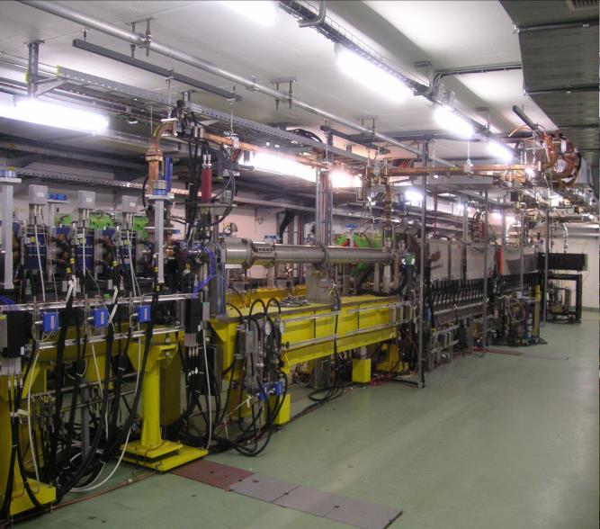
7 CLIC Test Facility (CTF3) Operation of isochronous lines and rings 4 A, 1.4us 120 MeV High current, full beam-loading operation 30 A, 140 ns 120 MeV Beam recombination and current multiplication by RF deflectors Bunch phase coding 30 A, 140 ns 60 MeV 12 GHz power generation by drive beam deceleration High-gradient twobeam acceleration 7 7
 Good understanding of the optics Goal is to reach 40%")
8 Recent CTF3 Results Operation with 8 times combination now routine New feedbacks added to improve phase stability Goal is to achieve e x = e y 150 μm also for factor 8, currently e x =550μm due to orbit error Charge stability s Q 10-3 for factor 8 Deceleration increased from 30% to 35% Decelerator BPM prototype tested (stripline, LAPP) Good understanding of the optics Goal is to reach 40% deceleration More results and more details in Roberto s talk CTF3 Team 8

 in summer First tests in autumn CTF3 Team INFN")
9 Structure with wakemonitor installed in TBTS Resolution is very good Recent CTF3 Results CEA IRFU - Saclay Feedforward to correct drive beam phase Phase monitors successfully tested Goal: Install kickers and amplifiers (FONT5) in summer First tests in autumn CTF3 Team INFN Frascati JAI/Oxford 9
10 CLIC Drive Beam Front End Hardware Prototypes and Plans Task 2013 Modulator-klystron, 1 GHz, MW prepare gun test testing with HV Gun test area area 500 MHz ready for first tests modulator testing Gun design Prototype, first tests gun tests SHB Buncher Gun fabrication testing low power testing high power 500 MHz power ~ 140 source kev specifications purchase needed for test Diagnostics 1 GHz structure specs, mech. design construction low power test high power test Diagnostis design design tests in gun area? SHB LLRF specs 1 fabrication+test Acc. Structures ready for klystron test 1 GHz klystrons tender, contract Design review Receive first prototype Klystron 2 1 GHz Modulator R&D R&D Receive first MDK MDK2 Focus on prototypes: Measure CTF3, Gun, sub-harmonic buncher, rf-unit, diagnostics, injector design 1 GHz rf test stand specs, location prepare Receive MDK, klystron Ready for testing RF stability Preliminary Schedule DESY? Measure SLAC? Steffen Doebert et al. 10
, first one being")

11 CLIC Two-beam Module 1 st module Module program until 2016: - 4 modules in the lab (thermo-mechanical validation), first one being successfully tested - 3 modules in CLEX (tests with beam and RF), first under fabrication to be ready end of the year G. Riddone, Module Team 11

 tested and validated Module with")
 First tests promising and in line with")
12 Test-module Test All safety measures implemented (power dissipation ~7 kw per module) DAQ and control system (Labview based) tested and validated Module with existing PETS priming SiC girder at Boostec (FR) First tests promising and in line with FEA simulations 12

 ODR (optical")


13 Instrumentation Example: ODR Monitor Setup (chemically etched target) ODR (optical diffraction radiation) First molecular adhesion target results at CESR-TA Vertical direction Silicon TARGET Goals: Beam lifetime Single turn interference images Silicon Carbide MASK Photographs by Lilian REMANDET 13


14 Active Stabilisation Results K. Artoos, A. Jeremie et al. J. Pfingstner, J. Snuverink et al. Code Luminosity achieved/lost B10 B10 No No stab. stab. 53%/68% 53%/68% Current Current stab. stab. 108%/13% 108%/13% Future stab. 118%/3% 114%/7% Future stab. 118%/3% Machine model Beam-based feedback Close to/better than target 14

15 Stabilisation Progress Integrated studies of ground motion, hardware and beam allowed to define new specifications for motion sensors New sensor is being developed First promising results Position verified to be 0.25nm Prototypes for module under production Long magnet design 15

 Use wake-field")
 1) Pre-align BPMs+quads")
 Beam-based alignment")


 Build a protoype")


16 H. Mainaud Durand et al. Main Linac Alignment Stabilise quadrupole 1Hz 3) Use wake-field monitors accuracy O(3.5μm) 1) Pre-align BPMs+quads accuracy O(10μm) over about 200m 2) Beam-based alignment Develop an alternative solution integrating all the alignment steps and technologies at the same time and location (CMM machine) Build a protoype Test of prototype shows vertical RMS error of 11μm 15 academic and industrial partners, i.e. accuracy EC funds is approx. 10PhD 13.5μm students (Marie Curie) 16 16

17 Beam Delivery Progress Optimisation for lower energies is ongoing, reduction of beta-functions appears possible ATF2 is an important test facility we contribute to the operation and to specific experiments -> see Rogelio Tomas on Tuesday CLIC FFS design can be applied to ILC Could use similar hardware, in particular hybrid final focus magnet could be interesting -> Michele Modena R. Tomas et al. 17


18 Stabilisation Experiment A. Jeremie, K. Artoos, R. Tomas et al. 18
 proof of principle March 2013 DFS correction applied to 500 meters of the")


19 Emittance Orbit/Dispersion CLIC Beam-Based Alignment tests at FACET Dispersion-free Steering (DFS) proof of principle March 2013 DFS correction applied to 500 meters of the SLC linac SysID algorithms for model reconstruction DFS correction with GUI Emittance growth is measured A. Latina, J. Pfingstner, E. Adli, D. Schulte Graphic User Interface: Beam profile measurement Before correction After 1 iteration After 3 iterations Incoming oscillation/dispersion is taken out and flattened; emittance in LI11 and emittance growth significantly reduced. 19

20 Rebaselining: Goals for Next Phase Iterate on energy choices Stage optimised for 375GeV for Higgs and top 1-2TeV depending on physics findings, will still also do Higgs 3TeV as current ultimate energy, includes more Higgs Focus on optimisation of first energy stage But consider upgrades Identify, review and implement cost and power/energy saving options Identify and carry out required R&D Re-optimise parameters (global design) Develop an improved cost and power/energy consumption model Iterations needed with saving options Study alternatives E.g. first stage with klystrons Need to remain flexible, since we are waiting for LHC findings But have some robustness of specific solutions and can anticipate this to some extent 20
21 Rebaselining Status Ingredients are Automatic structure design Automatic beam parameter and machine design Automatic costing Automatic structure design Old procedure is available Improved version using better understanding of RF limitations is in preparation Automatic parameter choice and machine design Improved modelling of damping ring, further limitations in preparation, in particular electron cloud and impedances BDS with smaller beta-functions at lower energies being studied Automatic injector design is in preparation Automatic costing Cost from CDR used for main linac More recent understanding for drive beam generation 21
 validate feasibility of CLIC target at 1GHz (70%) I.")
22 CLIC Drive Beam Klystron Based on ILC Design RF efficiencies (67.8%, 68.8%) validate feasibility of CLIC target at 1GHz (70%) I. Syratchev 22


23 20 MW L-band Klystron for CLIC Gun topology scaling scenarios 20+MW at 1GHz corresponds to 10MW at 1.3GHz Cost derived by detailed study of components Call for tender in preparation 23
 simulations are promising validation of components and full")
24 Power fluctuation problematic Modulator One slowly charges a capacitor bank at low power and discharge it at high power when pulse needed. Study integrated klystron+modulator system High phase stability requirement Novel topologies are being studied at 400V and at O(18kV) simulations are promising validation of components and full prototypes planned ETHZ, LAVAL, U. Nottingham, CERN D. Aguglia et al. 24
25 Some Identified Savings Electron pre-damping ring can be removed with good electron injector Dimension drive beam accelerator building and infrastructure are for 3TeV, dimension to 1.5TeV results in large saving Possible drive beam accelerator klystron power has been underestimated Potential to use cheaper material for the drive beam accelerator structures Systematic optimisation of injector complex linacs in preparation Power consumption: Has been calculated running overheads flat out Obviously to conservative 25
26 Study of Klystron-based Alternative Only interesting for first energy stage at 375GeV cms Would need ~30,000 klystrons at 3TeV Simple parametric cost study has shown that nominal structure CLIC_G is very good for klystron-based approach Can use the same structure for drive beam and klystron-based option Defined RF unit based on this structure and achieved klystron performances D. S. et al. 26


27 Study of Klystron-based Alternative II Reduced klystron power compared to NLC/JLC Fairly mature Improved designs being made I. Syratchev et al. 27


28 Links to Other Applications 28
 RF Sources (Klystron and Modulator) I. Syratchev TE01 transfer line ( RF =0.")
 use of 29 MW/ structure Yields 51 MV/m unloaded gradient This unit should")
29 Example of Electron Linac RF Unit Layout 2x ScandiNova solid state modulators 2x CPI klystrons 50 MW 1.5 s 100 MW 1.5 s 410 kv, 1.6 s flat top X 5.2 Based on the Existing (Industrialized) RF Sources (Klystron and Modulator) I. Syratchev TE01 transfer line ( RF =0.9) 468 MW 150 ns TE bend Inline RF distribution network 6.3m active length quads not shown ~11 m, 16.3 cm Common vacuum network X 16 48cm-long accelerating structures (can go up to 80MV/m unloaded) use of 29 MW/ structure Yields 51 MV/m unloaded gradient This unit should provide ~391 MeV acceleration beam loading. Need 15 RF units for 6GeV FEL. Better structures should be possible Future CLIC klystrons would save O(20%) 29
 Athens University (Greece) BINP (Russia) CERN CIEMAT (Spain) Cockcroft Institute (UK) ETH Zurich (Switzerland) FNAL (USA) Gazi Universities (Turkey) Helsinki Institute of Physics")
 John Adams Institute/RHUL (UK) JINR Karlsruhe University (Germany) KEK (Japan) LAL / Orsay (France) LAPP / ESIA (France)")
30 Thanks to the Growing CLIC Collaboration CLIC multi-lateral collaboration - 48 Institutes from 25 countries ACAS (Australia) Aarhus University (Denmark) Ankara University (Turkey) Argonne National Laboratory (USA) Athens University (Greece) BINP (Russia) CERN CIEMAT (Spain) Cockcroft Institute (UK) ETH Zurich (Switzerland) FNAL (USA) Gazi Universities (Turkey) Helsinki Institute of Physics (Finland) IAP (Russia) IAP NASU (Ukraine) IHEP (China) INFN / LNF (Italy) Instituto de Fisica Corpuscular (Spain) IRFU / Saclay (France) Jefferson Lab (USA) John Adams Institute/Oxford (UK) Joint Institute for Power and Nuclear Research SOSNY /Minsk (Belarus) John Adams Institute/RHUL (UK) JINR Karlsruhe University (Germany) KEK (Japan) LAL / Orsay (France) LAPP / ESIA (France) NIKHEF/Amsterdam (Netherland) NCP (Pakistan) North-West. Univ. Illinois (USA) Patras University (Greece) Polytech. Univ. of Catalonia (Spain) PSI (Switzerland) RAL (UK) RRCAT / Indore (India) SLAC (USA) Sincrotrone Trieste/ELETTRA (Italy) Thrace University (Greece) Tsinghua University (China) University of Oslo (Norway) University of Vigo (Spain) Uppsala University (Sweden) UCSC SCIPP (USA) 30
31 Conclusion The CDR volumes document The feasibility studies for CLIC A staged approach to implement the project The work on the development phase is progressing Rebaselining is on the way with focus also on low energy The hardware development programme is being implemented Focus on cost and industrialisation Collaborations are formed to promote the use of CLIC technology for other applications Thanks to the CLIC collaboration for the slides and work presented My excuses to those whose work I could not present this time and to those whose name did not appear explicitly 31
STATUS AND FUTURE PROSPECTS OF CLIC
 STATUS AND FUTURE PROSPECTS OF CLIC S. Döbert, for the CLIC/CTF3 collaboration, CERN, Geneva, Switzerland Abstract The Compact Linear Collider (CLIC) is studied by a growing international collaboration.
Status of CTF3. G.Geschonke CERN, AB
 Status of CTF3 G.Geschonke CERN, AB CTF3 layout CTF3 - Test of Drive Beam Generation, Acceleration & RF Multiplication by a factor 10 Drive Beam Injector ~ 50 m 3.5 A - 2100 b of 2.33 nc 150 MeV - 1.4
Photo-injector laser for CTF3 and CLIC. Marta Csatari Divall CERN/EN/STI/LP
 Photo-injector laser for CTF3 and CLIC Marta Csatari Divall CERN/EN/STI/LP CAS Erice 9 th April 2011 Outline CLIC project Photo-injectors Choice of drive beam The laser system Time structure/phase-coding
CLIC Feasibility Demonstration at CTF3
 CLIC Feasibility Demonstration at CTF3 Roger Ruber Uppsala University, Sweden, for the CLIC/CTF3 Collaboration http://cern.ch/clic-study LINAC 10 MO303 13 Sep 2010 The Key to CLIC Efficiency NC Linac for
RF considerations for SwissFEL
 RF considerations for H. Fitze in behalf of the PSI RF group Workshop on Compact X-Ray Free Electron Lasers 19.-21. July 2010, Shanghai Agenda Introduction RF-Gun Development C-band development Summary
Present Status and Future Upgrade of KEKB Injector Linac
 Present Status and Future Upgrade of KEKB Injector Linac Kazuro Furukawa, for e /e + Linac Group Present Status Upgrade in the Near Future R&D towards SuperKEKB 1 Machine Features Present Status and Future
Towards an X-Band Power Source at CERN and a European Structure Test Facility
 Towards an X-Band Power Source at CERN and a European Structure Test Facility Erk Jensen and Gerry McMomagle CERN The X-Band Accelerating Structure Design and Test-Program Workshop Day 2: Structure Testing
Introduction to CTF3. G.Geschonke CERN / PS
 Introduction to CTF3 G.Geschonke CERN / PS Aim of review: Review the technical solutions are they realistic? Give us technical advice Comment on alternatives Guide our funding bodies: CERN Collaborations
STATUS OF THE INTERNATIONAL LINEAR COLLIDER
 STATUS OF THE INTERNATIONAL LINEAR COLLIDER K. Yokoya, KEK, Tsukuba, Japan Abstract The International Linear Collider (ILC) is the nextgeneration electron-positron collider. Since the publication of the
Upgrading LHC Luminosity
 1 Upgrading LHC Luminosity 2 Luminosity (cm -2 s -1 ) Present (2011) ~2 x10 33 Beam intensity @ injection (*) Nominal (2015?) 1 x 10 34 1.1 x10 11 Upgraded (2021?) ~5 x10 34 ~2.4 x10 11 (*) protons per
Nick Walker DESY MAC
 Nick Walker DESY MAC 4.5.2006 XFEL X-Ray Free-Electron Laser DESY ILC Project Group Accelerator Experimentation Behnke, Elsen, Walker (chair) WP 15, 16 WP 4-7 Accelerator Physics and Design WP 6 High Gradient
The CLIC project. Outline: - Brief introduction - Recent developments/news - Focus for this week CLIC SCHEMATIC
 The CLIC project 100m Outline: - Brief introduction - Recent developments/news - Focus for this week e+ INJECTION DESCENT TUNNEL e- INJECTION DESCENT TUNNEL COMBINER RINGS Key features: High gradient (energy/length)
CLEX (CLIC Experimental Area)
") CLEX (CLIC Experimental Area) Status and plans G.Geschonke for Hans Braun CERN CT3 coll meetg 2005 CLEX 1 CT3 objectives R1.1 CLIC accelerating structure, R1.2 rive beam scheme with a fully loaded linac
CLEX (CLIC Experimental Area) Status and plans G.Geschonke for Hans Braun CERN CT3 coll meetg 2005 CLEX 1 CT3 objectives R1.1 CLIC accelerating structure, R1.2 rive beam scheme with a fully loaded linac
STATUS OF THE SWISSFEL C-BAND LINEAR ACCELERATOR
 Proceedings of FEL213, New York, NY, USA STATUS OF THE SWISSFEL C-BAND LINEAR ACCELERATOR F. Loehl, J. Alex, H. Blumer, M. Bopp, H. Braun, A. Citterio, U. Ellenberger, H. Fitze, H. Joehri, T. Kleeb, L.
CLIC Accelerator Status and Optimisation
 CLIC Accelerator Status and Optimisation Philip Burrows John Adams Institute Oxford University On behalf of the CLIC Collaborations Thanks to all colleagues for materials 1 CLIC Collaborations 31 Countries
Development of beam-collision feedback systems for future lepton colliders. John Adams Institute for Accelerator Science, Oxford University
 Development of beam-collision feedback systems for future lepton colliders P.N. Burrows 1 John Adams Institute for Accelerator Science, Oxford University Denys Wilkinson Building, Keble Rd, Oxford, OX1
The Elettra Storage Ring and Top-Up Operation
 The Elettra Storage Ring and Top-Up Operation Emanuel Karantzoulis Past and Present Configurations 1994-2007 From 2008 5000 hours /year to the users 2010: Operations transition year Decay mode, 2 GeV (340mA)
30 GHz Power Production / Beam Line
 30 GHz Power Production / Beam Line Motivation & Requirements Layout Power mode operation vs. nominal parameters Beam optics Achieved performance Problems Beam phase switch for 30 GHz pulse compression
2 Work Package and Work Unit descriptions. 2.8 WP8: RF Systems (R. Ruber, Uppsala)
") 2 Work Package and Work Unit descriptions 2.8 WP8: RF Systems (R. Ruber, Uppsala) The RF systems work package (WP) addresses the design and development of the RF power generation, control and distribution
2 Work Package and Work Unit descriptions 2.8 WP8: RF Systems (R. Ruber, Uppsala) The RF systems work package (WP) addresses the design and development of the RF power generation, control and distribution
WG2 Group Summary. Chris Adolphsen Terry Garvey Hitoshi Hayano
 WG2 Group Summary Chris Adolphsen Terry Garvey Hitoshi Hayano Linac Options Fest On Thursday afternoon, various experts summarized the linac baseline options. Although hard choices have yet to be made,
CLIC FEASIBILITY DEMONSTRATION AT CTF3
 CLIC FEASIBILITY DEMONSTRATION AT CTF3 Abstract The CLIC/CTF3 collaboration is studying the feasibility of a multi-tev electron-positron collider, the so-called CLIC: Compact LInear Collider. The idea
THE NEXT LINEAR COLLIDER TEST ACCELERATOR: STATUS AND RESULTS * Abstract
 SLAC PUB 7246 June 996 THE NEXT LINEAR COLLIDER TEST ACCELERATOR: STATUS AND RESULTS * Ronald D. Ruth, SLAC, Stanford, CA, USA Abstract At SLAC, we are pursuing the design of a Next Linear Collider (NLC)
The ESS Accelerator. For Norwegian Industry and Research. Oslo, 24 Sept Håkan Danared Deputy Head Accelerator Division Group Leader Beam Physics
 The ESS Accelerator For Norwegian Industry and Research Oslo, 24 Sept 2013 Håkan Danared Deputy Head Accelerator Division Group Leader Beam Physics The Hadron Intensity Frontier Courtesy of M. Seidel (PSI)
Experience with the Cornell ERL Injector SRF Cryomodule during High Beam Current Operation
 Experience with the Cornell ERL Injector SRF Cryomodule during High Beam Current Operation Matthias Liepe Assistant Professor of Physics Cornell University Experience with the Cornell ERL Injector SRF
CLIC Feasibility Demonstration at CTF3
 CLIC Feasibility Demonstration at CTF3 Roger Ruber Uppsala University, Sweden, KVI Groningen 20 Sep 2011 The Key to CLIC Efficiency NC Linac for 1.5 TeV/beam accelerating gradient: 100 MV/m RF frequency:
LCLS RF Reference and Control R. Akre Last Update Sector 0 RF and Timing Systems
 LCLS RF Reference and Control R. Akre Last Update 5-19-04 Sector 0 RF and Timing Systems The reference system for the RF and timing starts at the 476MHz Master Oscillator, figure 1. Figure 1. Front end
INFN School on Electron Accelerators. RF Power Sources and Distribution
 INFN School on Electron Accelerators 12-14 September 2007, INFN Sezione di Pisa Lecture 7b RF Power Sources and Distribution Carlo Pagani University of Milano INFN Milano-LASA & GDE The ILC Double Tunnel
Beam Instrumentation for CTF3 and CLIC
 Beam Instrumentation for CTF3 and CLIC Beam loss - Beam halo monitoring developments CLIC diagnostic Common developments with other projects Specific requirements for CLIC Beam Loss and Beam Halo measurement
Current status of XFEL/SPring-8 project and SCSS test accelerator
 Current status of XFEL/SPring-8 project and SCSS test accelerator Takahiro Inagaki for XFEL project in SPring-8 inagaki@spring8.or.jp Outline (1) Introduction (2) Key technology for compactness (3) Key
IOT OPERATIONAL EXPERIENCE ON ALICE AND EMMA AT DARESBURY LABORATORY
 IOT OPERATIONAL EXPERIENCE ON ALICE AND EMMA AT DARESBURY LABORATORY A. Wheelhouse ASTeC, STFC Daresbury Laboratory ESLS XVIII Workshop, ELLETRA 25 th 26 th November 2010 Contents Brief Description ALICE
SLAC X-band Technology R&D. Tor Raubenheimer DOE Briefing June 11 th, 2010
 SLAC X-band Technology R&D Tor Raubenheimer DOE Briefing June 11 th, 2010 Introduction Overall ARD strategy ILC Program X-band program Compact XFEL and other applications Status and development needs Proposed
Precision measurements of beam current, position and phase for an e+e- linear collider
 Precision measurements of beam current, position and phase for an e+e- linear collider R. Corsini on behalf of H. Braun, M. Gasior, S. Livesley, P. Odier, J. Sladen, L. Soby INTRODUCTION Commissioning
Overview of the X-band R&D Program
 Overview of the X-band R&D Program SLAC-PUB-9442 August 2002 Abstract T.O. Raubenheimer Stanford Linear Accelerator Center, Stanford University, Stanford, California 94309 USA An electron/positron linear
Status of RF Power and Acceleration of the MAX IV - LINAC
 Status of RF Power and Acceleration of the MAX IV - LINAC Dionis Kumbaro ESLS RF Workshop 2015 MAX IV Laboratory A National Laboratory for synchrotron radiation at Lunds University 1981 MAX-lab is formed
P. Emma, et al. LCLS Operations Lectures
 P. Emma, et al. LCLS Operations Lectures LCLS 1 LCLS Accelerator Schematic 6 MeV 135 MeV 250 MeV σ z 0.83 mm σ z 0.83 mm σ z 0.19 mm σ δ 0.05 % σ δ 0.10 % σ δ 1.6 % Linac-0 L =6 m rf gun L0-a,b Linac-1
TESLA FEL-Report
 Determination of the Longitudinal Phase Space Distribution produced with the TTF Photo Injector M. Geitz a,s.schreiber a,g.von Walter b, D. Sertore a;1, M. Bernard c, B. Leblond c a Deutsches Elektronen-Synchrotron,
PEP II Design Outline
 PEP II Design Outline Balša Terzić Jefferson Lab Collider Review Retreat, February 24, 2010 Outline General Information Parameter list (and evolution), initial design, upgrades Collider Ring Layout, insertions,
4.4 Injector Linear Accelerator
 4.4 Injector Linear Accelerator 100 MeV S-band linear accelerator based on the components already built for the S-Band Linear Collider Test Facility at DESY [1, 2] will be used as an injector for the CANDLE
Status of Elettra, top-up and other upgrades
 Status of Elettra, top-up and other upgrades Emanuel Karantzoulis ELETTRA / Trieste, Italy / 2010 November 25-26 Past and Present Configurations 1994-2007 From 2008 No full energy injection Full energy
KARA and FLUTE RF Overview/status
 KARA and FLUTE RF Overview/status Nigel Smale on behalf of IBPT and LAS teams Laboratory for Applications of Synchrotron radiation (LAS) Institute for Beam Physics and Technology (IBPT) KARA KIT The Research
J/NLC Progress on R1 and R2 Issues. Chris Adolphsen
 J/NLC Progress on R1 and R2 Issues Chris Adolphsen Charge to the International Linear Collider Technical Review Committee (ILC-TRC) To assess the present technical status of the four LC designs at hand,
Digital BPMs and Orbit Feedback Systems
 Digital BPMs and Orbit Feedback Systems, M. Böge, M. Dehler, B. Keil, P. Pollet, V. Schlott Outline stability requirements at SLS storage ring digital beam position monitors (DBPM) SLS global fast orbit
3 cerl. 3-1 cerl Overview. 3-2 High-brightness DC Photocathode Gun and Gun Test Beamline
 3 cerl 3-1 cerl Overview As described before, the aim of the cerl in the R&D program includes the development of critical components for the ERL, as well as the construction of a test accelerator. The
TTF / VUV-FEL. Schedule 2005 and Project Management Issues. Schedule 2005 Project Organisation Budget & Controlling
 TTF / VUV-FEL Schedule 200 and Project Management Issues Schedule 200 Project Organisation Budget & Controlling Hans Weise / DESY DESY MAC Meeting November 9th, 2004 TTF Linac Start-up After Final Installation
SUMMARY OF THE ILC R&D AND DESIGN
 SUMMARY OF THE ILC R&D AND DESIGN B. C. Barish, California Institute of Technology, USA Abstract The International Linear Collider (ILC) is a linear electron-positron collider based on 1.3 GHz superconducting
TITLE PAGE. Title of paper: PUSH-PULL FEL, A NEW ERL CONCEPT Author: Andrew Hutton. Author Affiliation: Jefferson Lab. Requested Proceedings:
 TITLE PAGE Title of paper: PUSH-PULL FEL, A NEW ERL CONCEPT Author: Andrew Hutton Author Affiliation: Jefferson Lab Requested Proceedings: Unique Session ID: Classification Codes: Keywords: Energy Recovery,
Position Resolution of Optical Fibre-Based Beam Loss Monitors using long electron pulses
 Position Resolution of Optical Fibre-Based Beam Loss Monitors using long electron pulses E. Nebot del Busto (1,2, 3), M. J. Boland (4,5), S. Doebert (1), F. S. Domingues (1), E. Effinger (1), W. Farabolini
Suggested ILC Beam Parameter Range Rev. 2/28/05 Tor Raubenheimer
 The machine parameters and the luminosity goals of the ILC were discussed at the 1 st ILC Workshop. In particular, Nick Walker noted that the TESLA machine parameters had been chosen to achieve a high
Design Studies For The LCLS 120 Hz RF Gun Injector
 BNL-67922 Informal Report LCLS-TN-01-3 Design Studies For The LCLS 120 Hz RF Gun Injector X.J. Wang, M. Babzien, I. Ben-Zvi, X.Y. Chang, S. Pjerov, and M. Woodle National Synchrotron Light Source Brookhaven
AREAL- Phase 1. B. Grigoryan on behalf of AREAL team
 AREAL- Phase 1 Progress & Status B. Grigoryan on behalf of AREAL team Contents Machine Layout Building & Infrastructure Laser System RF System Vacuum System Cooling System Control System Beam Diagnostics
The CompactLight Project (XLS)
") Funded by the European Union The CompactLight Project () Gerardo D Auria (Elettra-ST) on behalf of the CompactLight Collaboration FLS 2018 March 7 th 2018 1 Outline Context X-ray FELs The Collaboration
Funded by the European Union The CompactLight Project () Gerardo D Auria (Elettra-ST) on behalf of the CompactLight Collaboration FLS 2018 March 7 th 2018 1 Outline Context X-ray FELs The Collaboration
STATUS OF THE SwissFEL C-BAND LINAC
 STATUS OF THE SwissFEL C-BAND LINAC F. Loehl, J. Alex, H. Blumer, M. Bopp, H. Braun, A. Citterio, U. Ellenberger, H. Fitze, H. Joehri, T. Kleeb, L. Paly, J.-Y. Raguin, L. Schulz, R. Zennaro, C. Zumbach,
SPEAR 3: Operations Update and Impact of Top-Off Injection
 SPEAR 3: Operations Update and Impact of Top-Off Injection R. Hettel for the SSRL ASD 2005 SSRL Users Meeting October 18, 2005 SPEAR 3 Operations Update and Development Plans Highlights of 2005 SPEAR 3
LHC Beam Instrumentation Further Discussion
 LHC Beam Instrumentation Further Discussion LHC Machine Advisory Committee 9 th December 2005 Rhodri Jones (CERN AB/BDI) Possible Discussion Topics Open Questions Tune measurement base band tune & 50Hz
5 Project Costs and Schedule
 93 5 Project Costs and Schedule 5.1 Overview The cost evaluation for the integrated version of the XFEL with 30 experiments and 35 GeV beam energy as described in the TDR-2001 yielded 673 million EUR for
ESS Linac WP8 Radio Frequency Systems and Test Facilities
 ESS Linac WP8 Radio Frequency Systems and Test Facilities ESS/SPL Collaboration Meeting Lund, 29 June 2010 Roger Ruber (Uppsala University) for the ESS Linac RF Team ESS Linac WP8: RF Systems Outline Work
PULSED POWER FOR FUTURE LINEAR ACCELERATORS
 PULSED POWER FOR FUTURE LINEAR ACCELERATORS Peter D. Pearce High-energy accelerators High-energy accelerators enable us to collide particle beams together and create conditions believed to be similar to
Focus of efforts. ILC 2010, Mar/27/10 A. Seryi, BDS: 2
 Beam Delivery System Updates Andrei Seryi for BDS design and ATF2 commissioning teams LCWS 2010 / ILC 2010 March 28, 2010 Plan of the program at ILC2010 Focus of efforts Work on parameter set for a possible
ESS Linac WP8 Radio Frequency Systems and Test Facilities
 ESS Linac WP8 Radio Frequency Systems and Test Facilities ESS TAC Lund, 8 July 2010 Roger Ruber (Uppsala University) for the ESS Linac RF Team Outline Work Package description Objectives Organization Technical
NLC - The Next Linear Collider Project NLC R&D. D. L. Burke. DOE Annual Program Review SLAC April 9-11, 2003
 DOE Annual Program Review SLAC April 9-11, 2003 NLC Activities for the Past Year Accelerator Design centered around ILC-TRC studies. Technology R&D focused on the RF R&D. Modulator, klystron, SLED-II,
FIRST SIMULTANEOUS TOP-UP OPERATION OF THREE DIFFERENT RINGS IN KEK INJECTOR LINAC
 FIRST SIMULTANEOUS TOP-UP OPERATION OF THREE DIFFERENT RINGS IN KEK INJECTOR LINAC M. Satoh #, for the IUC * Accelerator Laboratory, High Energy Accelerator Research Organization (KEK) 1-1 Oho, Tsukuba,
Detailed Design Report
 Detailed Design Report Chapter 4 MAX IV Injector 4.6. Acceleration MAX IV Facility CHAPTER 4.6. ACCELERATION 1(10) 4.6. Acceleration 4.6. Acceleration...2 4.6.1. RF Units... 2 4.6.2. Accelerator Units...
Accelerator Instrumentation RD. Monday, July 14, 2003 Marc Ross
 Monday, Marc Ross Linear Collider RD Most RD funds address the most serious cost driver energy The most serious impact of the late technology choice is the failure to adequately address luminosity RD issues
ANKA Status Report. N.Smale, A.-S. Müller, E. Huttel, M.Schuh Slides courtesy of A.-S. Müller and C.Heske.
 ANKA Status Report N.Smale, A.-S. Müller, E. Huttel, M.Schuh Slides courtesy of A.-S. Müller and C.Heske. KIT - University of the State of Baden-Wuerttemberg and National Laboratory of the Helmholtz Association
An Overview of Beam Diagnostic and Control Systems for AREAL Linac
 An Overview of Beam Diagnostic and Control Systems for AREAL Linac Presenter G. Amatuni Ultrafast Beams and Applications 04-07 July 2017, CANDLE, Armenia Contents: 1. Current status of existing diagnostic
Jae-Young Choi On behalf of PLS-II Linac team
 PLS-II Linac 2015. 4. 8. Jae-Young Choi On behalf of PLS-II Linac team Accelerators in Pohang Accelerator Laboratory XFEL (under construction) 400 M$ Machines under installation PLS-II PAL : Chronology
Availability and Reliability Issues for the ILC
 Availability and Reliability Issues for the ILC SLAC Presented at PAC07 26 June 07 Contents Introduction and purpose of studies The availability simulation What was modeled (important assumptions) Some
Activities on FEL Development and Application at Kyoto University
 Activities on FEL Development and Application at Kyoto University China-Korea-Japan Joint Workshop on Electron / Photon Sources and Applications Dec. 2-3, 2010 @ SINAP, Shanghai Kai Masuda Inst. Advanced
ILC-LNF TECHNICAL NOTE
 IL-LNF EHNIAL NOE Divisione Acceleratori Frascati, July 4, 2006 Note: IL-LNF-001 RF SYSEM FOR HE IL DAMPING RINGS R. Boni, INFN-LNF, Frascati, Italy G. avallari, ERN, Geneva, Switzerland Introduction For
Next Linear Collider. The 8-Pack Project. 8-Pack Project. Four 50 MW XL4 X-band klystrons installed on the 8-Pack
 The Four 50 MW XL4 X-band klystrons installed on the 8-Pack The Demonstrate an NLC power source Two Phases: 8-Pack Phase-1 (current): Multi-moded SLED II power compression Produce NLC baseline power: 475
Brilliance. Electron Beam Position Processor
 Brilliance Electron Beam Position Processor Many instruments. Many people. Working together. Stability means knowing your machine has innovative solutions. For users, stability means a machine achieving
First Simultaneous Top-up Operation of Three Different Rings in KEK Injector Linac
 First Simultaneous Top-up Operation of Three Different Rings in KEK Injector Linac Masanori Satoh (Acc. Lab., KEK) for the injector upgrade group 2010/9/16 1 Overview of Linac Beam Operation 2010/9/16
Diamond RF Status (RF Activities at Daresbury) Mike Dykes
 Mike Dykes") Diamond RF Status (RF Activities at Daresbury) Mike Dykes ASTeC What is it? What does it do? Diamond Status Linac Booster RF Storage Ring RF Summary Content ASTeC ASTeC was formed in 2001 as a centre of
Diamond RF Status (RF Activities at Daresbury) Mike Dykes ASTeC What is it? What does it do? Diamond Status Linac Booster RF Storage Ring RF Summary Content ASTeC ASTeC was formed in 2001 as a centre of
CGEM-IT project update
 BESIII Physics and Software Workshop Beihang University February 20-23, 2014 CGEM-IT project update Gianluigi Cibinetto (INFN Ferrara) on behalf of the CGEM group Outline Introduction Mechanical development
KEKB INJECTOR LINAC AND UPGRADE FOR SUPERKEKB
 KEKB INJECTOR LINAC AND UPGRADE FOR SUPERKEKB S. Michizono for the KEK electron/positron Injector Linac and the Linac Commissioning Group KEK KEKB injector linac Brief history of the KEK electron linac
SLAC ILC Accelerator R&D Program
 SLAC ILC Accelerator R&D Program SLUO Meeting September 26 th, 2005 Tor Raubenheimer SLAC 2005 ILC Program NLC group was redirected towards ILC Developed a program aimed at the topics identified in the
Evaluation of Performance, Reliability, and Risk for High Peak Power RF Sources from S-band through X-band for Advanced Accelerator Applications
 Evaluation of Performance, Reliability, and Risk for High Peak Power RF Sources from S-band through X-band for Advanced Accelerator Applications Michael V. Fazio C. Adolphsen, A. Jensen, C. Pearson, D.
Status and Plans for PEP-II
 Status and Plans for PEP-II John Seeman SLAC Particle and Particle-Astrophysics DOE HEPAP P5 Review April 21, 2006 Topics Luminosity records for PEP-II in October 2005 Fall shut-down upgrades Run 5b turn
Overview of NLC/JLC Collaboration *
 SLAC PUB 10117 August 2002 Overview of NLC/JLC Collaboration * K. Takata KEK, Oho, Tsukuba-shi 305-0801, JAPAN On behalf of the NLC Group Stanford Linear Accelerator Center, Stanford, California 94309,
Beam-based Feedback Systems
 Beam-based Feedback Systems Philip Burrows Queen Mary, University of London ILC Beam-based Feedback/Feedforward Systems Intra-train (bunch-bunch) feedback at IP: 3 MHz Pulse-pulse feedback at IP: 5 Hz
PRESENT STATUS OF J-PARC
 PRESENT STATUS OF J-PARC # F. Naito, KEK, Tsukuba, Japan Abstract Japan Proton Accelerator Research Complex (J-PARC) is the scientific facility with the high-intensity proton accelerator aiming to realize
The SPL at CERN. slhc. 1. Introduction 2. Description. 3. Status of the SPL study. - Stage 1: Linac4 - Stage 2: LP-SPL - Potential further stages
 The SPL at CERN 1. Introduction 2. Description - Stage 1: Linac4 - Stage 2: LP-SPL - Potential further stages 3. Status of the SPL study slhc Roa Garoby for the SPL team 1. Introduction Motivation for
Linac upgrade plan using a C-band system for SuperKEKB
 Linac upgrade plan using a C-band system for SuperKEKB S. Fukuda, M. Akemono, M. Ikeda, T. Oogoe, T. Ohsawa, Y. Ogawa, K. Kakihara, H. Katagiri, T. Kamitani, M. Sato, T. Shidara, A. Shirakawa, T. Sugimura,
Status of SOLARIS Arkadiusz Kisiel
 Status of SOLARIS Arkadiusz Kisiel Solaris National Synchrotron Light Source Jagiellonian University Czerwone Maki 98 30-392 Kraków www.synchrotron.uj.edu.pl Arkadiusz.Kisiel@uj.edu.pl On behalf of SOLARIS
LLRF at SSRF. Yubin Zhao
 LLRF at SSRF Yubin Zhao 2017.10.16 contents SSRF RF operation status Proton therapy LLRF Third harmonic cavity LLRF Three LINAC LLRF Hard X FEL LLRF (future project ) Trip statistics of RF system Trip
PROJECT DESCRIPTION. Longitudinal phase space monitors for the ILC injectors and bunch compressors
 PROJECT DESCRIPTION Longitudinal phase space monitors for the ILC injectors and bunch compressors Personnel and Institution(s) requesting funding Philippe Piot Northern Illinois University Dept of Physics,
New Filling Pattern for SLS-FEMTO
 SLS-TME-TA-2009-0317 July 14, 2009 New Filling Pattern for SLS-FEMTO Natalia Prado de Abreu, Paul Beaud, Gerhard Ingold and Andreas Streun Paul Scherrer Institut, CH-5232 Villigen PSI, Switzerland A new
Pulsed Klystrons for Next Generation Neutron Sources Edward L. Eisen - CPI, Inc. Palo Alto, CA, USA
 Pulsed Klystrons for Next Generation Neutron Sources Edward L. Eisen - CPI, Inc. Palo Alto, CA, USA Abstract The U.S. Department of Energy (DOE) Office of Science has funded the construction of a new accelerator-based
The basic parameters of the pre-injector are listed in the Table below. 100 MeV
 3.3 The Pre-injector The high design brightness of the SLS requires very high phase space density of the stored electrons, leading to a comparatively short lifetime of the beam in the storage ring. This,
CERN S PROTON SYNCHROTRON COMPLEX OPERATION TEAMS AND DIAGNOSTICS APPLICATIONS
 Marc Delrieux, CERN, BE/OP/PS CERN S PROTON SYNCHROTRON COMPLEX OPERATION TEAMS AND DIAGNOSTICS APPLICATIONS CERN s Proton Synchrotron (PS) complex How are we involved? Review of some diagnostics applications
Status of KEK X-band Test Facility and its future plans
 Status of KEK X-band Test Facility and its future plans Shuji Matsumoto Accelerator Lab., KEK 5/30/2007 US High Field Gradient Collaboration Workshop, SLAC. 1 Contents The New X-band Test Facility (XTF)
Status of BESSY II and berlinpro. Wolfgang Anders. Helmholtz-Zentrum Berlin for Materials and Energy (HZB) 20th ESLS-RF Meeting
 20th ESLS-RF Meeting") Status of BESSY II and berlinpro Wolfgang Anders Helmholtz-Zentrum Berlin for Materials and Energy (HZB) 20th ESLS-RF Meeting 16.-17.11.2016 at PSI Outline BESSY II Problems with circulators Landau cavity
Status of BESSY II and berlinpro Wolfgang Anders Helmholtz-Zentrum Berlin for Materials and Energy (HZB) 20th ESLS-RF Meeting 16.-17.11.2016 at PSI Outline BESSY II Problems with circulators Landau cavity
High Brightness Injector Development and ERL Planning at Cornell. Charlie Sinclair Cornell University Laboratory for Elementary-Particle Physics
 High Brightness Injector Development and ERL Planning at Cornell Charlie Sinclair Cornell University Laboratory for Elementary-Particle Physics June 22, 2006 JLab CASA Seminar 2 Background During 2000-2001,
PEP-I1 RF Feedback System Simulation
 SLAC-PUB-10378 PEP-I1 RF Feedback System Simulation Richard Tighe SLAC A model containing the fundamental impedance of the PEP- = I1 cavity along with the longitudinal beam dynamics and feedback system
Summary of the 1 st Beam Line Review Meeting Injector ( )
") Summary of the 1 st Beam Line Review Meeting Injector (23.10.2006) 15.11.2006 Review the status of: beam dynamics understanding and simulations completeness of beam line description conceptual design of
Summary of the 1 st Beam Line Review Meeting Injector (23.10.2006) 15.11.2006 Review the status of: beam dynamics understanding and simulations completeness of beam line description conceptual design of
RF plans for ESS. Morten Jensen. ESLS-RF 2013 Berlin
 RF plans for ESS Morten Jensen ESLS-RF 2013 Berlin Overview The European Spallation Source (ESS) will house the most powerful proton linac ever built. The average beam power will be 5 MW which is five
Studies on an S-band bunching system with hybrid buncher
 Submitted to Chinese Physics C Studies on an S-band bunching system with hybrid buncher PEI Shi-Lun( 裴士伦 ) 1) XIAO Ou-Zheng( 肖欧正 ) Institute of High Energy Physics, Chinese Academy of Sciences, Beijing
HIGH-INTENSITY PROTON BEAMS AT CERN AND THE SPL STUDY
 HIGH-INTENSITY PROTON BEAMS AT CERN AND THE STUDY E. Métral, M. Benedikt, K. Cornelis, R. Garoby, K. Hanke, A. Lombardi, C. Rossi, F. Ruggiero, M. Vretenar, CERN, Geneva, Switzerland Abstract The construction
PoS(EPS-HEP2015)525. The RF system for FCC-ee. A. Butterworth CERN 1211 Geneva 23, Switzerland
525. The RF system for FCC-ee. A. Butterworth CERN 1211 Geneva 23, Switzerland") CERN 1211 Geneva 23, Switzerland E-mail: andrew.butterworth@cern.ch O. Brunner CERN 1211 Geneva 23, Switzerland E-mail: olivier.brunner@cern.ch R. Calaga CERN 1211 Geneva 23, Switzerland E-mail: rama.calaga@cern.ch
CERN 1211 Geneva 23, Switzerland E-mail: andrew.butterworth@cern.ch O. Brunner CERN 1211 Geneva 23, Switzerland E-mail: olivier.brunner@cern.ch R. Calaga CERN 1211 Geneva 23, Switzerland E-mail: rama.calaga@cern.ch
Energy Upgrade Options for the LCLS-I Linac
 Energy Upgrade Options for the LCLS-I Linac LCLS-II TN-14-10 11/12/2014 John Sheppard, F.J. Decker, R. Iverson, H.D. Nuhn, M. Sullivan, J. Turner November 18, 2014 LCLSII-TN-14-07 LCLS 1 Linac Energy Increase