CLIC Accelerator Status and Optimisation
|
|
|
- Kimberly Black
- 6 years ago
- Views:
Transcription
1 CLIC Accelerator Status and Optimisation Philip Burrows John Adams Institute Oxford University On behalf of the CLIC Collaborations Thanks to all colleagues for materials 1


2 CLIC Collaborations 31 Countries over 50 Institutes 31 Countries over 70 Institutes Accelerator collaboration Detector collaboration Accelerator + Detector collaboration
3 Outline Brief reminder of CLIC project Project staging Technical highlights Strategic plans 2019 and beyond Apologies for skipping many results + details 3
 1.")
4 CLIC layout (3 TeV) 1.5 TeV / beam 4

5 CLIC physics context Energy-frontier capability for electron-positron collisions, for precision exploration of potential new physics that may emerge from LHC 5
6 CLIC physics context Energy-frontier capability for electron-positron collisions, for precision exploration of potential new physics that may emerge from LHC 6
7 CERN scientific strategy: 3 main pillars F. Gianotti 11/1/17

8 CERN scientific strategy: 3 main pillars F. Gianotti 11/1/17

9 CERN scientific strategy: 3 main pillars We are vigorously preparing input for European Strategy PP Update: Project Plan for CLIC as a credible post-lhc option for CERN Initial costs compatible with current CERN budget scale Upgradeable in stages over years
10 Project staging Optimize machine design w.r.t. cost and power for a staged approach to reach multi-tev scales: ~ 380 GeV (optimised for Higgs + top physics) ~ 1500 GeV ~ 3000 GeV Adapting appropriately to LHC + other physics findings Possibility for first physics no later than 2035 Project Plan to include accelerator, detector, physics 10

11 11


12 Updated baseline document CERN arxiv: New reference plots for physics, luminosity, power, costs


13 Automatic parameter determination Simplified Parameter Diagram Structure design fixed by few parameters a 1,a 2,d 1,d 2,N c,f,g Beam parameters derived automatically to reach specific energy and luminosity Consistency of structure with RF constraints is checked I drive E drive τ RF N sector N combine f r Parameter Rou ne Luminosity, RF+beam constraints L structure, f, a 1, a 2, d 1, d 2, G E cms, G, L structure Two-Beam Accelera on Complex L module, Δ structure, N n b n cycle E 0 f r Repeat for 1.7 billion cases Drive Beam Genera on Complex P klystron, N klystron, L DBA, Main Beam Genera on Complex P klystron, Design choices and specific studies Use 50Hz operation for beam stability Scale horizontal emittance with charge to keep the same risk in damping ring Scale for constant local stability in main linac, i.e. tolerances vary but stay above CDR values BDS design similar to CDR, use improved b x -reach as reserve D. Schulte, CLIC Rebaselining Progress, February 2014
14 Current rebaselined parameters 14

15 First stage energy ~ 380 GeV 15

16 New CLIC layout 380 GeV 16

17 17
18 Updated CLIC run model 18
19 CLIC Higgs coupling capabilities 19

20 CLIC Higgs coupling capabilities 20
21 CLIC Higgs-top + self couplings Higgs couplings to heavy particles benefit from higher c.m. energies: tth ~ 4% HH ~ 20% 21
22 CLIC top physics Omnibus CLIC top paper in preparation, for ~ end 2017 Also CLIC BSM Physics study group 22
23 CLIC top physics Omnibus CLIC top paper in preparation, for ~ end 2017 Also CLIC BSM Physics study group 23
24 CLIC detector model return yoke (Fe) with muon-id detectors superconducting solenoid, 4 Tesla fine grained (PFA) calorimetry, Λ i, Si-W ECAL, Sc-FE HCAL end-coils for field shaping silicon tracker, (large pixels / short strips) forward region with compact forward calorimeters Note: final beam focusing is outside the detector ultra low-mass vertex detector, ~25 μm pixels 11.4 m 24 Lucie Linssen
 calorimetry, 1 + 7.")
 forward region with compact forward calorimeters Note: final beam focusing is outside the")
25 CLIC detector model return yoke (Fe) with muon-id detectors superconducting solenoid, 4 Tesla fine grained (PFA) calorimetry, Λ i, Si-W ECAL, Sc-FE HCAL end-coils for field shaping silicon tracker, (large pixels / short strips) forward region with compact forward calorimeters Note: final beam focusing is outside the detector ultra low-mass vertex detector, ~25 μm pixels 11.4 m 25 Lucie Linssen

26 Preliminary cost estimate (380GeV) For CDR 2012 WBS cost basis Optimised structures, beam parameters and RF system Some costs scaled from 500 GeV Further optimisation ongoing 26
27 Klystron version (380 GeV) 27
28 Klystron version (380 GeV) First look at costs preliminary High-efficiency klystron work very promising not yet included 28
29 Klystron version (380 GeV) Costings relative to drive-beam version may be lower ~ 5% 29
30 Cost and power updates foreseen A WBS based bottom up costing and power estimate, for drive-beam and klystron based machines, will be done for the Project Plan in ~2019. Power and cost related studies that are expected to make significant changes: Action (X = significant impact expected) Cost Power/Energy Comments Structure/parameters optimisation, minor other changes X X Ok for now, 380 GeV, ^34 Further possibility: lower inst. luminosity or initial energy (250 GeV) Known corrections needed for injectors and Cooling/Ventilation X X Integrated lum. goal can be maintained X X Combination of over-estimates and average vs max in CDR Structure manufacturing X Optimise, remove steps, halves High eff. Klystrons and RF distribution X X Technical studies where gains can be large Magnets? X Technical studies Running scenario (daily, weekly, yearly) X (energy, cost) Take advantage of demand changes Commercial studies, currencies and reference costing date X X Examples: klystrons, CHF, CLIC and FCC will use similar convention 30
31 Cost and power updates foreseen A WBS based bottom up costing and power estimate, for drive-beam and klystron based machines, will be done for the Project Plan in ~2019. Power and cost related studies that are expected to make significant changes: Action (X = significant impact expected) Cost Power/Energy Comments Structure/parameters optimisation, minor other changes X X Ok for now, 380 GeV, ^34 Further possibility: lower inst. luminosity or initial energy (250 GeV) Known corrections needed for injectors and Cooling/Ventilation X X Integrated lum. goal can be maintained X X Combination of over-estimates and average vs max in CDR Structure manufacturing X Optimise, remove steps, halves High eff. Klystrons and RF distribution X X Technical studies where gains can be large Magnets? X Technical studies Running scenario (daily, weekly, yearly) X (energy, cost) Take advantage of demand changes Commercial studies, currencies and reference costing date X X Examples: klystrons, CHF, CLIC and FCC will use similar convention 31

32 AC power overview (1.5 TeV) 32
 Energy storage switch 150 kw + 88 kw HV transformer Cathode RF circuit (h=0.7) Solenoid 4 KW Collector 60 KW h Total = 0.62 Can we do be er?")
 Improved stability Permanent Magnets: - No power consump on - Poten al cost reduc on Vs. SC solenoid: - More expensive solu on New klystron RF circuit (h=0.")
33 Klystron/modulator efficiencies CLIC Mul -beam (6/10 beams) pulsed klystron power balance diagram. Thales TH MW, 50 Hz, 150 sec 150 kw 180 kv Modulator (h=0.9) Energy storage switch 150 kw + 88 kw HV transformer Cathode RF circuit (h=0.7) Solenoid 4 KW Collector 60 KW h Total = 0.62 Can we do be er? Lower (<60kV) voltage: - 40 mini-cathodes - No oil tank (cost) - Shorter tube (cost) - Faster switching (efficiency/cost) Gated mini-cathode: - No switches (cost) - Modulator efficiency ~1.0 (+) Improved stability Permanent Magnets: - No power consump on - Poten al cost reduc on Vs. SC solenoid: - More expensive solu on New klystron RF circuit (h=0.9) (+) Reduced Collector dissipa on (16 kw) CLIC requires about 800 klystrons. Successful implementa on of all the ac ons above could save 60MW and reduce the power plant cost by ~15%. h Total = 0.9 I. Syratchev, June 2016, Santander, Spain.


34 Magnet Assessment use PMs wherever possible Potential saving of 29MW


35 Adjustable-field PM prototypes High Energy Quad Dipole design Sideplate & Nut Plate Assembly Low Energy Quad Permanent Magnet Ballscrew Nut
36 Outside CLIC accelerating structure GHz X-band 100 MV/m Input power 50 MW Pulse length 200 ns Repetition rate 50 Hz Inside Micron precision disk HOM damping waveguide 25 cm CLIC Project Review, 1 March mm diameter beam aperture Walter Wuensch, CERN
37 Accelerating gradient summary: latest structure series Jan Paszkiewicz, Walter Wuensch


38 Assembly towards industrialization CLIC Project Review, 1 March 2016 Walter Wuensch, CERN
39 Outside CLIC accelerating structure GHz X-band 100 MV/m Input power 50 MW Pulse length 200 ns Repetition rate 50 Hz Inside Micron precision disk HOM damping waveguide 25 cm CLIC Project Review, 1 March mm diameter beam aperture Walter Wuensch, CERN


40 Outside CLIC accelerating structure GHz X-band 100 MV/m Input power 50 MW Pulse length 200 ns Repetition rate 50 Hz Inside Micron precision disk HOM damping waveguide 25 cm CLIC Project Review, 1 March mm diameter beam aperture Walter Wuensch, CERN


41 European National/Institute XFEL Ambitions University of Groningen: FEL-NL Eindhoven University of Technology: Smart*Light UK FEL Strategy & Timeline towards Hard X- ray FEL Stockholm/Uppsala FEL centre: X-ray & THz radiation Andrea Latina

42 CompactLight EU H2020 design study for a compact XFEL based on X-band structures 1 (Coordinator) Elettra Sincrotrone Trieste S.C.p.A. Italy 2 CERN - European Organization for Nuclear Research International 3 STFC Daresbury Laboratory UK 4 SINAP, Chinese Academy of Sciences China 5 Institute of Accelerating Systems and Applications Greece 6 Uppsala Universitet Sweden 7 The University of Melbourne Australia 8 Australian Nuclear Science and Tecnology Organisation Australia 9 Ankara University Institute of Accelerator Technologies Turkey 10 Lancaster University UK 11 VDL Enabling Technology Group Eindhoven BV Netherlands 12 Technische Universiteit Eindhoven Netherlands 13 Istituto Nazionale di Fisica Nucleare Italy 14 Kyma S.r.l. Italy 15 University of Rome "La Sapienza" Italy 16 Italian National agency for new technologies, Energy and sustainable economic development, ENEA Italy 17 Consorcio para la Construccion Equipamiento y Explotacion del Laboratorio de Luz Sincrotron Spain 18 Centre National de la Recherche Scientifique, CNRS France 19 Karlsruher Instritut für Technologie Germany 20 Paul Scherrer Institut PSI Switzerland 21 Agencia Estatal Consejo Superior de Investigaciones Científicias Spain 22 University of Helsinki - Helsinki Institute of Physics Finland 23 Pulsar Physics Netherlands 24 VU University Amsterdam Netherlands Third Parties Third party s organisation name Country Universitetet i Oslo - University of Oslo Norway Advanced Research Center for Nanolithography (JRU of VU) Netherlands Approved by EC! Project start 1/1/18
 Cavity BPMs (CLIC)")
43 CERN Linear Electron Accelerator for Research CLEAR Beamline commissioned. First user experiments in progress: Plasma cell (PWFA) Cavity BPMs (CLIC) Irradiation (ESA) 43
44 Outlook European Strategy Aim to: Present CLIC as a credible post-lhc option for CERN Provide optimized, staged approach starting at 380 GeV, with costs and power not excessive compared with LHC, and leading to 3 TeV Upgrades in 2-3 stages over year horizon Maintain flexibility and align with LHC physics outcomes 44
45 Outlook European Strategy Key deliverables: Project plan: physics, machine parameters, cost, power, site, staging, construction schedule, summary of main tech. issues, preparation phase ( ) summary, detector studies Preparation-phase plan: critical parameters, status and next steps - what is needed before project construction, strategy, risks and how to address them 45

46 CLIC roadmap

47 CLIC workshop
48 Backup slides 48
 http://cerncourier.")
49 CERN Courier article CLIC steps up to the TeV challenge by Philipp Roloff and Daniel Schulte (November 2016) ern/


 2013 TD26CC-N1 (CTF2) 2014-15 T24 (Dogleg) Ongoing test: Aug2015- TD26CC-N1")


: 2015 3D-printed Ti waveguide 2015 X-band RF valve Major")
50 Existing and planned Xband infrastructures CERN XBox-1 test stand 50 MW Operational Xboxes Xbox-2 test stand 50 MW Operational Xbox-1 Xbox-2 Xbox-3 XBox-3 test stand 4x6 MW Commissioning KEK NEXTEF 2x50 MW Operational, supported in part by CERN SLAC ASTA 50 MW Operational, one structure test supported by CERN Design of high-efficiency X-band klystron 30 MW Under discussion Trieste Linearizer for Fermi 50 MW Operational PSI Linearizer for SwissFEL 50 MW Operational Deflector for SwissFEL 50 MW Planning CPI 50MW 1.5us klystron Scandinova Modulator Rep Rate 50Hz Beam test capabili es OPERATIONAL Previous tests: 2013 TD24R05 (CTF2) 2013 TD26CC-N1 (CTF2) T24 (Dogleg) Ongoing test: Aug2015- TD26CC-N1 (Dogleg) X-band test stands at KEK and SLAC Nextef at KEK CPI 50MW 1.5us klystron Scandinova Modulator Rep Rate 50Hz Previous tests: CLIC Crab Cavity Ongoing test: Sep2015- T24OPEN OPERATIONAL Tsinghua University and SINAP have both ordered 50 MW X-band klystrons. ASTA at SLAC COMMISSIONING Spring x Toshiba 6MW 5us klystron 4x Scandinova Modulators Rep Rate 400Hz Medium power tests (Xbox-3A): D-printed Ti waveguide 2015 X-band RF valve Major increase in tes ng capacity! DESY Deflector for FLASHforward 50 MW Planning (note first two may share power unit) Deflector for FLASH2 50 MW Planning Deflector for Sinbad 50 MW Planning

 580m SXFEL Compact XFEL STFC Linearizer 6 MW Under discussion Deflector 10 MW Under discussion Accelerator tbd")
51 Existing and planned Xband infrastructures Australia Test stand 2x6 MW Proposal, loan agreement from CERN Eindhoven Compact Compton source 6 MW Proposal, request for loan from CERN Uppsala Test stand 50 MW Proposal, request for loan of spare klystron from CERN Tsinghua SINAP Deflector for Compton source Linearizer for Compton source Linearizer for soft X-ray FEL Deflectors for soft X-ray FEL 50 MW Ordered 6 MW Planning 6 MW Ordered 3x50 MW Planning Valencia S-band test stand 2x10 MW Under construction Background (Shanghai Photon Science Center) 580m SXFEL Compact XFEL STFC Linearizer 6 MW Under discussion Deflector 10 MW Under discussion Accelerator tbd Under discussion

52 Beam tuning at FACET (SLAC) Dispersion-free steering Emittance Orbit/Dispersion Before correc on A er 1 itera on Beam profile measurement 52


53 FACET measurements of wakefields e-, NRTL e+, SRTL Dipole e+, Driven bunch e-, Witness bunch CLIC-G TD26cc Transverse offset Dipole Dump e+ Downstream BPMs e- deflected orbit
54 AC oower (MW) AC power CLIC 3, 6x10^ CLIC 1.5, 3.3x10^ CEPC goal, 2x10^34 ILC 1TeV LEP II LEP-SLC ILC, 1.8x10^ CM Energy (GeV) 54
55 Energy consumption CERN
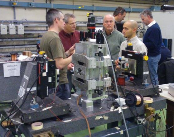
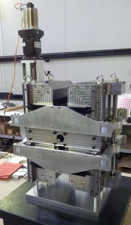
56 drive beam Recently installed 2-beam acceleration module in CTF3 (according to latest CLIC design) main beam Lucie Linssen, March 5th
")
57 Module mechanical characterisation test stand: active alignment, fiducialisation + stabilisation (PACMAN) 57
58 CLIC Higgs physics processes 58
59 CLIC Review 59
60 Key recommendations Produce optimized, staged design: 380 GeV 3 TeV Optimise cost and power consumption Support efforts to develop high-efficiency klystrons Develop 380 GeV klystron-only version as alternative Consolidate high-gradient structure test results Develop plans for ( preparation phase ) Continue and enhance participation in KEK/ATF2 60
61 Organisation Beam dynamics and design (D. Schulte et al) X-band RF, including high-efficiency klystrons (W. Wuensch et al) Main linac module and drive beam front end (S. Doebert et al) Technical systems (N. Catalan et al) General, incl. ATF2, ILC, CTF3, CLEAR (S. Stapnes et al) 61
62 Organisation Beam dynamics and design (D. Schulte et al) X-band RF, including high-efficiency klystrons (W. Wuensch et al) Main linac module and drive beam front end (S. Doebert et al) Technical systems (N. Catalan et al) General, incl. ATF2, ILC, CTF3, CLEAR (S. Stapnes et al) New implementation WGs preparing for European Strategy input: Baseline parameters and design (D. Schulte et al) Civil engineering, infrastructure, siting (J. Osborne et al) Cost, power, schedule (S. Stapnes et al) Main linac hardware baselining (C. Rossi et al) Novel accelerator methods for future CLIC stages (E. Adli et al) 62

63 CTF3 63
64 CLIC Project Meeting 29 November 2016 R. Corsini CTF3 status CTF3 Experimental Program 2016 CLIC two-beam module tests Power production, stability + control of RF profile (beam loading compensation) RF phase/amplitude drifts along TBL, PETS switching at full power Alignment tests Drive-beam phase feed-forward tests Increase reproducibility Demonstrate factor ~ 10 jitter reduction Drive Beam Dispersion free-steering, dispersion matching, orbit control, chromatic corrections, emittance, stability Beam deceleration + optics check in TBL Ongoing instrumentation tests Wake-Field Monitors Main and Drive beam BPMs 64

 RF phase/amplitude drifts along TBL, PETS switching at full")


65 CLIC Project Meeting 29 November 2016 R. Corsini CTF3 status CTF3 Experimental Program 2016 CLIC two-beam module tests Power production, stability + control of RF profile (beam loading compensation) RF phase/amplitude drifts along TBL, PETS switching at full power Alignment tests Drive-beam phase feed-forward tests Increase reproducibility Demonstrate factor ~ 10 jitter reduction Drive Beam Dispersion free-steering, dispersion matching, orbit control, chromatic corrections, emittance, stability Beam deceleration + optics check in TBL Ongoing instrumentation tests Wake-Field Monitors Main and Drive beam BPMs 65
66 Walter Wuensch Accelerating gradient summary
The CompactLight Project (XLS)
") Funded by the European Union The CompactLight Project () Gerardo D Auria (Elettra-ST) on behalf of the CompactLight Collaboration FLS 2018 March 7 th 2018 1 Outline Context X-ray FELs The Collaboration
Funded by the European Union The CompactLight Project () Gerardo D Auria (Elettra-ST) on behalf of the CompactLight Collaboration FLS 2018 March 7 th 2018 1 Outline Context X-ray FELs The Collaboration
RF considerations for SwissFEL
 RF considerations for H. Fitze in behalf of the PSI RF group Workshop on Compact X-Ray Free Electron Lasers 19.-21. July 2010, Shanghai Agenda Introduction RF-Gun Development C-band development Summary
CLIC Feasibility Demonstration at CTF3
 CLIC Feasibility Demonstration at CTF3 Roger Ruber Uppsala University, Sweden, for the CLIC/CTF3 Collaboration http://cern.ch/clic-study LINAC 10 MO303 13 Sep 2010 The Key to CLIC Efficiency NC Linac for
CLIC Status. D. Schulte for the CLIC collaboration
 CLIC Status D. Schulte for the CLIC collaboration 1 Timeline From Steinar 2 Conclusion of the Accelerator CDR Studies Main linac gradient Ongoing test close to or on target Uncertainty from beam loading
Status of CTF3. G.Geschonke CERN, AB
 Status of CTF3 G.Geschonke CERN, AB CTF3 layout CTF3 - Test of Drive Beam Generation, Acceleration & RF Multiplication by a factor 10 Drive Beam Injector ~ 50 m 3.5 A - 2100 b of 2.33 nc 150 MeV - 1.4
STATUS AND FUTURE PROSPECTS OF CLIC
 STATUS AND FUTURE PROSPECTS OF CLIC S. Döbert, for the CLIC/CTF3 collaboration, CERN, Geneva, Switzerland Abstract The Compact Linear Collider (CLIC) is studied by a growing international collaboration.
The CLIC project. Outline: - Brief introduction - Recent developments/news - Focus for this week CLIC SCHEMATIC
 The CLIC project 100m Outline: - Brief introduction - Recent developments/news - Focus for this week e+ INJECTION DESCENT TUNNEL e- INJECTION DESCENT TUNNEL COMBINER RINGS Key features: High gradient (energy/length)
Towards an X-Band Power Source at CERN and a European Structure Test Facility
 Towards an X-Band Power Source at CERN and a European Structure Test Facility Erk Jensen and Gerry McMomagle CERN The X-Band Accelerating Structure Design and Test-Program Workshop Day 2: Structure Testing
STATUS OF THE SWISSFEL C-BAND LINEAR ACCELERATOR
 Proceedings of FEL213, New York, NY, USA STATUS OF THE SWISSFEL C-BAND LINEAR ACCELERATOR F. Loehl, J. Alex, H. Blumer, M. Bopp, H. Braun, A. Citterio, U. Ellenberger, H. Fitze, H. Joehri, T. Kleeb, L.
Nick Walker DESY MAC
 Nick Walker DESY MAC 4.5.2006 XFEL X-Ray Free-Electron Laser DESY ILC Project Group Accelerator Experimentation Behnke, Elsen, Walker (chair) WP 15, 16 WP 4-7 Accelerator Physics and Design WP 6 High Gradient
5 Project Costs and Schedule
 93 5 Project Costs and Schedule 5.1 Overview The cost evaluation for the integrated version of the XFEL with 30 experiments and 35 GeV beam energy as described in the TDR-2001 yielded 673 million EUR for
L-Band RF R&D. SLAC DOE Review June 15 th, Chris Adolphsen SLAC
 L-Band RF R&D SLAC DOE Review June 15 th, 2005 Chris Adolphsen SLAC International Linear Collider (ILC) RF Unit (TESLA TDR Layout) Gradient = 23.4 MV/m Bunch Spacing = 337 ns Fill Time = 420 µs Train Length
STATUS OF THE INTERNATIONAL LINEAR COLLIDER
 STATUS OF THE INTERNATIONAL LINEAR COLLIDER K. Yokoya, KEK, Tsukuba, Japan Abstract The International Linear Collider (ILC) is the nextgeneration electron-positron collider. Since the publication of the
Precision measurements of beam current, position and phase for an e+e- linear collider
 Precision measurements of beam current, position and phase for an e+e- linear collider R. Corsini on behalf of H. Braun, M. Gasior, S. Livesley, P. Odier, J. Sladen, L. Soby INTRODUCTION Commissioning
Suggested ILC Beam Parameter Range Rev. 2/28/05 Tor Raubenheimer
 The machine parameters and the luminosity goals of the ILC were discussed at the 1 st ILC Workshop. In particular, Nick Walker noted that the TESLA machine parameters had been chosen to achieve a high
CLIC Feasibility Demonstration at CTF3
 CLIC Feasibility Demonstration at CTF3 Roger Ruber Uppsala University, Sweden, KVI Groningen 20 Sep 2011 The Key to CLIC Efficiency NC Linac for 1.5 TeV/beam accelerating gradient: 100 MV/m RF frequency:
Development of beam-collision feedback systems for future lepton colliders. John Adams Institute for Accelerator Science, Oxford University
 Development of beam-collision feedback systems for future lepton colliders P.N. Burrows 1 John Adams Institute for Accelerator Science, Oxford University Denys Wilkinson Building, Keble Rd, Oxford, OX1
SLAC X-band Technology R&D. Tor Raubenheimer DOE Briefing June 11 th, 2010
 SLAC X-band Technology R&D Tor Raubenheimer DOE Briefing June 11 th, 2010 Introduction Overall ARD strategy ILC Program X-band program Compact XFEL and other applications Status and development needs Proposed
Upgrading LHC Luminosity
 1 Upgrading LHC Luminosity 2 Luminosity (cm -2 s -1 ) Present (2011) ~2 x10 33 Beam intensity @ injection (*) Nominal (2015?) 1 x 10 34 1.1 x10 11 Upgraded (2021?) ~5 x10 34 ~2.4 x10 11 (*) protons per
Experience with the Cornell ERL Injector SRF Cryomodule during High Beam Current Operation
 Experience with the Cornell ERL Injector SRF Cryomodule during High Beam Current Operation Matthias Liepe Assistant Professor of Physics Cornell University Experience with the Cornell ERL Injector SRF
Present Status and Future Upgrade of KEKB Injector Linac
 Present Status and Future Upgrade of KEKB Injector Linac Kazuro Furukawa, for e /e + Linac Group Present Status Upgrade in the Near Future R&D towards SuperKEKB 1 Machine Features Present Status and Future
INFN School on Electron Accelerators. RF Power Sources and Distribution
 INFN School on Electron Accelerators 12-14 September 2007, INFN Sezione di Pisa Lecture 7b RF Power Sources and Distribution Carlo Pagani University of Milano INFN Milano-LASA & GDE The ILC Double Tunnel
The Elettra Storage Ring and Top-Up Operation
 The Elettra Storage Ring and Top-Up Operation Emanuel Karantzoulis Past and Present Configurations 1994-2007 From 2008 5000 hours /year to the users 2010: Operations transition year Decay mode, 2 GeV (340mA)
SUMMARY OF THE ILC R&D AND DESIGN
 SUMMARY OF THE ILC R&D AND DESIGN B. C. Barish, California Institute of Technology, USA Abstract The International Linear Collider (ILC) is a linear electron-positron collider based on 1.3 GHz superconducting
RF plans for ESS. Morten Jensen. ESLS-RF 2013 Berlin
 RF plans for ESS Morten Jensen ESLS-RF 2013 Berlin Overview The European Spallation Source (ESS) will house the most powerful proton linac ever built. The average beam power will be 5 MW which is five
Focus of efforts. ILC 2010, Mar/27/10 A. Seryi, BDS: 2
 Beam Delivery System Updates Andrei Seryi for BDS design and ATF2 commissioning teams LCWS 2010 / ILC 2010 March 28, 2010 Plan of the program at ILC2010 Focus of efforts Work on parameter set for a possible
WG2 Group Summary. Chris Adolphsen Terry Garvey Hitoshi Hayano
 WG2 Group Summary Chris Adolphsen Terry Garvey Hitoshi Hayano Linac Options Fest On Thursday afternoon, various experts summarized the linac baseline options. Although hard choices have yet to be made,
Detailed Design Report
 Detailed Design Report Chapter 4 MAX IV Injector 4.6. Acceleration MAX IV Facility CHAPTER 4.6. ACCELERATION 1(10) 4.6. Acceleration 4.6. Acceleration...2 4.6.1. RF Units... 2 4.6.2. Accelerator Units...
30 GHz Power Production / Beam Line
 30 GHz Power Production / Beam Line Motivation & Requirements Layout Power mode operation vs. nominal parameters Beam optics Achieved performance Problems Beam phase switch for 30 GHz pulse compression
Pulsed Klystrons for Next Generation Neutron Sources Edward L. Eisen - CPI, Inc. Palo Alto, CA, USA
 Pulsed Klystrons for Next Generation Neutron Sources Edward L. Eisen - CPI, Inc. Palo Alto, CA, USA Abstract The U.S. Department of Energy (DOE) Office of Science has funded the construction of a new accelerator-based
P. Emma, et al. LCLS Operations Lectures
 P. Emma, et al. LCLS Operations Lectures LCLS 1 LCLS Accelerator Schematic 6 MeV 135 MeV 250 MeV σ z 0.83 mm σ z 0.83 mm σ z 0.19 mm σ δ 0.05 % σ δ 0.10 % σ δ 1.6 % Linac-0 L =6 m rf gun L0-a,b Linac-1
Diamond RF Status (RF Activities at Daresbury) Mike Dykes
 Mike Dykes") Diamond RF Status (RF Activities at Daresbury) Mike Dykes ASTeC What is it? What does it do? Diamond Status Linac Booster RF Storage Ring RF Summary Content ASTeC ASTeC was formed in 2001 as a centre of
Diamond RF Status (RF Activities at Daresbury) Mike Dykes ASTeC What is it? What does it do? Diamond Status Linac Booster RF Storage Ring RF Summary Content ASTeC ASTeC was formed in 2001 as a centre of
Linac 4 Instrumentation K.Hanke CERN
 Linac 4 Instrumentation K.Hanke CERN CERN Linac 4 PS2 (2016?) SPL (2015?) Linac4 (2012) Linac4 will first inject into the PSB and then can be the first element of a new LHC injector chain. It will increase
CLIC FEASIBILITY DEMONSTRATION AT CTF3
 CLIC FEASIBILITY DEMONSTRATION AT CTF3 Abstract The CLIC/CTF3 collaboration is studying the feasibility of a multi-tev electron-positron collider, the so-called CLIC: Compact LInear Collider. The idea
J/NLC Progress on R1 and R2 Issues. Chris Adolphsen
 J/NLC Progress on R1 and R2 Issues Chris Adolphsen Charge to the International Linear Collider Technical Review Committee (ILC-TRC) To assess the present technical status of the four LC designs at hand,
Status of RF Power and Acceleration of the MAX IV - LINAC
 Status of RF Power and Acceleration of the MAX IV - LINAC Dionis Kumbaro ESLS RF Workshop 2015 MAX IV Laboratory A National Laboratory for synchrotron radiation at Lunds University 1981 MAX-lab is formed
Current status of XFEL/SPring-8 project and SCSS test accelerator
 Current status of XFEL/SPring-8 project and SCSS test accelerator Takahiro Inagaki for XFEL project in SPring-8 inagaki@spring8.or.jp Outline (1) Introduction (2) Key technology for compactness (3) Key
New Filling Pattern for SLS-FEMTO
 SLS-TME-TA-2009-0317 July 14, 2009 New Filling Pattern for SLS-FEMTO Natalia Prado de Abreu, Paul Beaud, Gerhard Ingold and Andreas Streun Paul Scherrer Institut, CH-5232 Villigen PSI, Switzerland A new
XFEL High Power RF System Recent Developments
 XFEL High Power RF System Recent Developments for the XFEL RF Group Outline XFEL RF System Requirements Overview Basic Layout RF System Main Components Multibeam Klystrons Modulator RF Waveguide Distribution
4.4 Injector Linear Accelerator
 4.4 Injector Linear Accelerator 100 MeV S-band linear accelerator based on the components already built for the S-Band Linear Collider Test Facility at DESY [1, 2] will be used as an injector for the CANDLE
Overview of the X-band R&D Program
 Overview of the X-band R&D Program SLAC-PUB-9442 August 2002 Abstract T.O. Raubenheimer Stanford Linear Accelerator Center, Stanford University, Stanford, California 94309 USA An electron/positron linear
IOT OPERATIONAL EXPERIENCE ON ALICE AND EMMA AT DARESBURY LABORATORY
 IOT OPERATIONAL EXPERIENCE ON ALICE AND EMMA AT DARESBURY LABORATORY A. Wheelhouse ASTeC, STFC Daresbury Laboratory ESLS XVIII Workshop, ELLETRA 25 th 26 th November 2010 Contents Brief Description ALICE
PEP II Design Outline
 PEP II Design Outline Balša Terzić Jefferson Lab Collider Review Retreat, February 24, 2010 Outline General Information Parameter list (and evolution), initial design, upgrades Collider Ring Layout, insertions,
Digital BPMs and Orbit Feedback Systems
 Digital BPMs and Orbit Feedback Systems, M. Böge, M. Dehler, B. Keil, P. Pollet, V. Schlott Outline stability requirements at SLS storage ring digital beam position monitors (DBPM) SLS global fast orbit
THE NEXT LINEAR COLLIDER TEST ACCELERATOR: STATUS AND RESULTS * Abstract
 SLAC PUB 7246 June 996 THE NEXT LINEAR COLLIDER TEST ACCELERATOR: STATUS AND RESULTS * Ronald D. Ruth, SLAC, Stanford, CA, USA Abstract At SLAC, we are pursuing the design of a Next Linear Collider (NLC)
Status of Elettra, top-up and other upgrades
 Status of Elettra, top-up and other upgrades Emanuel Karantzoulis ELETTRA / Trieste, Italy / 2010 November 25-26 Past and Present Configurations 1994-2007 From 2008 No full energy injection Full energy
PoS(EPS-HEP2015)525. The RF system for FCC-ee. A. Butterworth CERN 1211 Geneva 23, Switzerland
525. The RF system for FCC-ee. A. Butterworth CERN 1211 Geneva 23, Switzerland") CERN 1211 Geneva 23, Switzerland E-mail: andrew.butterworth@cern.ch O. Brunner CERN 1211 Geneva 23, Switzerland E-mail: olivier.brunner@cern.ch R. Calaga CERN 1211 Geneva 23, Switzerland E-mail: rama.calaga@cern.ch
CERN 1211 Geneva 23, Switzerland E-mail: andrew.butterworth@cern.ch O. Brunner CERN 1211 Geneva 23, Switzerland E-mail: olivier.brunner@cern.ch R. Calaga CERN 1211 Geneva 23, Switzerland E-mail: rama.calaga@cern.ch
SLAC ILC Accelerator R&D Program
 SLAC ILC Accelerator R&D Program SLUO Meeting September 26 th, 2005 Tor Raubenheimer SLAC 2005 ILC Program NLC group was redirected towards ILC Developed a program aimed at the topics identified in the
2 Work Package and Work Unit descriptions. 2.8 WP8: RF Systems (R. Ruber, Uppsala)
") 2 Work Package and Work Unit descriptions 2.8 WP8: RF Systems (R. Ruber, Uppsala) The RF systems work package (WP) addresses the design and development of the RF power generation, control and distribution
2 Work Package and Work Unit descriptions 2.8 WP8: RF Systems (R. Ruber, Uppsala) The RF systems work package (WP) addresses the design and development of the RF power generation, control and distribution
Evaluation of Performance, Reliability, and Risk for High Peak Power RF Sources from S-band through X-band for Advanced Accelerator Applications
 Evaluation of Performance, Reliability, and Risk for High Peak Power RF Sources from S-band through X-band for Advanced Accelerator Applications Michael V. Fazio C. Adolphsen, A. Jensen, C. Pearson, D.
Status of BESSY II and berlinpro. Wolfgang Anders. Helmholtz-Zentrum Berlin for Materials and Energy (HZB) 20th ESLS-RF Meeting
 20th ESLS-RF Meeting") Status of BESSY II and berlinpro Wolfgang Anders Helmholtz-Zentrum Berlin for Materials and Energy (HZB) 20th ESLS-RF Meeting 16.-17.11.2016 at PSI Outline BESSY II Problems with circulators Landau cavity
Status of BESSY II and berlinpro Wolfgang Anders Helmholtz-Zentrum Berlin for Materials and Energy (HZB) 20th ESLS-RF Meeting 16.-17.11.2016 at PSI Outline BESSY II Problems with circulators Landau cavity
3 cerl. 3-1 cerl Overview. 3-2 High-brightness DC Photocathode Gun and Gun Test Beamline
 3 cerl 3-1 cerl Overview As described before, the aim of the cerl in the R&D program includes the development of critical components for the ERL, as well as the construction of a test accelerator. The
Oak Ridge Spallation Neutron Source Proton Power Upgrade Project and Second Target Station Project
 Oak Ridge Spallation Neutron Source Proton Power Upgrade Project and Second Target Station Project Workshop on the future and next generation capabilities of accelerator driven neutron and muon sources
DEVELOPMENT OF A 10 MW SHEET BEAM KLYSTRON FOR THE ILC*
 DEVELOPMENT OF A 10 MW SHEET BEAM KLYSTRON FOR THE ILC* D. Sprehn, E. Jongewaard, A. Haase, A. Jensen, D. Martin, SLAC National Accelerator Laboratory, Menlo Park, CA 94020, U.S.A. A. Burke, SAIC, San
PULSED POWER FOR FUTURE LINEAR ACCELERATORS
 PULSED POWER FOR FUTURE LINEAR ACCELERATORS Peter D. Pearce High-energy accelerators High-energy accelerators enable us to collide particle beams together and create conditions believed to be similar to
45 MW, 22.8 GHz Second-Harmonic Multiplier for High-Gradient Tests*
 US High Gradient Research Collaboration Workshop. SLAC, May 23-25, 2007 45 MW, 22.8 GHz Second-Harmonic Multiplier for High-Gradient Tests* V.P. Yakovlev 1, S.Yu. Kazakov 1,2, and J.L. Hirshfield 1,3 1
Accelerator Instrumentation RD. Monday, July 14, 2003 Marc Ross
 Monday, Marc Ross Linear Collider RD Most RD funds address the most serious cost driver energy The most serious impact of the late technology choice is the failure to adequately address luminosity RD issues
Next Linear Collider. The 8-Pack Project. 8-Pack Project. Four 50 MW XL4 X-band klystrons installed on the 8-Pack
 The Four 50 MW XL4 X-band klystrons installed on the 8-Pack The Demonstrate an NLC power source Two Phases: 8-Pack Phase-1 (current): Multi-moded SLED II power compression Produce NLC baseline power: 475
Status of SOLARIS Arkadiusz Kisiel
 Status of SOLARIS Arkadiusz Kisiel Solaris National Synchrotron Light Source Jagiellonian University Czerwone Maki 98 30-392 Kraków www.synchrotron.uj.edu.pl Arkadiusz.Kisiel@uj.edu.pl On behalf of SOLARIS
ILC-LNF TECHNICAL NOTE
 IL-LNF EHNIAL NOE Divisione Acceleratori Frascati, July 4, 2006 Note: IL-LNF-001 RF SYSEM FOR HE IL DAMPING RINGS R. Boni, INFN-LNF, Frascati, Italy G. avallari, ERN, Geneva, Switzerland Introduction For
SPEAR 3: Operations Update and Impact of Top-Off Injection
 SPEAR 3: Operations Update and Impact of Top-Off Injection R. Hettel for the SSRL ASD 2005 SSRL Users Meeting October 18, 2005 SPEAR 3 Operations Update and Development Plans Highlights of 2005 SPEAR 3
CLEX (CLIC Experimental Area)
") CLEX (CLIC Experimental Area) Status and plans G.Geschonke for Hans Braun CERN CT3 coll meetg 2005 CLEX 1 CT3 objectives R1.1 CLIC accelerating structure, R1.2 rive beam scheme with a fully loaded linac
CLEX (CLIC Experimental Area) Status and plans G.Geschonke for Hans Braun CERN CT3 coll meetg 2005 CLEX 1 CT3 objectives R1.1 CLIC accelerating structure, R1.2 rive beam scheme with a fully loaded linac
LHC Beam Instrumentation Further Discussion
 LHC Beam Instrumentation Further Discussion LHC Machine Advisory Committee 9 th December 2005 Rhodri Jones (CERN AB/BDI) Possible Discussion Topics Open Questions Tune measurement base band tune & 50Hz
RF Power Systems, CLIC Drive Beam
 RF Power Systems, CLIC Drive Beam Introduction to RF Power Sources Introduction to CLIC CLIC Drive Beam Quest for efficiency CAS, Zürich, March 3 rd, 2018 Steffen Döbert, BE-RF RF Power Sources and Example
Future Circular Collider Study
 Status and Progress M. Benedikt, F. Zimmermann gratefully acknowledging input from FCC coordination group global design study team and all other contributors LHC SPS PS FCC http://cern.ch/fcc Work supported
Introduction to CTF3. G.Geschonke CERN / PS
 Introduction to CTF3 G.Geschonke CERN / PS Aim of review: Review the technical solutions are they realistic? Give us technical advice Comment on alternatives Guide our funding bodies: CERN Collaborations
The LEP Superconducting RF System
 The LEP Superconducting RF System K. Hübner* for the LEP RF Group CERN The basic components and the layout of the LEP rf system for the year 2000 are presented. The superconducting system consisted of
CMS Upgrade Activities
 CMS Upgrade Activities G. Eckerlin DESY WA, 1. Feb. 2011 CMS @ LHC CMS Upgrade Phase I CMS Upgrade Phase II Infrastructure Conclusion DESY-WA, 1. Feb. 2011 G. Eckerlin 1 The CMS Experiments at the LHC
Overview of NLC/JLC Collaboration *
 SLAC PUB 10117 August 2002 Overview of NLC/JLC Collaboration * K. Takata KEK, Oho, Tsukuba-shi 305-0801, JAPAN On behalf of the NLC Group Stanford Linear Accelerator Center, Stanford, California 94309,
HIGH-INTENSITY PROTON BEAMS AT CERN AND THE SPL STUDY
 HIGH-INTENSITY PROTON BEAMS AT CERN AND THE STUDY E. Métral, M. Benedikt, K. Cornelis, R. Garoby, K. Hanke, A. Lombardi, C. Rossi, F. Ruggiero, M. Vretenar, CERN, Geneva, Switzerland Abstract The construction
LCLS Injector Technical Review
 LCLS Injector Technical Review Stanford Linear Accelerator Center November 3&4 2003 Review Committee Members: Prof. Patrick O Shea Chair University of Maryland Dr. E. Colby Stanford Linear Accelerator
LEP OPERATION AND PERFORMANCE WITH ELECTRON-POSITRON COLLISIONS AT 209 GEV
 LEP OPERATION AND PERFORMANCE WITH ELECTRON-POSITRON COLLISIONS AT 29 GEV R. W. Aßmann, CERN, Geneva, Switzerland Abstract The Large Electron-Positron Collider (LEP) at CERN completed its operation in
LCLS RF Reference and Control R. Akre Last Update Sector 0 RF and Timing Systems
 LCLS RF Reference and Control R. Akre Last Update 5-19-04 Sector 0 RF and Timing Systems The reference system for the RF and timing starts at the 476MHz Master Oscillator, figure 1. Figure 1. Front end
North Damping Ring RF
 North Damping Ring RF North Damping Ring RF Outline Overview High Power RF HVPS Klystron & Klystron EPICS controls Cavities & Cavity Feedback SCP diagnostics & displays FACET-specific LLRF LLRF distribution
LEP Status and Performance in 2000
 LEP Status and Performance in 2 R. Assmann, SL/OP for the SL Division Outline: Operational strategy Overview on luminosity and energy performance Energy reach Luminosity performance Other issues Further
The ESS Accelerator. For Norwegian Industry and Research. Oslo, 24 Sept Håkan Danared Deputy Head Accelerator Division Group Leader Beam Physics
 The ESS Accelerator For Norwegian Industry and Research Oslo, 24 Sept 2013 Håkan Danared Deputy Head Accelerator Division Group Leader Beam Physics The Hadron Intensity Frontier Courtesy of M. Seidel (PSI)
Summary of the 1 st Beam Line Review Meeting Injector ( )
") Summary of the 1 st Beam Line Review Meeting Injector (23.10.2006) 15.11.2006 Review the status of: beam dynamics understanding and simulations completeness of beam line description conceptual design of
Summary of the 1 st Beam Line Review Meeting Injector (23.10.2006) 15.11.2006 Review the status of: beam dynamics understanding and simulations completeness of beam line description conceptual design of
NLC - The Next Linear Collider Project NLC R&D. D. L. Burke. DOE Annual Program Review SLAC April 9-11, 2003
 DOE Annual Program Review SLAC April 9-11, 2003 NLC Activities for the Past Year Accelerator Design centered around ILC-TRC studies. Technology R&D focused on the RF R&D. Modulator, klystron, SLED-II,
Position Resolution of Optical Fibre-Based Beam Loss Monitors using long electron pulses
 Position Resolution of Optical Fibre-Based Beam Loss Monitors using long electron pulses E. Nebot del Busto (1,2, 3), M. J. Boland (4,5), S. Doebert (1), F. S. Domingues (1), E. Effinger (1), W. Farabolini
STATUS OF THE SwissFEL C-BAND LINAC
 STATUS OF THE SwissFEL C-BAND LINAC F. Loehl, J. Alex, H. Blumer, M. Bopp, H. Braun, A. Citterio, U. Ellenberger, H. Fitze, H. Joehri, T. Kleeb, L. Paly, J.-Y. Raguin, L. Schulz, R. Zennaro, C. Zumbach,
Solid State Modulators for X-Band Accelerators
 Solid State Modulators for X-Band Accelerators John Kinross-Wright Diversified Technologies, Inc. Bedford, Massachusetts DTI X-Band Experience Developed and built two completely different NLC-class modulator
The PEFP 20-MeV Proton Linear Accelerator
 Journal of the Korean Physical Society, Vol. 52, No. 3, March 2008, pp. 721726 Review Articles The PEFP 20-MeV Proton Linear Accelerator Y. S. Cho, H. J. Kwon, J. H. Jang, H. S. Kim, K. T. Seol, D. I.
Beam-based Feedback Systems
 Beam-based Feedback Systems Philip Burrows Queen Mary, University of London ILC Beam-based Feedback/Feedforward Systems Intra-train (bunch-bunch) feedback at IP: 3 MHz Pulse-pulse feedback at IP: 5 Hz
SLAC ILC program, International BDS Design, ATF2 facility
 1 May 3, 2005 SLAC ILC program, International BDS Design, ATF2 facility Andrei Seryi May 3, 2005 Seminar at CERN 2 May 3, 2005 Contents SLAC ILC program» following the outline given by Tor Raubenheimer
DESIGN AND PERFORMANCE OF L-BAND AND S-BAND MULTI BEAM KLYSTRONS
 DESIGN AND PERFORMANCE OF L-BAND AND S-BAND MULTI BEAM KLYSTRONS Y. H. Chin, KEK, Tsukuba, Japan. Abstract Recently, there has been a rising international interest in multi-beam klystrons (MBK) in the
Design Studies For The LCLS 120 Hz RF Gun Injector
 BNL-67922 Informal Report LCLS-TN-01-3 Design Studies For The LCLS 120 Hz RF Gun Injector X.J. Wang, M. Babzien, I. Ben-Zvi, X.Y. Chang, S. Pjerov, and M. Woodle National Synchrotron Light Source Brookhaven
Concept and R&D Plans for Project X
 Concept and R&D Plans for Project X Giorgio Apollinari 9 th ICFA Seminar SLAC, Oct. 2008 HB2008 Project X for Intensity Frontier Physics 1 Introduction Intensity Frontier: Needs and Physics Justification
A Facility for Accelerator Physics and Test Beam Experiments
 A Facility for Accelerator Physics and Test Beam Experiments U.S. Department of Energy Review Roger Erickson for the FACET Design Team February 20, 2008 SLAC Overview with FACET FACET consists of four
X-Band Klystron Development at
 X-Band Klystron Development at SLAC Slide 1 The Beginning X-band klystron work began at SLAC in the mid to late 80 s to develop high frequency (4x SLAC s-band), high power RF sources for the linear collider
Future Performance of the LCLS
 Future Performance of the LCLS J. Welch for many* SLAC National Accelerator Laboratory FLS 2010, ICFA Beam Dynamics Workshop on Future Light Sources, March 1-5, 2010. SLAC National Accelerator Laboratory,
KEKB INJECTOR LINAC AND UPGRADE FOR SUPERKEKB
 KEKB INJECTOR LINAC AND UPGRADE FOR SUPERKEKB S. Michizono for the KEK electron/positron Injector Linac and the Linac Commissioning Group KEK KEKB injector linac Brief history of the KEK electron linac
Cooperation Activities for Linear Colliders
 Cooperation Activities for Linear Colliders focusing on the CERN-KEK cooperation Shinichiro Michizono with additional slides from Akira Yamamoto, Walter Wuensch, Steinar Stapnes (presenter) CERN-KEK Committee,
EPJ Web of Conferences 95,
 EPJ Web of Conferences 95, 04012 (2015) DOI: 10.1051/ epjconf/ 20159504012 C Owned by the authors, published by EDP Sciences, 2015 The ELENA (Extra Low Energy Antiproton) project is a small size (30.4
The CMS Detector Status and Prospects
 The CMS Detector Status and Prospects Jeremiah Mans On behalf of the CMS Collaboration APS April Meeting --- A Compact Muon Soloniod Philosophy: At the core of the CMS detector sits a large superconducting
TITLE PAGE. Title of paper: PUSH-PULL FEL, A NEW ERL CONCEPT Author: Andrew Hutton. Author Affiliation: Jefferson Lab. Requested Proceedings:
 TITLE PAGE Title of paper: PUSH-PULL FEL, A NEW ERL CONCEPT Author: Andrew Hutton Author Affiliation: Jefferson Lab Requested Proceedings: Unique Session ID: Classification Codes: Keywords: Energy Recovery,
Program Risks Risk Analysis Fallback Plans for the. John T. Seeman DOE PEP-II Operations Review April 26, 2006
 Program Risks Risk Analysis Fallback Plans for the PEP-II B-FactoryB John T. Seeman DOE PEP-II Operations Review April 26, 2006 OPS Review Topics Are there any PEP-II program risks? Has the laboratory
Commissioning and Performance of the ATLAS Transition Radiation Tracker with High Energy Collisions at LHC
 Commissioning and Performance of the ATLAS Transition Radiation Tracker with High Energy Collisions at LHC 1 A L E J A N D R O A L O N S O L U N D U N I V E R S I T Y O N B E H A L F O F T H E A T L A
CEPC Klystron Development
 CEPC Klystron Development Zusheng Zhou On behalf of High Efficiency RF Source R&D Collaboration Institute of High Energy Physics Sep. 26, 2018, HKUST, Hong Kong 1 Outline Strategy and plan 650MHz/800kW
RF Upgrades & Experience At JLab. Rick Nelson
 RF Upgrades & Experience At JLab Rick Nelson Outline Background: CEBAF / Jefferson Lab History, upgrade requirements & decisions Progress & problems along the way Present status Future directions & concerns
KARA and FLUTE RF Overview/status
 KARA and FLUTE RF Overview/status Nigel Smale on behalf of IBPT and LAS teams Laboratory for Applications of Synchrotron radiation (LAS) Institute for Beam Physics and Technology (IBPT) KARA KIT The Research