The Prez Sez... by Tim N6GP
|
|
|
- Adam Skinner
- 5 years ago
- Views:
Transcription


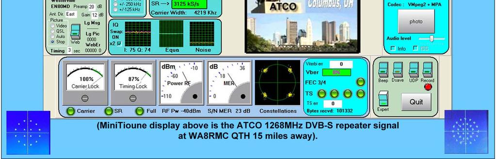
1 VOL. LIX NO. 12 P.O. BOX 3454, TUSTIN, CA December 2018 The Prez Sez... by Tim N6GP Normally, things are winding down at this time, but I have a lot of news. First, I want to report on our excellent Christmas party at Mimi s Café. It was well attended, and I know everyone enjoyed themselves. A big thank you goes to Ron Mudry and the Board for planning the event. Congratulations to prize winners. It was an honor to surprise Ken W6HHC and Bob AF6C with Lifetime Achievement Awards. This is a small token of appreciation for the 5 decades of service that each of them has made to our club. The contributions they have made to our club have been great, and they helped our club through some very lean years about 20 years ago. Our 85 years as a club is a testament to their dedication. Jim Schultz, AF6N, was awarded the Good Of the Club award for his excellent work on the Board in In addition to doing a fine job with his duties as club Secretary, he was always willing to volunteer for special projects. Not the least of these was his shepherding of the 85 th anniversary mugs. He spent a lot of time and his own money developing these mugs, and we really enjoy them. Thanks for a everything you have done, Jim! Lots of news from the ARRL. The Field Day scores are out, and we finished in 19 th place out of 2900! Thanks again to our great FD team, including ABCD ops! Remember, Winter Field day is a month away! This is the last of 24 Prez Sez columns that I ve written. It has been an honor to serve you as President for 2 years, and our Board made the job an easy one. I have passed the Presidential gavel to my friend Dan Violette KI6X, and I am confident that he will be a great President. Tim Goeppinger N6GP, Pres Next General Meeting The January 18 th 2019 OCARC General Meeting program will be presented by Arnie Shatz, N6HC... Baker Island DXpedition The next General Meeting will be on: Friday, January 18, 2019 ENTER from the WEST SIDE entrance of the Red Cross Building, Room 208 Take elevator to the 2 nd Floor. See you there! In This Issue... Page The Prez Sez... 1 Club Information OCARC Holiday Dinner Upcoming Events Lifetime Achievement Awards.7-8 WSJT-X Development..9 Heathkit O-9 to O-12 Scopes OCARC Puzzler RadioActivity 27 General Meeting Minutes Geostationary Es Hail Satellite YTD Cash Flow...32 Successful Ham Radio Ops HB..33 DATV MiniTiouner-Express Rcvr...35 December 2018 OCARC RF Newsletter - Page 1
 348-1636 W6HHC@w6ze.org Membership: Bob Eckweiler AF6C (714) 639-5074 AF6C@w6ze.org Activities: Ron Mudry W6WG (714) 840-3613 W6WG@w6ze.")
 927-4065 W0MEC@w6ze.org Corey Miller KE6YHX (714) 639-5475 KE6YHX@w6ze.")
 (714) 543-9111 WB6IXN@w6ze.org RF Editor for December: Dan Violette KI6X KI6X@w6ze.")
2 2018 Board of Directors: President: Tim Goeppinger N6GP (714) Vice President: Dan Violette Secretary: Jim Schultz AF6N (714) Treasurer: Ken Konechy, W6HHC (714) Membership: Bob Eckweiler AF6C (714) Activities: Ron Mudry W6WG (714) Publicity: Tim Millard, N6TMT (714) Technical: Request Kenan Reilly KR6J for Bouvet DXpedition-2018 (714) Directors-At-Large: Clem Brzoznowski, WØMEC (714) Corey Miller KE6YHX (714) Club Appointments: W6ZE Club License Trustee: Bob Eckweiler, AF6C (714) Club Historian(s) Corey Miller KE6YHX (714) December 2018 OCARC RF Newsletter - Page 2 Bob Evans, WB6IXN (Emeritus) (714) WB6IXN@w6ze.org RF Editor for December: Dan Violette KI6X KI6X@w6ze.org Webmaster: Ken Konechy W6HHC (714) W6HHC@w6ze.org Assistant Webmaster: Bob Eckweiler, AF6C (714) AF6C@w6ze.org Tim Millard, N6TMT (714) N6TMT@w6ze.org ARRL Awards Appointees: Arnie Shatz, N6HC (714) n6hc@aol.com John Schroeder, N6QQ (West Orange Co.) (562) n6qq@msn.com Contact the Newsletter: Feedback & Corrections: rf_feedback@w6ze.org Submit articles: editors@w6ze.org Monthly Events: General Meeting: Third Friday of the month at 7:00 PM held at: American Red Cross 600 Parkcenter Drive Santa Ana, CA (Near Tustin Ave. & 4 th St.) Club Breakfast (Board Mtg): Normally First Saturday of month at 8am Marie Callender s Restaurant 1821 North Grand Ave Santa Ana, CA (Between 17 th & Santa Clara) Club Nets (Listen for W6ZE): ± MHz SSB Wed- 7:30 PM - 8:30 PM Bob AF6C, Net Control Alt: Corey, KE6YHX, Net Control MHz Simplex FM Wed- 8:30 PM - 9:30 PM Corey, KE6YHX, Net Control ± MHz CW OCWN Sun- 9:00 AM 10 AM Ann K6OIO, Net Control ial Support Club Dues for 2018: Regular Members renewals*- - - $30 Family renewal/join** $45 New Member Join Nov-Dec*** $30 Replacement Badge**** $ 3 * Member renewals Jan-Dec. ** Two members or more, w/badge. *** New members Nov thru 2019 w/badge. **** There is a $1.50 charge if you d like to have your badge mailed to you.

 and there are many features added to implement contest operations. 1,250 hams competed in the first ever FT8 contest this month and gave the new version a real test in a contest situation.")

3 More News From Tim Goeppinger N6GP, President The results are in from the ARRL Director elections, and I am pleased to report that 4 of the 5 transparency reform candidates won. Now our SW Div. Director, Dick Norton N6AA, has an 8-7 majority on the ARRL Board. It has been a busy month with the rather new mode FT8 also. The new 2.0 version of WSJT-X was officially released Dec 10 th, and you need to upgrade now if you haven t yet. The new version is not compatible with the old versions (v 1.x.x) and there are many features added to implement contest operations. 1,250 hams competed in the first ever FT8 contest this month and gave the new version a real test in a contest situation. Jim-AF6N (R) accepts the 2018 Good-Of-The-Club Award from President Tim N6GP for his enthusiasm and energy working on club projects. The "Good of the Club Award" is presented annually to the OCARC club member who has made the most significant contribution to the club for the year. In 1997, this annual award was then dedicated to the memory of Kei Yamachika - W6NGO, for his year-after-year contributions in support of our club's activities. Plaques for our Lifetime Achievement Award winners (biographies in this RF). The award is given to a member that has given long time outstanding service to OCARC. This award is only given when there is a deserving person(s) and not on a scheduled basis. December RF Newsletter - Page 3
 and Ken W6HHC (r). Congratulations and thanks for the years of outstanding service.")


4 Our outgoing President, Tim N6GP (center), with our recent Lifetime Achievement Award winners, Bob AF6C (l) and Ken W6HHC (r). Congratulations and thanks for the years of outstanding service. Our outgoing President, Tim N6GP (l), receiving a plaque for his last two years of great leadership to OCARC as our President. This is being given by Dan KI6X, the Vice- President. The prize pool at the banquet. Notice the consolation prize. Appreciate the donation from Nicholas, AF6CF. It was an antique unit which had a great look (not sure it functioned though). December RF Newsletter - Page 4


5 Enjoy the banquet attendees photos and find yourself or your friends having a great time. December RF Newsletter - Page 5


 For the most current Upcoming event information")
 695-0425 has a collection of QST Magazines going")
6 January 18th, 2019 Arnie Shatz, N6HC Baker Island DXPedition Photos and discussion of the recent Baker Island, KH1/KH7Z, DXPedition. Arnie was the medical representative along with all the other duties of preparation, set-up, operating, and teardown., Arnie always brings back interesting presentations from his trips. February 15th, 2019 Doug Millar, K6JEY 10 GHz EME EME = Earth-Moon-Earth March 15th, 2019 William Phinizy, K6WHP Dave Martin, KD6QIY Civil Air Patrol (CAP) For the most current Upcoming event information go to the OCARC EVENTS website: OLD QSTs AVAILABLE - Ralph Houseman, WB6HHA (714) has a collection of QST Magazines going back to 1960 that need a good home. He is located in Yorba Linda. Libraries do not want and don t want to see in trash. December RF Newsletter - Page 6
7 LIFETIME ACHIEVEMENT AWARD BIOGRAPHY Bob Eckweiler, AF6C Bob was born in Manhattan, NY in the mid-forties. His parents lived in Elmhurst, on Long Island at the time. They moved to Manhasset, L.I. a few years later. Bob s dad was a former ham - 2CXX around 1925 but left the hobby to follow a career in mathematics and physics. Bob s ham career started in Junior High in Manhasset NY in 1959 as WV2GUQ thanks to W2CJY, his Elmer. He upgraded to General in a year receiving a WA2 prefix. He took several years off from radio while attending Penn State. Bob moved to California in 1965, finished at Cal State Long Beach with a degree in Physics. The move resulted in a new callsign being issued: WB6QNU. Bob went to work at Douglas Aircraft in Flight & Laboratory Test in June of 1968 designing specialized instrumentation for structural and wind tunnel testing. He spent his whole career at McDonnell Douglas which later became Boeing. He upgraded to Advanced Class in July of 1969 due to the incentive licensing changes. And to Extra Class at the FCC office in Long Beach in November of Bob appreciates the help of Kei, W6NGO and Ted, K6LJA for numerous enjoyable CW QSOs to get his code speed up. In mid-1978 he was assigned his current call AF6C (Not a vanity call!). Bob has been active in OCARC since field day of Has served nearly continually on the Board since the early 1970 s, and also as President in 1973, 1985 and 1996, and has held every officer position. Bob runs the 60 Hz station AKA generator at Field Days, and stores and maintains it at his house ever since a fuel supply problem detracted Field Day in He also operates 20m Phone. Bob s been making the laminated club badges (over 525) since Also, he s written numerous articles for our RF Newsletter including his Heathkit series that are read by hams around the world, and his TechTalk articles (Later Bob s TechTalk ). He puts in countless hours on our website, including most of the heavy coding and also digitized many of the old copies of the RF. A few years ago he taught two soldering classes. He has been our QSL manager, and has been Trustee of our W6ZE callsign for 40 years! Bob has been active on our nets for decades, often as net control. December RF Newsletter - Page 7
8 LIFETIME ACHIEVEMENT AWARD BIOGRAPHY Ken Konechy, W6HHC Ken was born near Pittsburgh PA. When he was 13 he got his novice call of WN3MHI. Ken and a few classmates started a ham radio club while in Junior High school. Upgraded to general as W3MHI. Ken went QRT to go to the University of Pittsburgh, but his ham license helped him qualify for a job at Pitt testing laboratory, first as an electrical technician, then as a research engineer, and got an MSEE degree. He and his family moved to California in 1967, received the W6HHC callsign, and started working at Autonetics (aka Rockwell, Boeing). Also worked at Rainbow Technologies, and in his retirement, has managed the international team that has created DATV-Express, which is a transmitter and a receiver for the amateur form of Digital TV. He has presented this at TAPR and ARRL forums, and other conventions. Ken has served on the OCARC board continuously since late Was Treasurer this year and will be Secretary next year. He has been President 4 times 1974, 1988, 1991, and Along with AF6C he spearheaded the development of the W6ZE website when the internet was just getting started. The website continues to be the envy of other clubs, and Ken continues to keep it up to date. Ken s technical knowledge is vast, and he has shared it with the club over the years. There are RF articles on the website from the late 60 s early 70s that are an excellent tutorial on biasing a transistor. Ken is also a big fan of the Wednesday night nets, and has enjoyed them for years and years. Ken has been a big part of our Field Day efforts since he joined. Can we say every year (all but 2), even at far-away Yucca Valley? The 20-meter phone station is Ken s favorite, as he handles the pileups well. Every year he takes the group photo. He has a tripod and timer on his camera and comes racing back to be in the pictures. * CONGRATULATIONS TO THE LIFETIME ACHIEVEMENT RECIPIENTS * December RF Newsletter - Page 8
9 WSJT-X Development Group Announces Version 2.0 of their Software By Joe Taylor K1JT The WSJT Development Group is pleased to announce the general availability (GA) release of WSJT-X Version on Dec. 10, If you have been using version or earlier, or one of the candidate releases v2.0.0-rc#, it's important to upgrade now. The original protocols for FT8 and MSK144 are no longer supported. With v1.9.1 and earlier you cannot communicate with WSJT-X 2.0 using these modes. We now recommend using WSJT-X 2.0 anywhere in the conventional FT8 and MSK144 sub-bands. Everyone should upgrade to v2.0 by no later than January 1, NEW FEATURES IN WSJT-X Compound and nonstandard callsigns are automatically recognized and handled using new FT8 and MSK144 message formats. 2. The new FT8 protocol provides optimized message formats for North American VHF contests, European VHF contests, ARRL Field Day, and ARRL RTTY Roundup. Similarly, the new MSK144 protocol provides optimized message formats for North American VHF and European VHF contests. Full support is provided for "/R" and "/P" calls in the relevant contests. 3. The new protocols provide nearly equal (or better) sensitivity compared to the old ones, and lower false decode rates. 4. New logging features are provided for contesting and for "Fox" (DXpedition) mode. Logging is optionally integrated with N1MM Logger+ and WriteLog. December RF Newsletter - Page 9 5. Color highlighting of decoded messages provides worked-before status for callsigns, grid locators, DXCC entities, continents, CQ Zones, and ITU zones on a by band and by mode basis, and for stations that have uploaded their logs to Logbook of the World (LoTW) within a specified time interval. 6. The WSPR decoder now achieves decodes down to S/N = -31 db. For the particular benefit of LF/MF users, an option "No own call decodes" has been added. 7. The UDP messages sent to companion programs have been expanded and improved. A more detailed list of program changes can be found in the cumulative Release Notes: ease_notes.txt Upgrading from earlier versions of WSJT-X should be seamless. There is no need to uninstall a previous version or move any files. Please do not continue to use any release candidate -- that is, any beta release with "-rc#" in the version name. Links to installation packages for Windows, Linux, and Macintosh are available here: x.html You can also download the packages from our SourceForge site: It may take a short time for the Source- Forge site to be updated. We hope you will enjoy using WSJT-X Version , Joe, K1JT, for the WSJT Development Group

10 RF Newsletter Orange County Amateur Radio Club Heathkit of the Month #89: by Bob Eckweiler, AF6C ELECTRONIC TEST EQUIPMENT Heathkit O-9 through O-12 Oscilloscopes. Introduction: In the first of this series of articles four Heathkit oscilloscopes, the O-1 through O-4, were discussed. In second article the fifth through eighth Heathkit oscilloscopes, the O-5 through O-8, were discussed 1. This third article discusses the last of the twelve O series oscilloscopes, the O-9 through O-12. The O-1 through O-6 sold for $39.50; the O-7 sold for $43.50, up 10%. The scope performance was improving with each new model and the price was also beginning to increase significantly. The O-8 price, increased almost 37% to $59.50, and the the O-9 through O-12 sold in the $65 to $70 range. To meet the need of lower priced scopes, Heathkit started to release lower-performance ones starting in September These include the 3 OL-1 ($29.50), and the 5 OM-1 through OM-3. ($39.50 but later increased to $49.50, $42.50, $39.95 respectively). Heathkit also produced a couple of higher performance and higher priced oscilloscopes, the Research OR-1 oscilloscope and the Professional OP-1 Oscilloscope. These boasted of a higher performance CRT, the 5ADP2, as well as true DC Here is a link to the index of Heathkit of the Month (HotM) articles: 1 Notes appear at the end of the article Figure 1: The last of the Heathkit O-series scopes, the O-12. Photo by Chuck Penson - WA7ZZE coupling, a sign of an advanced scope. They sold for $ and $ respectively. A schematic and parts list are available online for the O-9 through O-12 (See note 5). Heathkit introduced the O-9 to replace the O-8 in September of It remained in production until replaced by the O-10 in September one year later. The O-10 was released in September of 1954 for $ Since the O-5, Heathkit had been releasing new scopes on a yearly basis in September. However, the O-10 through O-12 were each kept in production for more than one year. December RF Newsletter Page 10!!
 was first advertised in Radio TV News in May of 1958.")
11 RF Newsletter Orange County Amateur Radio Club The O-11 was released in September of 1956, giving the O-10 a production run of two full years. The O-11 also sold for $69.50 and stayed in production for 18 months when it was replaced with the O-12. The final Heathkit O-series oscilloscope, the O-12 (See Figure 1) was first advertised in Radio TV News in May of It came with little fanfare; no New banner, not even any change in the ad description occurred. The only change was the O-11 was replaced with O-12 at the bottom, and the price was reduced from $69.50 to $ The OM-2 was updated to the OM-3 with the same subtlety, and also included a downward price change from $42.50 to $ By late 1960 Radio News 2 had become Electronic World and the Heathkit advertising changed focus from test equipment to audio, amateur and home products. The newly introduced RF-1 RF Signal Generator, FMO-1 FM Test Oscillator and TT-1 Tube Tester were the only test equipment advertised from January through October. In 1960 no Heathkit ads for oscilloscopes were found in Electronic World until November of 1960 when 2 new scopes were introduced, the $76.95 IO-30 which replaced the O-12. and the all-new $79.95 IO-10 DC 3 scope. The O-9 Through O-12 scopes: The last four O -series scopes use a 5UP1 CRT. Heathkit s O-9 advertising emphasizes that this CRT, made by RCA 3, is not surplus, but doesn t have a post deflection accelerator electrode like the O-8. Still, it is a CRT with the benefits of modern design at the time. adjusts the B+ voltages to respond to changes in the unregulated HV CRT voltage, and keeps the CRT trace constant with changes in line voltage. Heathkit continued to update the sweep and sync circuits The O-9 through O-12 scopes allow syncing the sweep to the AC line frequency. It also has line frequency sweep. Note that this is not a linear sweep, but a sinusoidal sweep with no blanking. Table I shows the tube lineup for the O-9 through O-12 scopes. While some of the tubes remain the same between models, oth- Also, starting with the O-9, the scopes feature voltage regulation. In the O-9 this is done with an 0D3 gas regulator tube to keep the important B+ voltages constant. But for the later O-10 through O-12 a newer circuit Figure 2: Heathkit 0-9 Oscilloscope; the last of the Late Pre-Classic style scopes. Photo by Keith Greenhalgh. December RF Newsletter Page 11!!
12 RF Newsletter Orange County Amateur Radio Club O-9 to O-12 Tube Lineup # Function O-9 O-10 O-11 O B+ Rectifier 5Y3 6X4 6X4 6X4 Dual Diode FW 2. HV Rectifier 5Y3 1 1V2 2 1V2 2 1V2 2 1 Parallel diodes }{ 2 HV Rectifier 3. Voltage Regulation 0D3 6C4 6C4 6C4 See text 4. Vertical Input Buffer 6AB4 6AB4 6AB4 6AB4 Triode 5. Vertical Preamplifier #1 ½ 12AT7 3 ½ 6BQ7 3 ½ 6AN8 3 ½ 6AN8 3 3 triode section 6. Vertical Preamplifier #2 ½ 12AT7 3 ½ 6BQ7 3 ½ 6AN8 4 ½ 6AN8 }{ 4 4 pentode section 7. Vertical Phase Splitter 6C4 none none none triode 8. Vertical Deflection Amplifier ½ 12AT7 ½ 12BH7 ½ 12BH7 ½ 12BH7 dual triode 9. Vertical Deflection Amplifier ½ 12AT7 ½ 12BH7 ½ 12BH7 ½ 12BH7 dual triode 10. Horizontal Phase Splitter ½ 12AU7 none none none triode 11. Horizontal Input Buffer none ½ 12AU7 ½ 12AU7 ½ 12AU7 dual triode 12. Horizontal Amplifier none ½ 12AU7 ½ 12AU7 ½ 12AU7 dual triode 13. Horizontal Deflection Amplifier ½ 12AT7 ½ 12AU7 ½ 12AU7 ½ 12AU7 12AT7 dual triode 14. Horizontal Deflection Amplifier ½ 12AT7 ½ 12AU7 ½ 12AU7 ½ 12AU7 }{ 12AU7 dual triode 15. Blanking Amplifier ½ 12AU7 ½ 12AT7 ½ 12AU7 ½ 12AU7 triode section 16. Sweep Multivibrator ½ 12AT7 5 6CB6 6 6DT6 6 ½ 6J6 5 5 triode section }{ 6 pentode 17. Sweep Multivibrator ½ 12AT7 ½ 12AT7 ½ 12AU7 ½ 12AU7 triode section 18. Sync Buffer none none none ½ 6J6 triode section 19. Cathode Ray Tube 5UP1 5UP1 5UP1 5UP1 RCA Mfr. Total Tubes: Total Tube Sections: Table I ers change either to improve performance or possibly due to economic considerations. The following sections contain some circuit discussion. However since the previous two articles cover the circuits in detail, the focus here will be on changes made in each scope. The Heathkit O-9 Oscilloscope: The O-9 is a nice update to the O-8. A new 1V output replaces the 60 CY. TEST binding post. It has a 1V peak-to-peak output, derived from the filament voltage, that can be calibrated by an internal potentiometer. The O-8 is also the first of the O -series scopes to have retrace blanking, since the crude version on the O-1. Due to the new line sweep and sync capability, the front panel layout has changed in places. O-9 Front Panel: The O-9 front panel (refer to Figure 2) is similar to the O-8. The four controls around the CRT remain unchanged. Clockwise from the upper left they are: INTEN., FOCUS, HORI- ZONTAL CENTERING and VERTICAL CEN- TERING. Also the row directly below the CRT remains identical except for the sweep frequency selector ranges; left to right they are: VERT. GAIN, FREQ. SELECTOR and HOR. GAIN. The next row down left to right are the VERT. INPUT attenuator, the FREQ. VERIER and the new line sweep PHASE control. December RF Newsletter Page 12!!
13 RF Newsletter Orange County Amateur Radio Club The next lower row is changed and controls are staggered vertically along the row to accommodate two new control locations that replace two of the slide-switches. This next row and the one below it, from left to right, are: The VERT. INPUT binding post, with its associated GND. below it; The SYNCHRO- NIZING control, which used to be where the PHASE control is now, and below it the EXT. sync binding post; a red jewel pilot lamp, and below it the power OFF - ON slideswitch; the new HOR. SELECTOR 5-position rotary switch and below that the 1V calibration binding post; and finally the HOR. IN- PUT binding post and below that the associated GND post. The five positions of the HOR. SELECTOR switch, in clockwise direction are: EXT. SWEEP, LINE SWEEP, and three internal SWEEP SYNC. positions: LINE, INT. and EXT. The O-9 Circuit Description: There are seven discussion points in the O-9 through O-12 oscilloscope circuits; the B+ and HV power supplies, the vertical amplifier, the horizontal amplifier, the sweep and sync circuits and the blanking amplifier. O-9 B+ Power Supply: A new power transformer is used in the O-9. It is similar in lead color-coding and voltage, but has higher current output in the 700 VAC B+ secondary. The B+ power supply has four voltage outputs, the highest being around 400 volts. An 0D3 volt gas regulator tube provides 150 volts and two other voltages that are tapped off and filtered to drive the lower voltage circuits. The vertical buffer is isolated using one of these voltages; it is not isolated in the O-8. The O-9 uses four 20 µf capacitors in a can, while the O-8 uses two 20 µf and two 10 µf for B+ filtering. December RF Newsletter Page 13!! O-9 HV Power Supply: Since the CRT changed, the resistor voltage divider chain to supply the correct CRT voltages has also changed. Other than that and more HV power supply filtering, the circuit is quite similar to the O-8. O-9 Vertical Amplifier: The O-8 6J5 octal tube vertical input buffer has been replaced with a miniature 6AB4 7- pin triode. The three stage attenuator has not changed except for one resistor to compensate for the bias circuit required for the new tube. The vertical amplifier and driver are similar to the O-8 but include significant component value changes that increase frequency response. The O-9 doubles the O-8 high frequency response at the -2 db point to 2 mc, (3 mc at -6 db). O-9 Horizontal Amplifier: The horizontal amplifier phase splitter is changed from a 6J5 octal tube to a section of a miniature 9-pin 12AU7 dual-triode. The other section is used as the blanking amplifier. Other than that, and a few changes in component values, most notably larger coupling capacitors, and cathode resistors, the circuit is the same as the O-8. O-9 Sweep Oscillator: The sweep circuit is driven from the highest B+ voltage as this allows better sweep linearity. The only change to the sweep generator is an increase in the cathode resistor, perhaps to raise sweep to a more linear portion of the RC charging curve. The sweep ranges remain the same as the O-8. O-9 Sync. Circuit: The sync circuit is identical to the O-8. Instead of using a slide switch to select ± sync, the identical function is inserted in the HOR. SELECTOR switch. In the EXT. SWEEP, and LINE SWEEP positions sync is not connected. In the first of the three SWEEP SYNC positions some of the filament voltage is connect-

14 RF Newsletter Orange County Amateur Radio Club ed to the sync line, and the last two positions, INT. and EXT. imitate the O-8 s slide switch. O-9 Blanking Circuit: A blanking circuit turns off the CRT electron beam while the trace is moving rapidly back from the right side of the screen to the left side. Except for an early attempt with the O-1, Heathkit relied on the rapid movement of the trace back to the left to create such a dim trace that it was acceptable. In most cases it was. In the O-9 Heathkit dedicated the triode section of a 12AU7 tube to turn on during the blanking portion and apply a negative voltage pulse to grid-one of the CRT via the intensity modulation input to turn off the trace. O-9 Construction: Heathkit was continually trying to reduce costs of their kits and at the same time simplify construction whenever they could. The O-9 is the first of the Heathkit oscilloscopes that utilizes a prefabricated wiring harness to simplify construction. While probably more expensive for Heathkit, it offered easier and faster construction and reduced mistakes during assembly. The Heathkit O-10 Oscilloscope: The O-10 (Figure 3) was introduced in September of 1954 with the new Classic I style 4 with a dark gray front panel, white lettering and a slightly lighter gray cabinet. Figure 3: Heathkit 0-10 Oscilloscope; the last of the Late Pre-Classic style scopes. Photo by Chuck Penson. The O-10 has many changes from the O-9. It is the first O-series oscilloscope to use printed circuit boards, and two of them no less. The lower cost OL-1 and OM-1 scopes, introduced the same month, also use circuit boards, though only one in each. And the OL- 1 and OM-1 used the same printed circuit board, though some of the component values are different. The printed circuit board made construction easier and Heathkit s manufacturing costs less. Circuit boards were inexpensive to manufacture in moderate quantities, and the reduction in the cost of chassis machining, mounting hardware, terminal strips, and even some components helped Heathkit keep prices down. The increased ease of construction, and consistent wiring layout resulting in stability between units built, made more complicated kits possible without added difficulty for the builder. Heathkit appeared focused on making their kits easier to assemble and less likely to need to be returned for repair, which probably was a big expense for them. December RF Newsletter Page 14!!
15 RF Newsletter Orange County Amateur Radio Club Besides printed circuit boards, the O-10 also was the first Heathkit scope that used all miniature tubes (excluding the CRT). The three remaining octal tubes of the O-9, the two 5Y3 rectifiers and the OD3 VR tube no longer were used. Another feature of the O-10 is a new voltage regulation circuit. Instead of using a VR tube, the O-10 measures the CRT high voltage and adjusts the B+ voltages to correct the trace deflection when the CRT acceleration voltage changes with line voltage. O-10 Front Panel: The layout of the O-10 front panel appears almost identical to the O-9, color scheme excepted. The obvious change is the OFF - ON slide switch is gone. The fully CCW position of the INTENsity control on the upper left is now marked A.C. OFF. The pilot light remains where it is on the O-9. There are also many less noticeable changes: The FREQ. SELECTOR switch is now marked HOR. / FREQ. SELECTOR with two added positions, EXT. INPUT and LINE SWeep. The SYNCHRONIZING control is now called SYNC AMPLITUDE and it no longer is divided with negative sync to the left of center and positive sync to the right. The HOR. SELECTOR is now named SYNC. SELEC- TOR, and gone are the EXT. INPUT and LINE SWEEP positions; the remaining three positions that were under SWEEP SYNC are now four positions: INT., +INT., LINE and EXT. The last change is the 1-V P-P and the EXT. SYNC. binding posts locations have been swapped. The O-10 Circuit Description: The circuitry of the O-10 shares little with the previous O-series scopes, though the functions remain the same. Heathkit was striving for better vertical bandwidth and December RF Newsletter Page 15!! improved linearity of the sweep circuit. The The O-10 vertical and horizontal amplifiers, except for some minor component changes, remains the same for the O-11 and O-12. The O-10 sweep circuit is described in the manual as utilizing Heath sweep circuit. (Patent applied for.). Still, the circuit was further refined in the O-11 and O-12. O-10 B+ Power Supply: In order to use miniature rectifier tubes the power transformer was changed. The two 5V filament windings for the 5Y3GT tubes are gone. The new seven-pin 6X4 rectifier tube has a 6.3 V heater. The 6.3V winding received a center-tap which is connected to ground; this is possibly to reduce stray 60 cps. radiation within the scope cabinet. Voltage regulation is handled by a 6C4 triode. The grid is connected to the bottom of the CRT high-voltage chain. Should the high voltage increase, due among other reasons by the line voltage changing, the 6C4 grid goes more negative and the tube conducts less, raising the voltages on numerous circuits, increasing the vertical and horizontal gain countering the lower deflection that occurs when the acceleration voltage increases. O-10 HV Power Supply: The 5Y3 rectifier is gone and a nine-pin single diode 1V2 high voltage rectifier tube, which easily handles the 1,200 VDC CRT voltage, replaces it. The new power transformer has a 0.62 V winding for the 1V2 tube filament. This winding is a few extra turns at the top of the high voltage winding. The CRT voltage divider chain is the same as the O-9 except the FOCUS control is 1 MΩ (was 2 MΩ) and a 15 KΩ resistor is added at the bottom of the chain to provide a tap for the voltage regulator circuit.
16 RF Newsletter Orange County Amateur Radio Club O-10 Vertical Circuits: The vertical attenuator circuit was changed from two separate dividers for the x10 and x100 positions to a series divider that handles both. The buffer for the attenuator is also changed adding some feedback to enhance input impedance and high-end frequency response. The output of the buffer is amplified by both sections of a 6BQ7A dual triode in cascade. Each amplifier uses a peaking coil to enhance the vertical response. These coils in effect raise the plate resistance at higher frequencies increasing the gain to compensate for tube loss. While Heath used peaking coils in the vertical driver, this is the first use in the pre-driver stages. The use of peaking coils rule out the use of a phase-splitter for the driver stage. Thus, a new driver circuit that allows position control, synchronization taps and push-pull output was developed. This circuit continued to be used through the O-12 without modification. Referring to Figure 4: The AC signal is coupled to the grid of V3A and then to V3B through the common 1.2KΩ cathode resistor. Since the voltage across this resistor remains nearly constant, when V3A draws more current less current flows through V3B. With the VERTICAL POSITION pot at center, the voltage on the two grids are the same (since no current is flowing, the drop across the 3.3 MΩ resistor is negligible). As the pot is moved the DC bias on the two tubes changes and one tube draws more current. The DC Figure 4 voltage on the vertical deflection plates differ and the trace is moves to a different vertical position on the screen. The 100 Ω resistors in the grid circuit are for parasitic suppression. The plate supply is 300 VDC and the each plate circuit consists of 3.7 KΩ in series with 92 µh. the inductance increases the plate resistance at higher frequencies increasing gain as the tube losses mount, extending the high end frequency response. The driver plates are also coupled to the deflection plates through a coil shunted by a resistor. My guess is that this is to help cancel the wiring and deflection plate capacitance at the higher frequencies. O-10 Horizontal Amplifier Circuit: The O-10 horizontal amplifier/driver is a totally new circuit. It is based on the vertical circuit, without the need to have high gain and high frequency response. The O-10 has a December RF Newsletter Page 16!!
17 RF Newsletter Orange County Amateur Radio Club Figure 5 maximum gain of about 0.6 Vrms per inch of deflection and a frequency response up to about 500 kc. The new circuit is shown in Figure 5. Two 12AU7 dual triodes are used in the horizontal circuits. The first stage acts as a cathode follower buffer. It uses feedback from the cathode to the grid to increase the input impedance. This high impedance is needed due to the new sweep oscillator circuit. The saw-tooth sweep voltage is taken directly from the sweep capacitor. The second half of the first 12AU7 is a simple voltage amplifier with a gain of about 10. It drives the second 12AU7 in basically the same circuit as the vertical driver circuit, but without the added components to increase frequency response. The actual components used are different than the vertical amplifier due to the difference in needed gain and the use of a 12AU7 instead of the higher power 12BH7. December RF Newsletter Page 17!! O-10 Sweep Circuit: Heath called its newly patented sweep circuit for the O-10 a recurrent type. In the O-10 it consists of a pentode and the triode section of a 12AT7. Heath never discussed its operation in their manuals. Here is the author s take on it. See Figure 6: Assume at the beginning (point a on the Cx graph) that V4 is in cutoff and the timing capacitor Cx is discharged. The grid of V5A, thus is highly positive with respect to its cathode and current flows through the tube heavily, rapidly charging Cx. As Cx charges the cathode voltage of V5A climbs until it begins to turn off. The reduction in plate current causes the grid voltage of V4 to climb and it begins to turns on, driving V5A to shut down faster (point b ). With V5A shutdown Cx begins to discharge through the FREQ. VERNIER control and its fixed series resistor. This is the ramp that is amplified
18 RF Newsletter Orange County Amateur Radio Club and fed to the horizontal deflection plates. As the voltage across Cx gets smaller current begins to flow in V5A driving the grid of V4 towards negative and turning it off, which increases the grid voltage, making V5A turn on even faster (point c ). With V5A off Cx begins charging again reaching the point w h e r e Cx is fully charged and V5A is ready to turn on again (point d). The resulting ramp from b to c is fed to the horizontal amplifier to move the trace from left to right at a reasonably constant rate. The speed of the ramp is governed by the speed of discharge of Cx. Coarse adjustment is done by switching the capacitor Cx in approximately decade steps; the fine adjustment is done with the 7.5 MΩ frequency vernier control. O-10 Sync. Circuit: Heath seemed to be trying to continually improve the synchronization circuit. Improvements in the O-10 include separate plus and minus sync selection by a switch, instead of using half the center tapped sync level pot for positive and the other for negative sync. The AC line sync is now fixed, and the phase control only affects the horizontal line sweep. This allows syncing on different parts of the horizontal sweep. The sync signal is fed to the screen grid of the sweep circuit causing it to lock the sweep circuit to the sync signal when the sweep frequency or one of its harmonics is close to the sync signal. Figure 6 O-10 Blanking Circuit: V5B (See full O-10 schematic online 5 ) acts as a blanking amplifier. It is normally conducting. The cathode of the CRT is generally less negative than the first grid. As the voltage gets further apart less beam current flows until the CRT is cutoff. The blanking amplifier, V5B, is capacitively coupled to the plate of V5A. When V5A turns on (at a and c on the Cx voltage graph) a negative pulse is coupled to the grid V5B causing it to turn V5B off. The resulting positive pulse is capacitively coupled to the CRT cathode, making it more positive, cutting off the trace as it rapidly returns to the left of the screen. This is known as the retrace period. O-10 Comments: After nine previous scopes in the O-series, all viable instruments that found a lot of use by TV and radio repairmen, radio amateurs and electronic hobbyists, Heathkit was reaching a point where the O-series oscilloscope design December RF Newsletter Page 18!!

19 RF Newsletter Orange County Amateur Radio Club was close to the best kit scope that could be built for the price. Much of the O-10 circuit design continued to be used on the two final scopes in the series as well as the early IO-series until that series switched to solid-state circuitry. The Heathkit O-11 Oscilloscope: After a two year run the O-10 was updated to the O-11 (Figure 7) in September of A lot of the circuitry remained the same or underwent minor changes. The O-11 sold for $69.50 until April of 1958 when it was superseded with the O-12. O-11 Front Panel: An examination of the O-11 front panel layout shows it to be identical to the O-10 with one simple exception; the pilot lamp lens is no longer a jeweled lens, instead it is a green plastic dome lens. Of course the model number was incremented to O-11 also. The O-11 Circuit Description: There were only minor changes between the O-11 and its predecessor. O-11 Power Supplies: No changes were spotted between the O-10 and O-11 HV nor B+ power supplies. The CRT divider chain remained unchanged as did the voltage regulator circuit, with the exception of the dropping resistor for the 100 V tap. It changed from 1.5 KΩ to 3.3 KΩ. O-11 Vertical Circuits: There were some changes in the buffer/follower circuit. The preamplifier tube was changed from a 6BQ7A dual-triode to a 6AN8 triode/ pentode. At the first vertical amplifier stage (V2A-6AN8 triode section) the plate resistor was increased from 2.2 KΩ to 2.4 KΩ, and the second stage V2B-6AN8 pentode section) the series plate inductor was decreased from 92 to 61 µh and the parallel inductor to the driver was increased to 30 µh. These were probably Figure 7: Heathkit 0-11 Oscilloscope. Except for the pilot lens and model # the front panel is identical to the O-10. Photo by Keith Greenhalgh. done to enhance frequency response to make it more in-spec. The screen of the 6AN8 pentode is connected directly +100 V feeding the two preamplifier stages. O-11 Horizontal Amplifier Circuit: There were no changes from the previous model. Refer to Figure 5 for the O-11 horizontal circuit schematic. O-11 Sweep Circuit: The sweep circuit changes to the O-11 are the 6CB6 (V4) tube has been replaced with a 6DT6 and the 12AT7 (V5) to a 12AU7. This results in a change to the V4 and V5A plate resistors and removal of the V4 cathode re- December RF Newsletter Page 19!!
20 RF Newsletter Orange County Amateur Radio Club sistor and its bypass capacitor. But the remainder of the circuit, its component values and operation remain unchanged as does its function. The reason for the (V4) tube change is discussed in the next section. O-11 Sync. Circuit: The 6DT6 pentode is classified as having two independent control grids. In the O-10 the sync signal is coupled to the screen grid; while in the O-11 it is coupled directly to grid three (the second control grid) which is much more sensitive allowing syncing with a smaller signal. appeared in the June issue with more detail, but no NEW banner. Perhaps it was an advertising deadline driving the May ad. Other changes Heathkit made was adding one resistor to the vertical amplifier and doing another redesign of the sync circuit. O-12 Front Panel: The O-12 front panel appears identical to the O-11 except the model designation and one control. The SYNC. AMPLITUDE control has been renamed to the EXT. SYNC. AMPLITUDE control because the internal sync no longer needs a gain setting. Due to the higher sync. sensitivity Heath changed the SYNC. AMPLITUDE potentiometer from a linear-taper to an audio-taper. A linear-taper control reaches 50% of the full resistance at 50% rotation, while an audiotaper reaches about 10% of the full resistance at 50% rotation. This makes adjustment less critical for large sync signals even with the added sensitivity. O-11 Blanking Circuit: Though V5B has been changed to a 12AU7, the circuit and components remain the same. This tube acts as a switch and is either on or off. The reason for the V5 tube change from a 12AT7 to a 12AU7 is not known. While the 12AT7 was used extensively in O-7 through O-9, only one was used in the O-10. Meanwhile the 12AU7 was being used more. Thus this change could have been for an economic reason and not an engineering reason. The Heathkit O-12 Oscilloscope: In May of 1958 The O-12 appeared, replacing the O-11. The text from the April and May 1958 issues of Radio News are shown in Figure 8. The one significant change between the two scopes was not even mentioned: Heath doubled the sensitivity of the horizontal amplifier to 0.3 volts per inch. A new ad O-12 Power Supplies: No changes of consequence were found in the O-12 power supplies nor in the CRT chain. O-12 Vertical Circuits: The only circuit note was a low value (220 Ω) resistor added between the VERTICAL GAIN control and ground, setting a minimum gain. O-12 Horizontal Amplifier Circuit: Two resistors and a capacitor were changed to double horizontal amplifier sensitivity from 0.6 volts per inch to 0.3 volts per inch. The note in Figure 5 shows the changes. O-12 Sweep Circuit: The 6DT6 vacuum tube (V4) has been replaced with a triode section of a 6J6 dual triode (now V4B). Operation of the sweep circuit continues basically unchanged. O-12 Sync. Circuit: Heath engineers finally separated the sync amplification from the sweep oscillator. The other half of the 6J6 (V4A) is used as a sync amplifier. It also acts as a clipper allowing the scope to sync to waveforms from the vertical amplifier. Since there is no longer a need for a gain control for internal sync. that gain control has been renamed EXT. SYNC AM- PLITUDE. The control remains at the same December RF Newsletter Page 20!!


21 RF Newsletter Orange County Amateur Radio Club Figure 8: On the left is the text from the April 1958 issue of Radio News advertising the O-11; ads with identical text had appeared in earlier issues. On the right is text from the May 1958 issue advertising the O-12. The ad has the identical text, only the model number and price have changed. December RF Newsletter Page 21!! location on the front panel, but now only adjusts the level of an applied external sync signal. The internal sync signals are now coupled to the sweep oscillator by a common cathode resistor between the two triode sections of V4. The End of an Era: In 1960 the O-12 was replaced with a new scope series starting with the IO-30. The IO-30 features a heavier-duty power supply and two fixed sweep frequencies that can be preset and selected from the front panel. It also incorporates a short lived style that was a derivative of the Classic I style. Figure 9: This June 1958 ad shows more information than in May including the new horizontal sensitivity of 0.3 V/in and an increased shipping weight.
22 RF Newsletter Orange County Amateur Radio Club Comments: This is the final article in the O Series Heathkit scope article. These scopes are the first series of test equipment that helped make Heathkit well known as the leader in electronic kits for almost half a decade. Here are a few other pieces of information that might be of interest. Transformers are one of the more expensive pieces of a scope. Originally Heath started out with a heavy WWII surplus transformer. The O-2 transformer was a lot smaller and lighter, but still believed to be war surplus. The O-3 through O-5 used the same transformer, but it was changed for the O-6. Between the O-6 and the O-7 Heath changed its part numbering scheme, so it s hard to say whether they are the same or not. Looking at the schematic, they have identical windings but the O-6 schematic does not give voltages nor currents for the transformer, while the O-7 does. Heath again changed the power transformer for the O-8 and again for the O-9. It was changed again for the O-10, but this transformer continued to be used by the O-11 and the O-12. Table II shows the part numbers of the O -series oscilloscopes. Heath continued to strive to increase the frequency response of these scopes. Probably the biggest reason was for television servicing. A frequency of importance was 4.5 mc so to have a frequency of 5 mc was ideal. Heath reached it, but with some loss with the O-10, O-SERIES POWER TRANSFORMERS O-1 Surplus O O-2 Smaller surplus O O-3 O-72* O O-4 O-72* O O-5 O-72* O O-6 O-125* O * Early Heathkit parts numbering system Table II December RF Newsletter Page 22!! SWEEP FREQUENCY SELECTOR RANGES O-9 a O-10 O-11 / O cps - Line 60 ~ - Line kc kc kc kc kc 5. n/a 10 kc kc 10 kc kc 6. n/a 100 kc kc 100 kc kc a. Same sweep ranges as the O-8 kc = kilocycles, all others are cps (cycles per second) Table III not that the earlier scopes were totally blind at that frequency. The last three scopes are specified at being 5 db down at 5 mc (1 kc reference). this means that if the gain is set so a 1 kc 1 volt signal produces a 2 deflection, then a 5 mc 1 volt signal will produce a deflection of about 1-1/4 inches. With the advent of color television another frequency became important. A scope needed to see the color-burst frequency of 3.58 mc. Thus, starting in 1954, Heath added a spec for the vertical response at that frequency. This was specified at -1.5 db on the O-10, which might have been a bit optimistic because it was lowered to -2.2 db on the two later scopes. Against the same reference as above -2.2 db means a 3.58 mc signal of 2 volts would produce a deflection slightly more than 1-1/2 inches. Heath also spent a lot of effort improving the sweep frequency range. Table III show the ranges as they appear on the front of each of the last four model scopes. These numbers didn t alway jibe with the specifications given in ads and possibly in the manuals. Any little unspecified added range at the ends of the fine sweep control should be thought of as a feature.
23 RF Newsletter Orange County Amateur Radio Club Specification O-9 O-10 O-11 O-12 Announced Date: Discontinued Date: September 1953 August 1954 September 1954 August 1956 September 1956 April 1958 May 1958 November 1960 VERTICAL AMPLIFIER Push - Pull Push - Pull Push - Pull Push - Pull Input Impedance 2 MΩ / 47 µµf (x1) 2 MΩ / 35 µµf (x10/x100) 2.9 MΩ / 21 µµf (x1) 3.4 MΩ / 12 µµf (x10/x100) 2.9 MΩ / 21 µµf (x1) 3.4 MΩ / 12 µµf (x10/x100) 2.9 MΩ / 21 µµf (x1) 3.4 MΩ / 12 µµf (x10/x100) Sensitivity (volts per inch) kc kc kc kc Freq. Response. ± 2 db 10 cps 2 mc ± 6 db 5 cps 3 mc ± 1 db 6 cps 2.5 mc +2 to -5 db 2 cps 5 mc mc ± 1 db 8 cps 2.5 mc +1.5 to -5 db 3 cps 5 mc mc ± 1 db 8 cps 2.5 mc +1.5 to -5 db 3 cps 5 mc mc Attenuator x1 / x10 / x100 x1 / x10 / x100 x1 / x10 / x100 x1 / x10 / x100 HORIZONTAL AMPLIFIER Push - Pull Push - Pull Push - Pull Push - Pull Input Impedance 1 MΩ 30 MΩ / 31 µµf 30 MΩ / 31 µµf 30 MΩ / 31 µµf Sensitivity (volts per inch) 0.6 1kc 0.6 1kc 0.6 1kc 0.3 1kc Freq. Response H Amp. ± 6 db 10 cps 500 cps ± 1 db 1 cps to 200 kc ± 3 db 1 cps to 400 kc ± 1 db 1 cps to 200 kc ± 3 db 1 cps to 400 kc ± 1 db 1 cps to 200 kc ± 3 db 1 cps to 400 kc SWEEP CIRCUIT Multivibrator Recurrent Type Recurrent Type Recurrent Type Horizontal Sweep Range 10 cps to 50 kc 20 cps to 500 kc 20 cps to 500 kc 10 cps to 500 kc Range Switch Positions Line 5 + Line 5 + Line 60-cycle Test Voltage Post Yes, 1 V p to p Yes, 1 V p to p Yes, 1 V p to p Yes, 1 V p to p SYNCHRONIZATION from phase splitter From Vert. amp plate From Vert. amp plate From Vert. amp plate External Input ± Int., ± Ext, Line ± Int., ± Ext, Line ± Int., ± Ext, Line ± Int., ± Ext, Line Power - 50/60 cps 105/120 VAC 70 W 105/125 VAC 80 W 105/125 VAC 70 W 105/125 VAC 70 W Fuse 1½ amp (internal) None 1½ amp (internal) 1½ amp (internal) Electrostatic CRT Shield No No No No Astigmatism (spot) Control Yes Yes Yes Yes Direct Input to CRT Deflection Plates Yes Accessible - See Text Accessible - See Text Accessible - See Text Z Intensity Modulation Input Yes Yes Yes Yes Size H x W x D 14-1/8 x 8-5/8 x /8 x 8-5/8 x /8 x 8-5/8 x /8 x 8-5/8 x 16 Shipping (Net) Weight - lb. 26 (18-1/2) 27 (20-1/2) 21 (20-1/2) 21 (20-1/2) Price US$ $59.50 $69.50 $69.50 $64.95 COLOR KEY: From manual specs. From flyer ads From scope photos or schematic Table IV: Heathkit O-5 through O-8 Specifications (Table notes on next page) December RF Newsletter Page 23!!


24 RF Newsletter Orange County Amateur Radio Club Table V: A timeline of Heathkit O series scopes as well as other scopes offered at the time. Table IV sums up the specifications for the last four O series oscilloscopes, and Table V is a timeline of the twelve O -series scopes and includes the other scopes that Heathkit offered between its epoch and the end of Author Comments: This has been an interesting series to write on. Heathkit was growing up during this period and these kits are a history of that. I have an O-12 and an OL-1 scope that I plan to restore. Many replacement parts are inhouse so I just need the time to get working on them. In the cue is also a Heathkit AR-3, and SW-717 shortwave receiver, and a lot of non Heathkit electronics. In the next few months I ll be writing on some smaller kits so the articles will be shorter, and maybe I ll have time to work on some of the projects too. Next month I plan to cover the GW-31. A handheld transceiver. I had a pair of them back in the very early sixties. 73, from AF6C Notes: 1 The first two articles may be found here: Radio News began in July of 1919 as Radio Amateur News. In July of 1920 the word Amateur was dropped. and in August of 1948 Radio News became Radio & Television News. In April of 1957 it was shortened to Radio & TV News. In May of 1959 the name was changed to Electronics World which remained in publication through In January of 1972 it merged with Popular Electronics. 2 Later, O-10 thru O-12 scopes may use 5UP1 CRTs from other prominent manufacturers (Sylvania, Philips, and others) 4 See Chuck Penson - WA7ZZE s book Heathkit Test Equipment Products for a description of the various test equipment styles starting on page iv. 5 Schematics and parts lists for the O series scopes may be found online at: This article is Copyright 2018 R. Eckweiler, AF6C and The OCARC Inc. Remember, if you are getting rid of any old Heathkit Manuals or Catalogs, please pass them along to me for my research. Thanks - AF6C December RF Newsletter Page 24!!
25 December 2018 Puzzler: As the Christmas dinner was breaking up, two club members decided to play a few rounds of high-card, math-style. Borrowing the ten card deck used for the prize drawing from Ron - W6WG, they proceeded to play two hands. Probably everyone is aware of high-card. where two or more participants draw a card from a deck of cards, and the one with the high card wins. This is often done to see who goes first in another contest. High card math-style is different. There are two players and each draws a single card (in this case from a deck with ten cards, ace through 10, with the ace counting as a one). The rest of the cards are not used. Each player privately looks at his/her card. The winner is not the one with the high card but the first one who KNOWS which player is holding the high card. Each player takes a turn by saying either I have the high card, [My opponent] has the high card, or I don t know. The players that Christmas dinner were Fried - WA6WZO and Bob - AF6C, and it was decided (perhaps by high-card ) that in the first game Fried would go first. The first game proceeded thusly: 1. Fried says: I don t know. 2. Bob says: I don t know. 3. Fried says: I don t know. 4. Bob says: I don t know. 5. Fried says: I have the high card! The question is: There are two possible cards Fried was holding. What are they? In the second game Bob starts first, and the game proceeded thusly: 1. Bob says: I don t know. 2. Fried says: I don t know. 3. Bob says: Fried is holding the high card. The next question is: There are two possible cards Bob was holding. What are they? Send your answers to puzzler@w6ze.org December RF Newsletter - Page 25
26 Answer to last month s (November 2018) Puzzler: A colleague recently commented; Halloween and Christmas must be the same holiday since their dates are the same! I replied wisely; Huh??? It s true. he replied, while taking out a sheet of paper and writing on it: OCT. 31 = DEC. 25 Oh, you re right! I replied, What you wrote is correct. CAN YOU EXPLAIN WHY THAT IS RIGHT? It is true because OCT. can be an abbreviation for OCTAL as well as OCTOBER and DEC. can be an abbreviation for DECIMAL as well as DECEMBER. The octal numbering system, used heavily in computing when code could be entered using switches on the computer front panel. The switches were in groups of three. An octal digit (base 8) runs from 0 to 7 or 000 to 111 binary. The octal number 31 in decimal is 3 x or 25. Octal has largely gone away, being replaced by hexadecimal (base 16). We had a lot of correct answers. Here they are in alphabetical order by call suffix: AF6C Bob Eckweiler (Hey I had to solve it before I passed it on!) AF6CF Nicholas Haban K6PGH Doug Wood KK6DWD Ron Frank N6TMT Tim Millard KI6E Peter Putnam KI6X Dan Violette K7JA Chip Margell KE6YHX Corey Miller WØMEC Clem Brzoznowski WA7ZZE Chuck Penson KD6NOT Mark Bender December RF Newsletter - Page 26
27 RadioActivity January 2019 DECEMBER RAC Winter Contest: 0000Z to 2359Z Sunday Dec. 29 JANUARY Straight Key Night: 0000Z 2359Z January 1 ARRL RTTY Roundup: 1800Z Saturday January 5 to 2400Z Sunday January 6 ARRL Kids Day: 1800Z 2359Z Sat. January 5 **North American QSO Party / CW: 1800Z Saturday January 12 to 0559Z Sun. January 13 *ARRL January VHF Contest: 1900 UTC Saturday Jan 19 to 0359 UTC Mon. January 21 **North American QSO Party / SSB: 1800Z Saturday January 19 to 0559Z Sun. January 20 *CQ WW 160 Meter / CW: 2200Z Saturday 25 Friday to 2200Z Sunday January 27 *Winter Field Day: 1900Z Sat. Jan. 26 to 1900Z Sun. January 27 PLEASE JOIN THE CLUB EFFORT * Indicates club entries are accepted ** Indicates team entries are accepted Note: When submitting logs for ARRL Contests indicate your club affiliation as Orange County ARC Repeating Activities: Phone Fry Every Tuesday night at 0230Z to 0300Z SKCC Weekend Sprintathon (Straight Key CW) on the first weekend of the month after the 6 TH of the month. 1200Z Sat. to 2359Z Sunday. SKCC Sprint (Straight Key CW) 0000Z to 0200Z on the 4 th Tuesday night (USA) of the month. CWops Every Wednesday 1300Z to 1400Z, 1900Z to 2000Z and Thursday 0300Z to 0400Z Send an to Ron W6WG, w6wg@w6ze.org to have your favorite activity or your recent RadioActivity listed in next month s column. December RF Newsletter - Page 27


28 OCARC GENERAL MEETING MINUTES November 16, 2018 The OCARC General meeting was held at the Red Cross Complex in Santa Ana on November 16, Attendance: We had 31 members, 2 guests and our guest speaker sign the attendance log. The meeting was called to order at 7:05 pm and was followed by the Pledge of Allegiance to the Flag and introductions of the members and guests. November Program: Dan, KI6X introduced the presenter for the evening, John Stanford, KF6I. John s subject for the evening was the history and operation of early spark gap generator transmitters. He brought with him and demonstrated a rotary spark gap transmitter originally operated beginning in 1918 under the call 9YD. A native of Dayton, Ohio, John works full time as a self- employed EMC consultant. First licensed in 1974 as WN8SVN in Dayton, he holds an MSEE from the University of Illinois. John is an avid CW HF and VHF contester and active on 6M FT8. When not busy with his EMC clients, John runs his own Islands Amplifier Co repairing and restoring Alpha Amplifiers. John began his presentation by discussing the history of radio transmission dating prior 1910 at which time transmitters were not subject to licensing and prior to the original Radio Act of 1912 which established a call letter system and Radio Inspectors. He spoke of the 1920 s emergence of vacuum tube transmitters on board ships but continuing to be backed up by legacy spark gap shipboard stations. John brought and demonstrated a spark gap transmitter built in 1914 using primarily $50 worth of household derived parts and capable of an 800-mile range. The transmitter was actually operated under both the 9YD call sign and as a commercial weather broadcast station using the call sign of WCAJ. During the intermission, John made the transmitter available for all present to experience hands on keying of their call on a 100-year-old transmitter. The transmitter arcing was impressive and a bit daunting to those who had never before experienced spark gap operation. The presentation was interesting, fun, and very well received. Tim, N6GP reminded that information about the Holiday Dinner is available on the W6ZE website. Ken, W6HHC is available for payment at this meeting or from the PayPal link available on page 3 of the RF Newsletter. Demonstration of the Ham Radio 9YD Rotary Spark-Gap Transmitter from The light bulb gets power from an six-turn inductor near the antenna tuning coil. Professor Dr. John C. Jensen (center) is shown at the 9YD Ham Radio station at Nebraska Wesleyan University in approximately Steve Jensen W6RHM (current owner of the rotary spark-gap) is the grandson of Dr. J.C. Jensen 9YD. December RF Newsletter - Page 28
29 Intermission was taken from 7:32 till 8:00pm. Business Meeting: Club Officers: There was a quorum. All officers were present with the exception of Ron W6WG and Kenan KR6J. Election of Officers and Directors: Jim, AF6N, as club secretary, conducted the election of the 2019 OCARC Officers and Directors. The Nominating Committee s slate for each position was presented and included a contest for President including Nicholas, AF6CF and Dan, KI6X. A secret ballot was taken and Dan, KI6X was elected. The Committee s slate listed two names for Member at Large. They were Tim, N6GP (Automatic as outgoing President) and Clem W0MEC. Nicholas, AF6CF was nominated from the floor, therefore requiring a secret ballot between him and Clem, W0MEC. The ballot was taken and Nicholas, AF6CF was elected. No other committee slated positions were contested so they were elected by voice vote of the membership. The elected 2019 OCARC Board of Directors will consist of: President Dan Violette, KI6X Vice-President Tim Millard, N6TMT Secretary Ken Konechy, W6HHC Treasurer Greg Bohning, W6ATB Activities Ron Mudry, W6WG Membership Corey Miller, KE6YHX Public Relations Vijay Anand, KM6IZO Technical Bob Eckweiler, AF6C Director at Large Tim Goeppinger, N6GP Director at Large Nicholas Haban, AF6CF Announcements: Arnie, N6HC gave a brief report on the successful Ducie Island DXpedition. Final count of contacts was approximately 120,000 including increasing popularity of FT8 operation. Arnie recommends our use of FT8 including Ver. 2.0 beginning in December. Arnie and Chip, K7JA will deliver a future lesson on use of Fox/Hound FT8. Arnie enthusiastically recommends the use of FT8 and also comments that 30 to 40 watts is really all that is required for successful contacts. He also reported that the Braveheart crew was a great help, the Elecraft equipment performed flawlessly, and that only one operator was injured during site set up. Chip, K7JA moved for a vote of thanks for the work of the outgoing Board especially for President Tim, N6GP. The motion passed and was unanimously approved. Tim, N6GP announced that during the past month five new ARRL Directors have been elected. Tim reminded everyone that Winter Field Day is coming up on the fourth weekend in January at the Ocean View School District Office site located at Pinehurst Lane in Huntington Beach. With the inclusion of the ABC group we hope to field 5 transmitters this year. Tim reported the 2018 ARRL Field Day results. OCARC placed 2 nd in the 7-transmitter category and 19 th overall out of some 2900 entries. Good of the Club: Bob, AF6C reported our newest member, Keith, KM6WME ed that both of his nephews lost their houses up state in the Camp Fire and Keith s brother has possibly lost his as well. Jeff, KK6YUP reported that the local Red Cross has deployed few people to the Ventura/Malibu area fire due to local staffing needs. Meeting Adjourned at 8:58 pm Submitted by Jim Schultz, AF6N OCARC Secretary December RF Newsletter - Page 29

30 Geostationary Es Hail-2 Satellite with Ham Radio Digital-ATV Launched November 15, 2018 by Ken Konechy W6HHC The Es Hail-2 satellite on board a SpaceX Falcon 9 launch vehicle was launched from Cape Canaveral on From a concept proposed by the Qatar Amateur Radio Society, the Es Hail (the Qatar Satellite Company) developed the geostationary Es Hail-2 communications spacecraft that also provides two transponders (AMSAT Phase 4-A) for use by radio amateurs. Es Hail-2 will provide a 250 khz linear transponder intended for conventional analog operations (CW, SSB, FM) in addition to another transponder which will have an 8 MHz bandwidth. The latter transponder is intended for experimental digital modulation schemes and DVB amateur television. Think of the wideband transponder as an 8 MHz-wide bent-pipe. The technical design support of the two ham transponders is under the leadership of AMSAT-DL. The geostationary position will give coverage of Europe, Africa, Asia out to Thailand, and a piece of Brazil. Map of signal coverage for the two Ham Radio transponders (courtesy of AMSAT-DL) Narrowband (250 KHz) Linear transponder MHz Uplink MHz Downlink Wideband (8.0 MHz) Digital transponder MHz Uplink MHz Downlink There is a YouTube video of the AMSAT-UK conference presentation on the ham radio DATV transponder given in July 2016 by Dave G8GKQ of the British Amateur Television Club (BATC). Also, a recent issue of the BATC magazine, CQTV (Issue No. 261 Autumn), contains great articles about the Es hail 2 communications satellite, including the proposed bandplan, and a useful 10 GHz LNB to consider for receiving the downlink ( across the pond, of course) December RF Newsletter - Page 30

31 While this satellite coverage does not reach United States or any part of North America, Peter Guelzow DB2OS (President of AMSAT-DL) has explained that this ground breaking project is expected to provide an exciting new phase of activity for radio amateurs for the 21st century. Noel G8GTZ of the BATC posted that the satellite has been positioned into a test orbital slot, and that the In Orbit Testing (IOT) procedures will take a few months to complete. During IOT, the ham radio payload will not be turned on. Once IOT is complete there will be an announcement by AMSAT-DL when the transponders are available for use. However, John GI7UGV reported on the BATC Forum (Forum.BATC.ORG.UK) that an interesting (but temporary) 8 MHz-wide signal on 10 GHz had been spotted on An interesting horizontal polarized 8 MHz-wide signal captured by GI7UGV in the correct location of Es Hail-2 satellite. The signal-gap in the middle was caused by switching the antenna to vertical polarization. (courtesy of John GI7UGV and BATC Forum) December RF Newsletter - Page 31
32 December RF Newsletter - Page 32

33 The Successful Ham Radio Operator's Handbook This new book is aimed at new or returning hams, to help them understand the practical aspects of the hobby, how to use their radios, build antennas and baluns, and get on the air successfully. In it you will find explanations of how the various parts of your ham radio - the transmitter and receiver work, plus how these are being implemented using software defined radio technology. Operating techniques for VHF/UHF repeaters, HF radio DXing techniques, and the new digital modes are covered. Radio propagation, antennas, transmission lines, SWR and the mysteries of baluns are explained. Building your HF station, choosing a radio, connecting your radio to a computer, and mobile and portable operation are extensively covered. Both the pdf and spiral-bound printed versions are available from Lulu.com, and the print copy is also sold by DX Engineering. You can find them via the links below: Here is a link that describes the book in more detail: Follow us on to keep up-to-date on book news and to be notified of book discounts at This book has 267 pages, 211 figures and diagrams, and 53 tables of data to make understanding the sometimes complicated ham radio operations much easier. The book follows KE7X's philosophy of presenting material in several forms to accommodate people with different learning styles -- reading, visualizing, hands-on -- with the many figures and text explanations and there are hands-on exercises throughout the book that can help you learn more about your particular radio. Follow us on to keep up-to-date on book news and to be notified of book discounts at One instructor for new and advanced ham classes has said, This book is exactly what is needed. I've seen some other books targeting the new hams that are less than satisfying both technically and in content but this one is right on the mark and covers so much information that I so often get asked about, during and after teaching classes. December RF Newsletter - Page 33
34 Here are more details on the content: With nearly 110 years of ham radio experience between them, the authors are still excited about the challenges this wonderful hobby offers. The Successful Ham Radio Operator's Handbook will guide you when exploring some of these. Its goal is to help new operators and returning old-timers learn about the breadth of exciting ham radio activities and challenges available today. It answers the question "Why is ham radio relevant in the Internet age?" It covers a wide range of topics, helping the reader to understand the excitement of different facets of ham radio and to choose a challenging and exciting activity to pursue. It helps the reader better understand how the radio works. Many hams only use a small fraction of the features of their radio. For example, if you understand how a noise blanker or a roofing filter or the AGC works, you will be able to more easily use these, and other, features of your radio to your benefit. It provides exercises designed to apply the knowledge to cement your understanding of how your radio works without being radio-specific. It is good for all makes and models. It helps the reader get enough background to understand much of the jargon hams who pursue special activities, such as the various digital modes, VHF contesting and moon bounce. It quickly takes the novitiate reader to higher level of understanding and provides URLs and websites that help the reader go deeper into new interests. Antennas remain a key area where all hams can still successfully experiment and create a key part of their station. This book provides information to help new hams get started cutting their own verticals and dipoles. It explains why some popular multiband antennas may have compromises that impact performance. It gives practical guidelines about choosing transmission lines and building and using baluns and chokes. Digital modes such as RTTY, PSK and the new WSTJ modes are plained. The computer-to-radio connections needed for these modes are discussed and illustrated. Many hams are motivated by public service and emergency preparedness. This book describes typical local emergency organizations and national networks. Hams who like to operate while traveling will find practical information on reciprocal international agreements and how to get permission to operate legally. HAPPY NEW YEAR 2019 December RF Newsletter - Page 34

35 December RF Newsletter - Page 35
HOM rev. new Heathkit of the Month #87: by Bob Eckweiler, AF6C. Heath of the Month #87 - Heathkit O-Series Oscilloscopes - Part II
 Heathkit of the Month #: by Bob Eckweiler, AF6C! ELECTRONIC TEST EQUIPMENT Heathkit O- through O- Oscilloscopes. Introduction: In the June RF Newsletter the first four Heathkit Oscilloscopes were discussed;
The Prez Sez... by Tim N6GP
 VOL. LIX NO. 06 P.O. BOX 3454, TUSTIN, CA 92781-3454 June 2018 The Prez Sez... by Tim N6GP It is June, and It s the Most Wonderful Time of the Year, because Field Day is only about 2 weeks away, and there
ORANGE COUNTY AMATEUR RADIO CLUB, INC. VOL. LIII NO. 12 P.O. BOX 3454, TUSTIN, CA December 2012
 RF ORANGE COUNTY AMATEUR RADIO CLUB, INC. VOL. LIII NO. 12 P.O. BOX 3454, TUSTIN, CA 92781-3454 December 2012 The Prez Sez... by Paul W6GMU As 2012 draws to a close, I d like to thank the Club membership
OPERATING INSTRUCTIONS FOR SYLVANIA. Type I08 Cathode-Ray Oscilloscope. Sylvania Electric Products Inc. Industrial Apparatus. Emporium, Pennsylvania
 OPERATING INSTRUCTIONS FOR SYLVANIA Type I08 Cathode-Ray Oscilloscope Sylvania Electric Products Inc. Industrial Apparatus Plant Emporium, Pennsylvania OPERATING INSTRUCTIONS FOR Sylvania Type 08 Cathode-Ray
CATHODE RAY OSCILLOSCOPE. Basic block diagrams Principle of operation Measurement of voltage, current and frequency
 CATHODE RAY OSCILLOSCOPE Basic block diagrams Principle of operation Measurement of voltage, current and frequency 103 INTRODUCTION: The cathode-ray oscilloscope (CRO) is a multipurpose display instrument
CHAPTER 4 OSCILLOSCOPES
 CHAPTER 4 OSCILLOSCOPES 4.1 Introduction The cathode ray oscilloscope generally referred to as the oscilloscope, is probably the most versatile electrical measuring instrument available. Some of electrical
Nutube.US. 6P1 Evaluation Board. User Manual
 Nutube.US 6P1 Evaluation Board User Manual Introduction The 6P1 Evaluation Board (EVB) is a vehicle for testing and evaluating the Korg Nutube 6P1 dual triode in audio circuits. This product is designed
ORANGE COUNTY AMATEUR RADIO CLUB, INC. VOL. LIII NO. 07 P.O. BOX 3454, TUSTIN, CA July 2012
 RF ORANGE COUNTY AMATEUR RADIO CLUB, INC. VOL. LIII NO. 07 P.O. BOX 3454, TUSTIN, CA 92781-3454 July 2012 The Prez Sez... by Paul W6GMU Member Bob KJ6VQW created a 3-minute YouTube video of the OCARC FD
16 Stage Bi-Directional LED Sequencer
 16 Stage Bi-Directional LED Sequencer The bi-directional sequencer uses a 4 bit binary up/down counter (CD4516) and two "1 of 8 line decoders" (74HC138 or 74HCT138) to generate the popular "Night Rider"
Electrical and Electronic Laboratory Faculty of Engineering Chulalongkorn University. Cathode-Ray Oscilloscope (CRO)
") 2141274 Electrical and Electronic Laboratory Faculty of Engineering Chulalongkorn University Cathode-Ray Oscilloscope (CRO) Objectives You will be able to use an oscilloscope to measure voltage, frequency
2141274 Electrical and Electronic Laboratory Faculty of Engineering Chulalongkorn University Cathode-Ray Oscilloscope (CRO) Objectives You will be able to use an oscilloscope to measure voltage, frequency
Elements of a Television System
 1 Elements of a Television System 1 Elements of a Television System The fundamental aim of a television system is to extend the sense of sight beyond its natural limits, along with the sound associated
OSCILLOSCOPE AND DIGITAL MULTIMETER
 Exp. No #0 OSCILLOSCOPE AND DIGITAL MULTIMETER Date: OBJECTIVE The purpose of the experiment is to understand the operation of cathode ray oscilloscope (CRO) and to become familiar with its usage. Also
TechTalk123 - The MiniTiouner Receiver/Analyzer for Digital-ATV
 TechTalk123 - The MiniTiouner Receiver/Analyzer for Digital-ATV by Ken W6HHC Jean-Pierre F6DZP has been modifying Digital-ATV receivers for DVB-S protocol with software for years - in order to allow the
Using an oscilloscope - The Hameg 203-6
 Using an oscilloscope - The Hameg 203-6 What does an oscilloscope do? Setting up How does an oscilloscope work? Other oscilloscope controls Connecting a function generator Microphones audio signals and
The Venerable Triode. The earliest Triode was Lee De Forest's 1906 Audion.
 The Venerable Triode The very first gain device, the vacuum tube Triode, is still made after more than a hundred years, and while it has been largely replaced by other tubes and the many transistor types,
The Distortion Magnifier
 The Distortion Magnifier Bob Cordell January 13, 2008 Updated March 20, 2009 The Distortion magnifier described here provides ways of measuring very low levels of THD and IM distortions. These techniques
The Iconoscope TV Camera at W6BM, Berkeley
 November 2016, Rev Jan 2017 The Iconoscope TV Camera at W6BM, Berkeley John Staples, W6BM 1. Background The mechanical television era, dating from the early 1920's, used mechanical scanning technologies
COMPOSITE VIDEO LUMINANCE METER MODEL VLM-40 LUMINANCE MODEL VLM-40 NTSC TECHNICAL INSTRUCTION MANUAL
 COMPOSITE VIDEO METER MODEL VLM- COMPOSITE VIDEO METER MODEL VLM- NTSC TECHNICAL INSTRUCTION MANUAL VLM- NTSC TECHNICAL INSTRUCTION MANUAL INTRODUCTION EASY-TO-USE VIDEO LEVEL METER... SIMULTANEOUS DISPLAY...
CHAPTER 3 SEPARATION OF CONDUCTED EMI
 54 CHAPTER 3 SEPARATION OF CONDUCTED EMI The basic principle of noise separator is described in this chapter. The construction of the hardware and its actual performance are reported. This chapter proposes
Modify the UL40-S2 into a Super-Triode amplifier. Ir. Menno van der Veen
 Modify the UL40-S2 into a Super-Triode amplifier Ir. Menno van der Veen Introduction about modifications: The UL40-S2 is already some years on the market and meanwhile I have received several requests
Multi-Key v2.4 Multi-Function Amplifier Keying Interface
 Multi-Key v2.4 Multi-Function Amplifier Keying Interface ASSEMBLY & OPERATION INSTRUCTIONS INTRODUCTION The Harbach Electronics, LLC Multi-Key is a multi-function external device designed for the safe
THE CT-100 COMMERCIAL COLOR TELEVISION RECEIVER
 THE CT-100 COMMERCIAL COLOR TELEVISION RECEIVER BY L.R. KIRKWOOD AND A.J. TORRE RCA Victor Television Division, Camden, N.J. Summary This paper describes the first commercial color-television receiver
INSTRUMENT CATHODE-RAY TUBE
 Instrument cathode-ray tube D14-363GY/123 INSTRUMENT CATHODE-RAY TUBE mono accelerator 14 cm diagonal rectangular flat face internal graticule low power quick heating cathode high brightness, long-life
The Prez Sez... by Tim N6GP
 VOL. LIX NO. 05 P.O. BOX 3454, TUSTIN, CA 92781-3454 May 2018 The Prez Sez... by Tim N6GP About a week ago, I was still riding the post Visalia DX convention wave of euphoria as I was getting back to the
The Cathode Ray Tube
 Lesson 2 The Cathode Ray Tube The Cathode Ray Oscilloscope Cathode Ray Oscilloscope Controls Uses of C.R.O. Electric Flux Electric Flux Through a Sphere Gauss s Law The Cathode Ray Tube Example 7 on an
Physics 123 Hints and Tips
 Physics 123 Hints and Tips Solderless Breadboards All of the analog labs and most of the digital labs will be built on the Proto-Board solderless breadboards. These provide three solderless breadboard
MASTR II BASE STATION 12/24V POWER SUPPLY 19A149979P1-120 VOLT/60 Hz 19A149979P2-230 VOLT/50 Hz
 Mobile Communications MASTR II BASE STATION 12/24V POWER SUPPLY 19A149979P1-120 VOLT/60 Hz 19A149979P2-230 VOLT/50 Hz CAUTION THESE SERVICING INSTRUCTIONS ARE FOR USE BY QUALI- FIED PERSONNEL ONLY. TO
BTV Tuesday 21 November 2006
 Test Review Test from last Thursday. Biggest sellers of converters are HD to composite. All of these monitors in the studio are composite.. Identify the only portion of the vertical blanking interval waveform
TUBE CONVERTERS EL84. Yellow Jackets Types YJS p. 2 YJSHORT p. 3 YJC p. 3 YJ20 p. 4 YJUNI p. 4 YJ7591 p. 4 YJR p. 5. screen grid 9. control.
 TUBE CONVERTERS Yellow Jackets tube converters allow EL power tubes to be used in place of the most common guitar amp power tubes including L, EL, V, 0, 0 and 9. Most Yellow Jackets provide a substantial
GEKCO SUBCARRIER REFERENCE OSCILLATOR MODEL SRO10 OPERATION/SERVICE MANUAL
 GEKCO MODEL SRO10 SUBCARRIER REFERENCE OSCILLATOR OPERATION/SERVICE MANUAL GEKCO Labs PO Box 642 Issaquah, WA 98027 (425) 392-0638 P/N 595-431 REV 5/98 Copyright c 1998 GEKCO Labs All Rights Reserved Printed
RICHLAND COLLEGE School of Engineering Business & Technology Rev. 0 W. Slonecker Rev. 1 (8/26/2012) J. Bradbury
 J. Bradbury") RICHLAND COLLEGE School of Engineering Business & Technology Rev. 0 W. Slonecker Rev. 1 (8/26/2012) J. Bradbury INTC 1307 Instrumentation Test Equipment Teaching Unit 8 Oscilloscopes Unit 8: Oscilloscopes
RICHLAND COLLEGE School of Engineering Business & Technology Rev. 0 W. Slonecker Rev. 1 (8/26/2012) J. Bradbury INTC 1307 Instrumentation Test Equipment Teaching Unit 8 Oscilloscopes Unit 8: Oscilloscopes
2 MHz Lock-In Amplifier
 2 MHz Lock-In Amplifier SR865 2 MHz dual phase lock-in amplifier SR865 2 MHz Lock-In Amplifier 1 mhz to 2 MHz frequency range Dual reference mode Low-noise current and voltage inputs Touchscreen data display
CATHODE-RAY OSCILLOSCOPE (CRO)
") CATHODE-RAY OSCILLOSCOPE (CRO) I N T R O D U C T I O N : The cathode-ray oscilloscope (CRO) is a multipurpose display instrument used for the observation, measurement, and analysis of waveforms by plotting
CATHODE-RAY OSCILLOSCOPE (CRO) I N T R O D U C T I O N : The cathode-ray oscilloscope (CRO) is a multipurpose display instrument used for the observation, measurement, and analysis of waveforms by plotting
CP-830FP Chassis TX-29E50D TX-29E50D/B TX-29PS12D TX-29PS12F TX-29PS12P SPECIFICATIONS. Order No: PCZ C2
 Order No: PCZ0510103C2 SPECIFICATIONS Power Source: Power Consumption: 220-240V a.c.,50hz 100W Stand-by Power Consumption: 1,5W Aerial Impedance: 75Ω unbalanced, Coaxial Type Receiving System: PAL-I, B/G,
There are many ham radio related activities
 Build a Homebrew Radio Telescope Explore the basics of radio astronomy with this easy to construct telescope. Mark Spencer, WA8SME There are many ham radio related activities that provide a rich opportunity
PrimaLuna DiaLogue Specs Info
 PrimaLuna Tube Equipment Model DiaLogue One Specs PrimaLuna Tube Equipment Model DiaLogue Two Specs PrimaLuna Tube Equipment Model DiaLogue Four Specs PrimaLuna Tube Equipment Model DiaLogue Five Specs
Musical Concepts. Chameleon PC-1T. Circuit Description
 PC-1T PC-1T is the standard Active Board. The input signal is DC coupled. This vacuum tube line stage preamplifier uses a single twin triode(6dj8/6922). It operates as a single-stage per channel grounded
4.9 BEAM BLANKING AND PULSING OPTIONS
 4.9 BEAM BLANKING AND PULSING OPTIONS Beam Blanker BNC DESCRIPTION OF BLANKER CONTROLS Beam Blanker assembly Electron Gun Controls Blanker BNC: An input BNC on one of the 1⅓ CF flanges on the Flange Multiplexer
Lecture 17 Microwave Tubes: Part I
 Basic Building Blocks of Microwave Engineering Prof. Amitabha Bhattacharya Department of Electronics and Communication Engineering Indian Institute of Technology, Kharagpur Lecture 17 Microwave Tubes:
University of Utah Electrical & Computer Engineering Department ECE1050/1060 Oscilloscope
 University of Utah Electrical & Computer Engineering Department ECE1050/1060 Oscilloscope Name:, A. Stolp, 2/2/00 rev, 9/15/03 NOTE: This is a fill-in-the-blanks lab. No notebook is required. You are encouraged
VGA Port. Chapter 5. Pin 5 Pin 10. Pin 1. Pin 6. Pin 11. Pin 15. DB15 VGA Connector (front view) DB15 Connector. Red (R12) Green (T12) Blue (R11)
 DB15 Connector. Red (R12) Green (T12) Blue (R11)") Chapter 5 VGA Port The Spartan-3 Starter Kit board includes a VGA display port and DB15 connector, indicated as 5 in Figure 1-2. Connect this port directly to most PC monitors or flat-panel LCD displays
Chapter 5 VGA Port The Spartan-3 Starter Kit board includes a VGA display port and DB15 connector, indicated as 5 in Figure 1-2. Connect this port directly to most PC monitors or flat-panel LCD displays
Burlington County College INSTRUCTION GUIDE. for the. Hewlett Packard. FUNCTION GENERATOR Model #33120A. and. Tektronix
 v1.2 Burlington County College INSTRUCTION GUIDE for the Hewlett Packard FUNCTION GENERATOR Model #33120A and Tektronix OSCILLOSCOPE Model #MSO2004B Summer 2014 Pg. 2 Scope-Gen Handout_pgs1-8_v1.2_SU14.doc
R2001A/B/C Service Monitor Alignment Sections
 R2001A/B/C Service Monitor Alignment Sections R2001A Depot Alignment Notes R2001A Alignment Section A12 FRNT PNL INTERFACE A3 SCOPE/DVM CONTRC)L SINAD IN 3 ( 6 3 1 KHz NOTCH FIL DET»
18 GHz, 2.2 kw KLYSTRON GENERATOR GKP 24KP 18GHz WR62 3x400V
 18 GHz, 2.2 kw KLYSTRON GENERATOR GKP 24KP 18GHz WR62 3x400V With its characteristics of power stability whatever the load, very fast response time when pulsed (via external modulated signal), low ripple,
HIGH VOLTAGE SWITCH PERFORMANCE OF THE EIMAC X-2159 TETRODE ABSTRACT
 HIGH VOLTAGE SWITCH PERFORMANCE OF THE EIMAC X-2159 TETRODE by Bobby R. Gray High Power Component & Effects Section Techniques Branch Surveillance Division Rome Air Development Center Griffiss Air Force
CR7000. CRT Analyzer & Restorer. Easily Test And Restore CRTs With The Most Complete Tests Available For Added Profit And Security.
 CR7000 CRT Analyzer & Restorer Easily Test And Restore CRTs With The Most Complete Tests Available For Added Profit And Security. S1 New Demands From Higher Performance CRTs Require New Analyzing Techniques
SatLabs Recommendation for a Common Inter-Facility Link for DVB-RCS terminals
 SatLabs Recommendation for a Common Inter-Facility Link for DVB-RCS terminals Version 1.6-06/01/2005 This document is the result of a cooperative effort undertaken by the SatLabs Group. Neither the SatLabs
COHERENCE ONE PREAMPLIFIER
 COHERENCE ONE PREAMPLIFIER OWNER S MANUAL TABLE OF CONTENTS Introduction Features Unpacking Instructions Installation Phono Cartridge Loading Basic Troubleshooting Technical Specifications Introduction
Black Buff Amplifier
 Black Buff Amplifier Users' Manual Rev May 12/14 Mapletree Audio Design Al Freundorfer R. R. 1, Seeley's Bay, Ontario, Canada, K0H 2N0 (613) 387 3830 www.mapletreeaudio.com info@mapletreeaudio.com Copyright
LM MHz RGB Video Amplifier System with OSD
 LM1279 110 MHz RGB Video Amplifier System with OSD General Description The LM1279 is a full featured and low cost video amplifier with OSD (On Screen Display). 8V operation for low power and increased
Synchronization circuit with synchronized vertical divider system for 60 Hz TDA2579C
 FEATURES Synchronization and horizontal part Horizontal sync separator and noise inverter Horizontal oscillator Horizontal output stage Horizontal phase detector (sync to oscillator) Triple current source
MULTIDYNE INNOVATIONS IN TELEVISION TESTING & DISTRIBUTION DIGITAL VIDEO, AUDIO & DATA FIBER OPTIC MULTIPLEXER TRANSPORT SYSTEM
 MULTIDYNE INNOVATIONS IN TELEVISION TESTING & DISTRIBUTION INSTRUCTION MANUAL DVM-1000 DIGITAL VIDEO, AUDIO & DATA FIBER OPTIC MULTIPLEXER TRANSPORT SYSTEM MULTIDYNE Electronics, Inc. Innovations in Television
 Over 5000 VXI cards and mainframes in stock. 1000's of pieces of Test Equipment in stock. Looking for Test Equipment? Visit us on the web at www.recycledequipment.com Recycled Equipment buys, sells, and
Presented by: Amany Mohamed Yara Naguib May Mohamed Sara Mahmoud Maha Ali. Supervised by: Dr.Mohamed Abd El Ghany
 Presented by: Amany Mohamed Yara Naguib May Mohamed Sara Mahmoud Maha Ali Supervised by: Dr.Mohamed Abd El Ghany Analogue Terrestrial TV. No satellite Transmission Digital Satellite TV. Uses satellite
K800 RF AMPLIFIER TUBE UPGRADE
 R. F. Note 107 John Vincent August 5, 1988 K800 RF AMPLIFIER TUBE UPGRADE Contents: 1. Introduction 2. RCA 4648 Operating Experience and Evaluation. 3. Tube Selection Criteria 4. Cost and Availability
Simple Way To Brighten Up A 17 Computer Monitor Picture Tube
 Simple Way To Brighten Up A 17 Computer Monitor Picture Tube By Jestine Yong http://www.electronicrepairguide.com Give a copy to a friend This article is free. You can post this article to your website.
Color Organ Triple Deluxe II.
 http://wwwinstructablescom/id/color-organ-triple-deluxe-ii/ Food Living Outside Play Technology Workshop Color Organ Triple Deluxe II by ledartist on January 13, 2013 Table of Contents Color Organ Triple
CHAPTER 3 OSCILLOSCOPES AND SIGNAL GENERATOR
 CHAPTER 3 OSCILLOSCOPES AND SIGNAL GENERATOR OSCILLOSCOPE 3.1 Introduction The cathode ray oscilloscope (CRO) provides a visual presentation of any waveform applied to the input terminal. The oscilloscope
Flat-Bed Module Recorders
 Flat-Bed Module Recorders Model No. 08376-50 08376-55 08376-60 0115-0192 4/28/00 Table of Contents Introduction...3 Power Requirements...3 Chart Paper Installation...3 Pen Installation...5 Grounding...5
Svetlana 3CX10,000A7/8160
 Svetlana 3CX1,A7/816 High-Mu Power Triode T he Svetlana 3CX1,A7/816 is a high-performance ceramic/metal power triode designed for use in zero-bias, class B RF or audio amplifiers. A modern mesh filament
ORANGE COUNTY AMATEUR RADIO CLUB, INC. VOL. LV NO. 6 P.O. BOX 3454, TUSTIN, CA June 2014
 RF ORANGE COUNTY AMATEUR RADIO CLUB, INC. VOL. LV NO. 6 P.O. BOX 3454, TUSTIN, CA 92781-3454 June 2014 The Prez Sez... by Nicholas AF6CF QST QST QST! June is now here, and you know what this means Field
Build A Video Switcher
 Build A Video Switcher VIDEOSISTEMAS serviciotecnico@videosistemas.com www.videosistemas.com Reprinted with permission from Electronics Now Magazine September 1997 issue Copyright Gernsback Publications,
ECE 5765 Modern Communication Fall 2005, UMD Experiment 10: PRBS Messages, Eye Patterns & Noise Simulation using PRBS
 ECE 5765 Modern Communication Fall 2005, UMD Experiment 10: PRBS Messages, Eye Patterns & Noise Simulation using PRBS modules basic: SEQUENCE GENERATOR, TUNEABLE LPF, ADDER, BUFFER AMPLIFIER extra basic:
PESIT Bangalore South Campus
 SOLUTIONS TO INTERNAL ASSESSMENT TEST 3 Date : 8/11/2016 Max Marks: 40 Subject & Code : Analog and Digital Electronics (15CS32) Section: III A and B Name of faculty: Deepti.C Time : 11:30 am-1:00 pm Note:
INSTRUMENT CATHODE-RAY TUBE
 INSTRUMENT CATHODE-RAY TUBE 14 cm diagonal rectangular flat face domed mesh post-deflection acceleration improved spot quality for character readout high precision by internal permanent magnetic correction
Optimizing BNC PCB Footprint Designs for Digital Video Equipment
 Optimizing BNC PCB Footprint Designs for Digital Video Equipment By Tsun-kit Chin Applications Engineer, Member of Technical Staff National Semiconductor Corp. Introduction An increasing number of video
S op o e p C on o t n rol o s L arni n n i g n g O bj b e j ctiv i e v s
 ET 150 Scope Controls Learning Objectives In this lesson you will: learn the location and function of oscilloscope controls. see block diagrams of analog and digital oscilloscopes. see how different input
N3ZI Digital Dial Manual For kit with Backlit LCD Rev 4.00 Jan 2013 PCB
 N3ZI Digital Dial Manual For kit with Backlit LCD Rev 4.00 Jan 2013 PCB Kit Components Item Qty Designator Part Color/Marking PCB 1 LCD Display 1 LCD 1602 Volt Regulator 1 U1 78L05, Black TO-92 Prescaler
D.W. FEARN. VT-4 Vacuum Tube LC Equalizer. Operating Instructions
 D.W. FEARN VT-4 Vacuum Tube LC Equalizer Operating Instructions HOW TO CONTACT US: Telephone: 215-692-4701 Shipping Address: Hazelrigg Industries 124 Tartan Terrace Chalfont, PA 18914 U.S.A. e-mail: support@hazelriggindustries.com
DEPARTMENT OF THE ARMY TECHNICAL BULLETIN CALIBRATION PROCEDURE FOR AUTOMATIC VIDEO CORRECTOR TEKTRONIX, MODEL 1440 (NSN )
") DEPARTMENT OF THE ARMY TECHNICAL BULLETIN TB 11-5820-861-35 CALIBRATION PROCEDURE FOR AUTOMATIC VIDEO CORRECTOR TEKTRONIX, MODEL 1440 (NSN 5820-00-570-1978) Headquarters, Department of the Army, Washington,
DEPARTMENT OF THE ARMY TECHNICAL BULLETIN TB 11-5820-861-35 CALIBRATION PROCEDURE FOR AUTOMATIC VIDEO CORRECTOR TEKTRONIX, MODEL 1440 (NSN 5820-00-570-1978) Headquarters, Department of the Army, Washington,
THE OPERATION OF A CATHODE RAY TUBE
 THE OPERATION OF A CATHODE RAY TUBE OBJECT: To acquaint the student with the operation of a cathode ray tube, and to study the effect of varying potential differences on accelerated electrons. THEORY:
OWNER S MANUAL MODEL ZP3 REV. DATE 2/2016. Zen Triode Phono Stage Model ZP3.
 Zen Triode Phono Stage Model ZP3 INTRODUCTION The Zen Triode Phono Stage is an all tube, single-ended design built using the popular 12AX7 dual triodes for amplification and equalization and a 12AU7 dual
Hitachi Kokusai Electric Comark LLC
 Hitachi Kokusai Electric Comark LLC TRANSMIT TER OF THE FUTURE Solid State. Broadband. Affordable. The future has arrived. With rapid changes in solid state RF device technologies and design techniques,
14 GHz, 2.2 kw KLYSTRON GENERATOR GKP 22KP 14GHz WR62 3x400V
 14 GHz, 2.2 kw KLYSTRON GENERATOR GKP 22KP 14GHz WR62 3x400V With its characteristics of power stability independent of the load, very fast response time when pulsed (via external modulated signal), low
Protecting ETO Alpha 76A Amplifiers
 Protecting ETO Alpha 76A Amplifiers After acquiring a used Alpha 76A amplifier with 8874 tubes of unknown status, I was very pleased to discover the expensive 8874s were percolating well. However, I was
Metal Electrode Meter
 Metal Electrode Meter INSTRUCTION MANUAL FOR Metal Electrode Meter MODEL 2900 Serial # Date PO Box 850 Carlsborg, WA 98324 U.S.A. 360-683-8300 800-426-1306 FAX: 360-683-3525 http://www.a-msystems.com Version
[ Photos ] [ Wares ] [ Library ] [ Dave's Web ] [ Matt's Web ] Wares [ SWISH ] [ Simple Search ] [ Trunk Calc ]
![[ Photos ] [ Wares ] [ Library ] [ Dave's Web ] [ Matt's Web ] Wares [ SWISH ] [ Simple Search ] [ Trunk Calc ]](/thumbs/85/91698811.jpg "[ Photos ] [ Wares ] [ Library ] [ Dave's Web ] [ Matt's Web ] Wares [ SWISH ] [ Simple Search ] [ Trunk Calc ]") [ Photos ] [ Wares ] [ Library ] [ Dave's Web ] [ Matt's Web ] Wares [ SWISH ] [ Simple Search ] [ Trunk Calc ] Realistic PRO-2006 Hardware Modifications Note Edited on January 1st, 1970, 00:00 UT. Improper
[ Photos ] [ Wares ] [ Library ] [ Dave's Web ] [ Matt's Web ] Wares [ SWISH ] [ Simple Search ] [ Trunk Calc ] Realistic PRO-2006 Hardware Modifications Note Edited on January 1st, 1970, 00:00 UT. Improper
Brief Description of Circuit Functions. The brief ckt. description of V20 107E5 17 Monitor
 Exhibit 4 Brief Description of Circuit Functions The brief ckt. description of V20 107E5 17 Monitor 0. Functional Block Diagram 1. General Description 2. Description of Circuit Diagram A. Power Supply
Integre4. Audiophile integrated amplifier. v1.2
 Owner s Manual Integre4 Audiophile integrated amplifier www.lab12.gr v1.2 Table of Contents It is yours Features Unpacking and Warnings Installation & Placement Front Panel Rear Panel Connections Remote
MODIFYING A SMALL 12V OPEN FRAME INDUSTRIAL VIDEO MONITOR TO BECOME A 525/625 & 405 LINE MULTI - STANDARD MAINS POWERED UNIT. H. Holden. (Dec.
 MODIFYING A SMALL 12V OPEN FRAME INDUSTRIAL VIDEO MONITOR TO BECOME A 525/625 & 405 LINE MULTI - STANDARD MAINS POWERED UNIT. H. Holden. (Dec. 2017) INTRODUCTION: Small open frame video monitors were made
Mapletree Audio Design
 Ultra 4C Preamplifier Mapletree Audio Design Ultra 4C Stereo Phono/Line Preamplifier PS 2D Power Supply User s Manual Rev. Mar. 22, 2019 Mapletree Audio Design R. R. 1, Seeley's Bay, Ontario, Canada, K0H
Tube Cricket Build Guide
 Tube Cricket Build Guide The Tube Cricket is a small-wattage amp that puts out about 1 watt of audio power. With a 12AU7 tube-preamp and a JRC386 power amp, the Tube Cricket gives you great tone in a compact
University of Utah Electrical Engineering Department EE1050/1060 Oscilloscope. Name:, Lab TA:
 University of Utah Electrical Engineering Department EE1050/1060 Oscilloscope Name:, Lab TA: A. Stolp, 2/2/00 rev, 9/14/00 NOTE: This is a fill-in-the-blanks lab. No notebook is required. You are encouraged
MAX11503 BUFFER. Σ +6dB BUFFER GND *REMOVE AND SHORT FOR DC-COUPLED OPERATION
 19-4031; Rev 0; 2/08 General Description The is a low-power video amplifier with a Y/C summer and chroma mute. The device accepts an S-video or Y/C input and sums the luma (Y) and chroma (C) signals into
SETi 40 Integrated Amplifier Single Ended 845 Triode User's Guide and Operating Information
 bel canto SETi 40 Integrated Amplifier Single Ended 845 Triode User's Guide and Operating Information Bel Canto Design February 1999 SETi 40 Single Ended 845 Triode Integrated Amplifier The Bel Canto Design
Valves Artzt circuit (a.k.a. the SRPP and the µ-follower)
") Figure 22 illustrates a design for a vinyl disc preamplifier that I designed and which ran in my own hi-fi system (Brice 1985). It is a slightly unusual design in that it incorporates a cascode input stage
Figure 22 illustrates a design for a vinyl disc preamplifier that I designed and which ran in my own hi-fi system (Brice 1985). It is a slightly unusual design in that it incorporates a cascode input stage
. The vertical pull-in range is approximately 10 Hz at fv = 60 Hz.
 Ordering number: EN2781B Monolithic Linear IC CRT Display Synchronization Deflection Circuit Overview The is a sync-deflection circuit IC dedicated to CRT display use. It can be connected to the LA7832/7833,
INTRODUCTION. The purpose of this report is to describe the present method employed in
 M/123.1 November 3, 1952 INTRODUCTION The purpose of this report is to describe the present method employed in designing and aligning a color television receiver incorporating the Philco Apple Tube. It
Instruction Manual MANLM101070C REV. D0202
 Instruction Manual MANLM0070C REV. D0202 LM-0 LIGHT MONITOR Eddy Company 3590 Niabi Road Apple Valley, CA 92308 Phone: 760-96-8457 Fax: 760-96-8458 Internet address: www.eddyco.com TABLE OF CONTENTS GENERAL
Restoring the Dumont Royal Sovereign Television Receiver. John Staples, CHRS
 February 2017 Restoring the Dumont Royal Sovereign Television Receiver John Staples, CHRS The Dumont RA-119 Royal Sovereign, the 30 inch TV with the largest direct-view screen ever made, was presented
MODEL PA II-R (1995-MSRP $549.00)
") F O R T H E L O V E O F M U S I C MODEL PA II-R (1995-MSRP $549.00) OWNER'S MANUAL AND INSTALLATION GUIDE INTRODUCTION To aid in the exciting and custom installs which installers are performing all over
F O R T H E L O V E O F M U S I C MODEL PA II-R (1995-MSRP $549.00) OWNER'S MANUAL AND INSTALLATION GUIDE INTRODUCTION To aid in the exciting and custom installs which installers are performing all over
THE OPERATION OF A CATHODE RAY TUBE
 THE OPERATION OF A CATHODE RAY TUBE OBJECT: To acquaint the student with the operation of a cathode ray tube, and to study the effect of varying potential differences on accelerated electrons. THEORY:
Service Manual for D9100 Series Digital-Control Color Monitor
 Service Manual for D9100 Series Digital-Control Color Monitor Wells-Gardner Electronics 9500 W. 55 th Street Suite A McCook, Illinois 60525-3605 (708) 290-2100 069X3015-100 Revision: B / E01025 Date: 8-24-00
1995 Metric CSJ SPECIAL SPECIFICATION ITEM 6031 SINGLE MODE FIBER OPTIC VIDEO TRANSMISSION EQUIPMENT
 1995 Metric CSJ 0508-01-258 SPECIAL SPECIFICATION ITEM 6031 SINGLE MODE FIBER OPTIC VIDEO TRANSMISSION EQUIPMENT 1.0 Description This Item shall govern for the furnishing and installation of color Single
Experiment 9A: Magnetism/The Oscilloscope
 Experiment 9A: Magnetism/The Oscilloscope (This lab s "write up" is integrated into the answer sheet. You don't need to attach a separate one.) Part I: Magnetism and Coils A. Obtain a neodymium magnet
VU-1 VU Meter Kit Volume Unit Meter
 VU-1 VU Meter Kit Volume Unit Meter Simplicity Counts, Detail Matters. No part of this document may be reproduced, either mechanically or electronically, posted online on the Internet, in whole or in part,
V6118 EM MICROELECTRONIC - MARIN SA. 2, 4 and 8 Mutiplex LCD Driver
 EM MICROELECTRONIC - MARIN SA 2, 4 and 8 Mutiplex LCD Driver Description The is a universal low multiplex LCD driver. The version 2 drives two ways multiplex (two blackplanes) LCD, the version 4, four
bel canto SEP2 Single Ended Triode Tube Preamplifier User's Guide and Operating Information
 bel canto SEP2 Single Ended Triode Tube Preamplifier User's Guide and Operating Information Bel Canto Design 212 Third Avenue North, Suite 274 Minneapolis, MN 55401 USA Phone: 612 317.4550 Fax: 612.359.9358
ATVC-4 Plus Amateur Television Repeater Controller Copyright Intuitive Circuits, LLC
 ATVC-4 Plus Amateur Television Repeater Controller Copyright 2002-2010 Intuitive Circuits, LLC Description Installing an amateur television repeater takes some real planning and quality equipment. "Thinking
SNG-2150C User s Guide
 SNG-2150C User s Guide Avcom of Virginia SNG-2150C User s Guide 7730 Whitepine Road Revision 001 Richmond, VA 23237 USA GENERAL SAFETY If one or more components of your earth station are connected to 120