INZENNIO Z38. KNX Touch Panel PRODUCT MANUAL ZN1VI TP38. Edition 9 Version 4.3
|
|
|
- Paula Hudson
- 5 years ago
- Views:
Transcription

1 PRODUCT MANUAL INZENNIO Z38 KNX Touch Panel ZN1VI TP38 Edition 9 Version 4.3
2 INDEX 1. INTRODUCTION PRODUCT INSTALLATION CONFIGURATION PARAMETERIZATION GENERAL «DISPLAY BRIGHTNESS» OBJECT PAGES «HOME» & «HOME II» PAGES BINARY CONTROL LIGHT CONTROL SHUTTER CONTROL CLIMA CONTROL BYTE CONTROL SCENE CONTROL TEMPERATURE CONTROL BINARY INDICATOR ONE BYTE INDICATOR FLOATING POINT INDICATOR SECURITY CONTROL PRESENCE SIMULATION SPECIFIC PAGES SCENES SCHEDULE PROGRAMMING CLIMA technical ALARMS CONFIGURATION INPUTS SHORT PRESS ONE BIT SENDING 0/ SHUTTER CONTROL DIMMER CONTROL SENDING A SCENE
3 LONG PRESS THRESHOLD TIME RESPONSE DELAY INPUT LOCK ANNEX I. COMMUNICATION OBJETS ANNEX II. INDIVIDUAL CONTROLS ANNEX III. DOUBLE CONTROLS ANNEX IV. INDICATORS

4 1. INTRODUCTION 1.1. PRODUCT INZennio Z38 is an LCD Touch Panel with Room Thermostat, Binary Inputs and IR Receiver built-in. Some of its most important features are mentioned below: KNX 3.8 back-lighted monochrome Touch Panel Room Thermostat Presence Simulation Full Climate Management 12 Configurable Direct Control Functions 5 Additional Pages with up to 6 independent Functions o Scene Control [5 Functions] o Schedule Programming [4 Functions] o Climate Control [5 Functions] o Technical Alarms [6 Functions] o Display Parameters IR Receiver buit-in (Remote Control) 4 Binary Inputs for Voltage free push buttons. No external supply required. KNX BCU included. Total Data Saving when Power Failure occurs. The Touch Panel InZennio Z38 is organized into "Pages"; every page consists of several "parametrizable boxes" and a "header". HOME PAGE Header MENU Page Shortcut HOME II Shortcut PARAMETRIZABLE BOX IR Receiver Room Thermostat 4

5 The next schema represents available pages to be "enabled" and its hierarchy. Home Page MENU Page Specific Pages Access Home II Page SCENES 1 SCH. PROGRAMMING CLIMA SCENES 2 SCH. PROGRAMMING CLIMA SCENES 3 SCH. PROGRAMMING CLIMA SCENES 3 SCH. PROGRAMMING CLIMA TECHNICAL 5 ALARMS CONFIGURATION 6 Figure 1.1 MENU PAGE Back to Home Page CONFIGURATION PAGE 5
6 Next sections in this manual, will detail the correct way to configure and program the LCD Panel InZennio Z38, so that a user can control all (or part of) the KNX installation from a single device. o <<PAGES>> Home & Home II The Home page is the InZennio Z38 Welcome page; this will be the starting point (once the necessary boxes have been enabled) to access, the most commonly required functions. The "Home II" page is just like the "Home" one, as far as functionality and potential programming terms is concerned. Consider the "Home II" page as an extension of the own "Home" page. MENU Page: Access to Specific Pages Users in this case, have the option to "enable" up to six different pages, and even, when talking about the "Specific 1, 2, 3 & 4" ones, to associate them with a particular function: o o o Scenes Schedule Programming Clima Figure 1.1 shows the schematic page organization in the InZennio Z38 Panel. Note: "Home", "Home II" and the Technical Alarms pages in the InZennio Z38 Panel have 6 parametrizable boxes each. "Clima", Scenes", and the Configuration" pages have 5 parametrizable boxes each, while the Schedule Programming one has only 4 parametrizable boxes 1.2. INSTALLATION Please refer to the Product Data Sheet, for up to date information on the installation of the InZennio Z38 Panel, as well as to gather detailed information on its technical characteristics. The Data Sheet is included in the original packaging of the product, and is available to be downloaded from the website 6

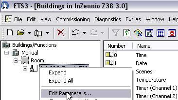
7 1.3. CONFIGURATION The INZennio Z38 includes 217 Communication Objects responsible to transmit and receive data through the BUS. To begin with the InZennio Z38 module configuration, it will be necessary to import in ETS, a project that contains an InZennio Module of the device, or a database.vd file of the product (See www. Zennio.com) This manual starts from the "default" product configuration, to gradually configure the device according to the user requirements. o Default Z38 Panel Configuration (Communication Objects) To make Communication Objects working easier, as well as to facilitate its understanding, these have been reorganized as selected by parameters. The Communication Object arrangement has been also substantially improved by ordering them alphabetically by sections on the ETS. Note: For this arrangement to be effective, it is necessary to click on the NAME column, instead of the NUMBER one. o Parameters will be shown as they appear initially In order to visualise and configure the parameters of an ETS device, click the rightmouse button on the BUS device you want to configure, then click left-mouse button on Edit Parameters. 7
8 o Main Parameterization Window appears 8
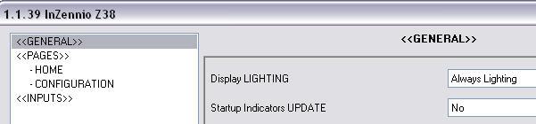
9 2. PARAMETERIZATION Access via ETS to the Main Parameterization Page on the ETS, has three main sections: Every section is detailed next: <<GENERAL>> <<PAGES>> <<INPUTS>> 2.1. GENERAL This parameterization section, allow users to enable the remote control zones as well as to associate them with the Home or Home II pages for its control; this section also allows to configure various aspects of the display backlight and other general parameters. Available configuration options involving the display backlight are represented in the next diagram. DISPLAY BRIGHTNESS Auto Dimming Always ON Dimming Level Status while Dimming Minimum Display Active Off Display Locked (Unlock with a single touch) Figure 2.1 9
10 DISPLAY BRIGHTNESS (Figure 2.1) Always ON: Light on the display remains always ON, even when the page is not in use. Auto Dimming: 45 seconds after the last interaction on the display, this will recover its stand-by mode. o DIMMING LEVEL (Stand-by Mode) o Off: After 45 seconds (Auto Dimming), the own auxiliary light on the display will remain OFF (until a new touch on it is made) Minimum: After 45 seconds (Auto Dimming), the display will light slightly, (this is useful to identify it in dark places). DISPLAY STATUS WHILE DIMMING Display Active: Display remains always active; this means that any interaction with it will obtain an immediate response. Display Locked (unlock with a single touch): The display needs a first touch onto it to be unlocked, after this, this can be normally operated. INDICATORS UPDATE WHEN INITIATING When recovering the BUS voltage (or after a program download), the InZennio Z38 may ask the rest of devices in the installation for their corresponding values, in order to update the display indicators. Delay: This field allows a user to set a delay (in seconds) to put off the indicators update, until the rest of devices on the installation are completely initiated. WEEKDAY INITIALS Seven free characters are available to enter the weekday initials. Both the date and the week-day will appear on any page header, when the Time Zone is pressed. 10
11 Time Zone Date (M) Monday Note: Week days are automatically calculated by the own display when adjusting the date on it. REMOTE CONTROLLER Zone 1: This field will allow users to associate this zone of the control to either any of both Home or Home II pages. Zone 1 Zone 2 Zone 2: This field will allow users to associate this zone of the control to either any of both Home or Home II pages. Note: Buttons arrangement on the remote controller is similar to the Home & Home II boxes structure to make its control easier. TEMPERATURE SENSOR CALIBRATION Allow users to recalibrate the Temperature Sensor referred to the own temperature measured by the sensor itself when the calibration parameter remains unchanged (value 0 ). Example: If we have a really accurate thermometer at home, we can take its measure as a reference for the Z38. Measurement shown by the Z38 internal sensor x ºC Measurement shown by the accurate thermometer y ºC Positive difference between measures x y = z ºC Positive Calibration parameter z ºC Negative difference between measures x y = - z ºC Negative calibration parameter - z ºC 11
12 TEMPERATURE SENDING PERIOD This field is meant to set a period of time for the Z38 to send the registered temperature to the BUS through the Temperature-Internal Sensor value Communication object «DISPLAY BRIGHTNESS» OBJECT The Z38 Panel has a Communication Object Display Brightness which has the same effect than touching onto the display. When this object receives a 1 from the BUS, the display lights up and gets active. A Display active implies that any interaction with it by the user will always get an immediate response, regardless of the Status while Dimming parameterized before. (See page 10) Note: When receiving a 0 nothing happens Example: This functionality allows a presence detector or a door contact to send a 1 to the BUS notifying the user that someone entered the room, or that someone got up during the night. When receiving a 1, the display lights up (either to welcome the user entering the room or to let him see the display in the dark) PAGES This Manual section is intended to detail the different pages the InZennio Z38 provides the user, including the submenus offered in each of these pages. When a Panel page is enabled, two parameterization fields become available: NAME This field allow users to associate a name to any of the InZennio Z38 pages; this name will appear on any of the page headers the user is moving through (12 free characters are available to set the name). Note: The only page which cannot be renamed is the MENU one (to access Specific Pages). SECURITY A restricted page prevents unauthorized access to it. A 4 digits password is required to enter a protected page. The default password is


13 Note: The Home page is enabled by default. Access to the Home page cannot be restricted. 4 DIGITS PASSWORD NAME RESET PASSWORD CANCEL/DELETE Resetting the paswword: 1º Push NEW Old: Enter old password 2º New: Enter new password 3º Repeat: Confirm new password «HOME» & «HOME II» PAGES These two pages are intended to parameterize their boxes so that a user can easily access the most common used functions when controlling an installation. As well as the pages, every box on Home and Home II pages has a parametrizable field: NAME This field allows a user to associate a name with the corresponding box in the page, (11 free characters are available to set the name). BOX 1 BOX 2 SINGLE BUTTON NAME COUPLED BUTTONS 13
14 Note: Home Page will be shown again 90 seconds after last interaction on the display took place BINARY CONTROL This is a generic control to communicate all those devices susceptible to be, by sending a single bit (0 / 1). BUTTON 1 In Binary Control, this button will always appear as enabled by default. Short Press: Choose whether to send: Nothing/0/1 or Toggle to the BUS through its Communication Object. Long Press: Same case than before, the only difference is that now users will need to keep the button on the display pressed during at least 0.5 seconds to send the corresponding data through its Communication Object. ICON: An icon can be associated to the page box. (See Annexe I). BUTTON 2 It might be possible to have two buttons on the same BOX, by simply activating this option in the corresponding field. Although both buttons will transmit data independently; both of them also share the same Communication Object. The way to parameterize this button is the same than the explained for BUTTON 1. Indicator: By activating this parameter, an status indicator will be inserted between both buttons: o ON/OFF o 0/ LIGHT CONTROL This control is specifically designed for lighting control. Through its Communication Objects, users will be able to turn On/Off any kind of incandescent lamps, low voltage lamps, compact fluorescent lamps, and even controlling their output intensity. Note: When trying to control compact fluorescent lamps (CFL), an electronically reactance or a specific KNX actuator would be necessary to control their intensity. 14
15 TYPE Select the control type to use: On/Off: This is the most basic control type; Turn On/Off; pretends to simulate a common switch action. On/Off + Simple Regulation (4 bits): Users can simulate a common switch action, turn On/Off (short press on the buttons), or a discreet regulation (long press on the buttons), where depending on the dimming step set, keeping the button pressed will reduce or increase the brightness on the controlled lamps. Dimming Step: Six different regulation levels are available for this duty. A long press on the display buttons will reduce or increase the brightness level step by step the percentage set in this parameter; once the desired level is reached, stop pressing the button on the display to keep the desired value. Dimming Step Necessary button presses for a complete regulation (0 100%) % % % % % % % 64 Indicator: This will inform users about the brightness percentage applied at any time. Note: In this case, for this indicator to be functional, it is necessary to use a KNX dimmer to give back the brightness applied to the load. Precise Dimming (1 byte): This is the most accurate control method, as any short press on the display buttons will increase or reduce (1%) the brightness level. A long press on any of the two buttons will increase or reduce gradually 10 % the brightness level. 15
16 Indicator: This will inform users about the brightness percentage applied at any time. ICON An icon can be associated to the page box. (See Annexe II) SHUTTER CONTROL Specifically designed to control any type of shutters, blinds, sun blinds, or any other drive. Through its communication objects, users will be able to raise / lower shutters, and even knowing its exact position at any time. The basic shutter control is made as follows: Long Press: Move the shutter Raise Shutter: 0 is sent trough the object Move Shutter. Lower Shutter: 1 is sent trough the object Move Shutter. Note: When the object Move Shutter sends 0 or 1, the shutter will start moving, and won t stop unless the whole shutter length is covered or that any other order is received. Short Press: Stop the shutter To stop a moving shutter, a 0 or a 1 must be sent through the object Stop Shutter. ICON An icon can be associated to the page box. (See Annexe II). INDICATOR By activating this parameter, users can insert an indicator between both buttons to get a percentual estimation of the shutter position CLIMA CONTROL Configuring a box with the Climate Control function, a SHORTCUT is created to some of the four available Climate Specific Pages TYPE OF CONTROL Choose the specific climate function to control ON/OFF Set Temperature Mode (Heat/Cool) 16
17 Fan Blinds Special Mode (Comfort) Special Mode (Night) Special Mode (Out) Note I: Depending on the selected option, a communication object associated to the specific box will appear in the ETS environment; the same object type corresponding the selected option. This characteristic allows users to control also external climate systems. Note II: The Special Modes control from the Home & Home II boxes is different from the control from the Clima Specific Pages, as in this case, it will be necessary to use a different box (with a single button) per mode to control LINKED TO Users can associate this box with any of the 4 Specific Pages enabled as CLIMA. For this association to work properly, it is necessary that the mentioned Climate Specific Page is enabled. ICON A couple of icons can be associated to the page box (See Annexe II) BYTE CONTROL This is a generic control to communicate all those devices susceptible to be, by sending a single byte (value in the range 0.255) TIPO : Three possible options available in this case: Fixed Value (one button, no indicator) By pressing the button on the display, the same value will always be sent; the value selected in the field Value. Percentage (2 buttons + indicator) To send a percentage Short Press: Rise or lower 1% with every short key press. Long Press: Rise or lower 10% with every long key press [0.255] value (2 buttons + indicator) To send values in the range [ ]. 17
18 Short Press: Rise or lower one single point in the range with every short key press. Long Press: Rise or lower 10 points in the range with every long key press. Note: Please notice that Value 0 corresponds with 0%.. Value 255 corresponds with 100% ICON A couple of icons can be associated to the corresponding display box. (See Annexe II) SCENE CONTROL Scenes or lifestyles consist of a synchronized activation of some devices in the domotic installation, so that different predefined atmospheres are generated. There is an only Communication Object associated with Scenes. All the scenes will be always sent through the object [GN] Scenes. Before continuing with the parameterization of this type of control, a small introduction to the Communication Object [GN] Scenes is done next: The DPT (Datapoint Type) Scene Control is a one byte Object with the following format. C 0 = Activate the scene corresponding the field Scene Number N 1 = Learn the scene corresponding the field Scene Number N R Reserved field with value 0 N Scene Number Range [0..63] 18
19 Note I: If C=0, the DPT valid range is [0.63], whereas if C=1, the DPT valid range is [ ] Note II: Activate Scene 1 DPT=0 Activate Scene 2 DPT=1 Activate Scene 64 DPT=63 Learn Scene 1 DPT=128 Learn Scene 2 DPT=129.. Learn Scene 64 DPT=191 Therefore, a single Communication Object will be valid to Activate Scenes and /or learn them (depending on the C value). TYPE Users can choose between (by using the same button on the display): Run Scene: A single press on the display button will generate the atmosphere predefined by the user for that scene. Run + Learn Scene: A short press on the button will generate the atmosphere predefined by the user for that scene (same than above). Additionally, a long press (3 seconds) on the display button gives users the possibility to Learn (Modify) new scenes: 19
20 Example: Guess a user defines the Scene Night (programming the Panel with parameters and group addresses via ETS): Turn all the lights Off. Turn Off the Heating and the A/C Systems. Activate the Alarm System. Once the scene is defined, every time we run it, a predefined atmosphere is generated How does a user modify and learn a scene, with the devices used in the scene described above? For example if the user wants this instead: Turn all the lights Off except one (the one to remain ON, will be a guiding light) Turn Off the Heating and the A/C Systems. Activate the Alarm System. The way to do this is: 1. Run the scene to be modified. 2. Turn the light we want it to be the guiding light On. 3. Just save the new scene into the Panel by keeping a long press (3 seconds) on the original scene Run button. THIS PROCESS REPLACES THE ORIGINAL SCENE BY THE MODIFIED ONE. SCENE NUMBER This is a number defined by the user to identify the scene or the lifestyle to be created. ICON An icon can be associated to the screen box. (See Annexe I) TEMPERATURE CONTROL This is an additional and generic temperature control. When enabled, this control uses a 2 byte Communication Object (with a measurable range selectable by parameter). This control is totally independent from the Climate Control. 20
21 CONTROL RANGE Choose between 2 available options: Normal [10ºC..30ºC] Extended [0ºC..95ºC] ICON A couple of icons can be associated to the screen box. (See Annexe II). Note: Do not confuse the generic temperature control with the Climate Control associated to the set temperature (See Section ). The generic Temperature Control can not be linked with any of the Climate Specific Pages BINARY INDICATOR This control enables a binary status indicator on the display box. An icon specifically enabled for this function, may be associated to the page box when a 0 is received through the (1 bit) corresponding Communication Object. Same case if data received is a 1 ACTION WHEN VALUE 0 IS RECEIVED This box should be enabled when a users need to know when a 0 has been received through the specific Communication Object. ACTION WHEN VALUE 1 IS RECEIVED This box should be enabled when a users need to know when a 1 has been received through the specific Communication Object. ICON Different icons can be associated to both of the (ACTION) cases, so that users can identify what is received through the specific Communication Object (a 0 or a 1 ) (See Annexe III) ONE BYTE INDICATOR One byte provides much more information relating to an event than one bit. This indicator is normally used with percentages (%) relating to particular events (shutter position, wind speed ), however another possible configuration option is a numerical range among
22 FLOATING POINT INDICATOR Floating Point is a real number representation method that can be adapted to the order of magnitude of the value represented. In this particular case, enabling a box as Floating Point indicator, integrators can select the type of data represented on the display, choosing among: Temperature (ºC) Range [-273ºC.670,760ºC] Wind Speed (m/s) Range [0m/s.670,760m/s] Humidity (%) Range [0%.670,760%] Luminosity (lux) Range [0lux 670,760lux] Other (no simbol) Range [-670, ,760] Note I: Depending on the data type selected a different unit symbol will be shown SECURITY CONTROL Home and Home II individual boxes may also be protected against unauthorised access. In this case, the Panel will not send any binary data to the BUS unless the correct password is entered ICON An icon can be associated to the display box. (See Annexe II). INDICATOR By activating this parameter, an status indicator will be inserted between both buttons: ON/OFF 0/ PRESENCE SIMULATION This function is designed to simulate presence in a house, once the devices on the KNX installation have been correctly parameterized, two new Communication Objects become active: Presence Simulation (1 bit): Enable/Disable the function Simulation Channel (1 bit): Generate the ON/OFF 22
23 This function consists on the cyclical sending of 0 & 1 while activated. A random semi-cycle duration is applied for the ON/OFF within the parameterized limits. Note: This simulation can be enabled / disabled through the display or through an object; and once activated; this will only be running during the parameterized time range. STARTING TIME / FINISH TIME This parameter adjusts the time for the daily simulation to start/stop running (once enabled the function). Max/Min ON/OFF time: Users can adjust by parameter the minimum and maximum ON/OFF time for the devices on the installation SPECIFIC PAGES The InZennio Z38 has three specific pages to configure: Available options are: SCENES (5 boxes available) SCHEDULE PROGRAMMING (4 boxes available) CLIMATE (5 boxes available) To enable these pages, just go to the Main Menu <<PAGES>> when Editing Parameters SCENES The way to parameterize a Specific Page to control scenes, is exactly the same as that described in section SCENE CONTROL ; please refer to this section to obtain detailed information on this topic SCHEDULE PROGRAMMING The daily/weekly programming of certain events the user wants them to happen on the KNX installation is much easier using this Page. 23

24 Button to: To move to the next item to change Button to: Increase time values Flag week days Change the type of response of the Channel: ON/OFF/BOTH The Schedule programming is associated to the On/Off of the devices in the KNX installation. Every time a user enables a specific Schedule Programming page; four free boxes with their respective Programming Channel Communication Objects will become available to be enabled if necessary. NAME This field allow users to associate a name with the corresponding box in the display, (11 free characters are available to set the name). LINKED TO CLIMA Once the Specific Page to be associated with the Schedule Programming has been identified, the possible control associations will be the following: On/Off Comfort (Only ON) Night (only ON) Stand-By (only ON) LINKED TO SCENES? When this box is enabled, a user can control Scenes by mean of a programming; the possible control associations are: Only for ON Only for OFF For both ON & OFF Scene Number OFF: Scene number to execute when the OFF programming set by the user is fulfilled. Scene Number ON: Scene number to execute when the ON programming set by the user is fulfilled. Note I: These associations are solved through internal links; this means it is not necessary any kind of addressing process to 24
25 carry out Schedule Programming associated to Clime and/or Scenes. PROG ON THERMOSTAT A/C Scenes On/Off 1 On/Off 1 ON Scene Nº Comfort 1 Out 1 OFF N/A Night 1 Both Scene Nº Figure 3.1 Note: We just mentioned that the schedule programming is associated with the On/Off of the installed devices. Figure 3.1 and Figure 3.2 show how the THERMOSTAT and the A/C systems are affected when a 1 or a 0 is sent through the corresponding channel. Sending a 0 through the Channel X does not affect the thermostat modes. PROG OFF THERMOSTAT A/C Sceenes On/Off 0 On/Off 0 ON N/A Comfort N/A OFF Scene Nº Out N/A Night N/A Ambos Scene Nº Figure
26 CLIMA Air Conditioning, Thermostat and Fan Coil Control have been unified in a unique Specific Page called Clima. Thus, due to the possibility of enabling up to 4 different Climate Specific Pages, up to 4 different Climate Systems can be now controlled from the Z38. The number of Specific Pages to control Climate Systems will mainly depend on the number of different Systems to control in the installation. Every time a user enables a specific Climate page, two different configurable fields become available: NAME This field allow users to associate a name with the corresponding box in the display, (11 free characters are available to set the name). ICON A couple of icons can be associated to the page box. (See Annexe II). The parameterization of the different boxes is detailed next: BOX 1 (ON/OFF) Allow users to Turn On/Off the Climate System connected to the KNX BUS through the display. BOX 2 (SET TEMPERATURE) To set users preferred temperatures. Once this parameter is set and the System is ON, this value will be the system temperature reference to keep. Note: It is REALLY IMPORTANT to notice that, any of the Home or Home II boxes enabled as Climate Control with a specific Temperature control type associated to any of the Climate Specific Pages, will always update the Temperature box in the Specific Page, while changes on the Temperature box in the Specific Page won t update specific boxes in the Home or Home II pages. BOX 3 (MODE) Two different configuration options available Heat/Cool - 1=Heat - 0=Cool Auto/Heat/Dry/Fan/Cool - 0=Auto - 1=Winter 26
27 - 2=Dry - 3=Fan - 4= Summer Note I: This second option can only be selected to control Air Conditioning Systems Note II: Enabling the Thermostat has no sense when this second Mode option has been selected, as the Thermostat can only control the Heat/Cool contribution. BOX 4 (FAN SPEED) This is an Up/Down (1 bit) control, but its indicator may be three different types: No indicator Percentage indicator - 0%= Auto %= Mín %= Med %= Max Note: This option is only compatible with IRSC-Plus version 4.0 and further. Nota II: The central indicator in the box varies its size depending on the value received. Integer Indicator - 0=Auto - 1=Mín - 2=Med - 3=Max Note I: This option is only compatible with IRSC-Plus versions previous to V4.0. Note II: The central indicator in the box varies its size depending on the value received. Note III: The 1 byte indicator option is the one to choose when controlling a Fan Coil system. 27
, but with the 3 typical 1 bit objects together with")
 is selected.")
28 BOX 5 (SPECIAL MODES) This box is customizable as Blinds (for Air Conditioning control), or as Special Modes Comfort, Night, Stand-By (for Thermostat). This last option is controlled as a rotary box (with two buttons, Left arrow and Right arrow to change modes, and a Mode indicator in the middle), but with the 3 typical 1 bit objects together with their respective 1 bit indicator objects TYPE (Response to a Special Mode) This section allows integrators to select the response of the Thermostat when this is Off and a Special Mode (Night, Comfort, Stand-by) is selected. - Remains Off and nothing changes - Remains Off but the Set Temperature is updated - Set Temperature changes and Clima is turned On Two possible Climate (Specific Pages) configuration Options are shown in the Pictures below. Climate Page set for Air Conditioning Control C Climate Page set for Air Conditioning control with Thermostat included Climate Specific Page includes the THERMOSTAT funcionality to choose by parameter whether to include this feature or not. 28
29 THERMOSTAT Select the type of control to carry out: Only Heat Only Cool Heat & Cool REFERENCE TEMPERATURE For every enabled thermostat in the Z38, users will be asked by parameter whether to use the internal sensor measure as a reference, or if on the other hand an external sensor will be used. The same parameterization field offers also the possibility to choose a proportion between both measures (Z38 internal sensor + external sensor). Proportion Z38 Internal Sensor External Sensor 1 75% 25% 2 50% 50% 3 25% 75% The resulting measure is exclusively used by the thermostat in the Z38, and cannot be shown through any available Communication object. FREEZING PROTECTION Regardless of the status the thermostat may be (On/Off), when Freezing Protection is activated, the system will be warned to automatically keep the temperature always above a value (Protection Temperature) selected by parameter. Protection Temperature: This parameter fixes the minimum temperature the user will accept. Protection Temperature is measured in ºCelsius. There is no connection between the Set Temperature and the Protection Temperature. This is the real temperature to be applied as freezing protection. Thermostat will turn Off when temperature in the room reaches Protection Temperature + 1ºC OVERHEATING PROTECTION Regardless of the status the thermostat may be (On/Off), when Overheating Protection is activated, the system will be warned to automatically keep the temperature always below a value (Protection Temperature) selected by parameter. 29
30 Protection Temperature: This parameter fixes the maximum temperature the user will accept. Protection Temperature is measured in ºCelsius. There is no connection between the Set Temperature and the Protection Temperature. This is the real temperature to be applied as overheating protection. Thermostat will turn Off when temperature in the room reaches Protection Temperature 1ºC A small introduction to the Temperature Control methods used by the Z38 is detailed below. HYSTERESIS This is one of the control methods the thermostat may use to control a room temperature. Hysteresis can be used to filter signals so that the output reacts slowly by taking recent history into account. The only factor to consider when applying this method is the sensivity range; in this case, by setting this parameter we ll be setting both the upper and lower level of the sensivity range (hysteresis). Next an example: a thermostat controlling a heater may turn the heater on when the temperature drops below A degrees, but not turn it off until the temperature rises above B degrees. Thus the On /Off output of the thermostat to the heater when the temperature is between A and B depends on the history of the temperature. This prevents rapid switching On and Off as the temperature drifts around a set point. Consider that, if the GAP (interval between the upper and lower hysteresis points) is too narrow, devices in charge to transmit and receive the On/Off to the system might be damaged because of a rapid switching. The default configuration sets a 2ºC GAP referred to the Set Temperature Note: The control method the Thermostat uses when this reacts autonomously to the Freezing or Overheating Protection is 2 Points with Hysteresis. In this case the lower hysteresis point is 0ºC (referred to the parameterized Temperature) while the upper point is 1ºC. This means that the system will start working exactly when the Protection Temperature is detected and won t stop until the room temperature raises one degree exactly. Tª UPPER HYSTERESIS LOWER HYSTERESIS Time 30

31 PI CONTROL (Proportional-Integral This control follows the Standard KNX rules. There are different systems to get a room conditioned: HEAT COOL -Warm Water -Floor Heating -Electric Heating -Blowi Convector - A/C Split -Cooling Ceiling -Blow Convector -A/C Split Depending on the climate control system used on the installation, the user must choose the suitable option. available option is internally parameterized for best performance in each case. The pre-set options correspond to practical tests, ensuring a perfect performance control when controlling a room temperature. Note: Advanced users may customize their own parameterizable constants: Proportional Band & Integral Time The PI Control Method may be applied following two different Control Types: PWM (1 bit): Acts over the ON/OFF. This type of control makes an internal estimation on the Cycle Time prefixed by parameter, for the climatization system to be ON, to comply with the user requirements. Continuous (1 byte): Acts over the ON/OFF. This type of control makes an internal estimation on the Cycle Time prefixed by parameter, for the climatization system to be ON, to comply with the user requirements. The only difference with the PWM control consists on that in this case, the decision to turn the system ON/OFF is up to the corresponding actuator. 31
32 Note: The HEATING section has been parameterized following the Hysteresis control method, while the COOLING one has been parameterized following the PI Control method. However, both control methods can be used in either zone. HEATING CONTROL METHOD To choose between Hysteresis or PI Control method Upper Hysteresis (tenths of a degree): This parameter sets the upper hysteresis point referred to the Set Temperature Lower Hysteresis(tenths of a degree): This parameter sets the lower hysteresis point referred to the Set Temperature ADDITIONAL HEATING Under normal conditions, Climatization Systems are responsible by themselves for the global regulation of the room temperature. However, auxiliary systems are more and more installed everyday, so these systems may be used to complement the heating system. It is when a user relays on one of this auxiliary systems, (A/C split, Heat Pump ) when this parameter has a major importance. Enabling this field, the auxiliary system is asked to contribute to reach the Set temperature as soon as possible. Additional Heating Band: As mentioned before, the extra heating contribution must be complementary to the Heating System, this implies, that it would be inconsistent that the Auxiliary system provides heat until the Set temperature is reached. It is because of this that this parameter sets the number of degrees below the Set Temperature we want our auxiliary system to be referred. The real operation will be as follows Auxiliary System Reference (Tª) = Set Temperature Additional Band And the Auxiliary System in this case will be providing heat to the room until its Reference Temperature is reached, to leave the Main System acting alone from that moment. 32
33 COOL CONTROL METHOD To choose between Hysteresis or PI Control method Control Type: To choose between PWM (1 bit) and Continuous (1 byte) Control. Cycle Time: PWM (1bit): This parameter it used to set a cycle period during which it s calculating the pulse width modulation. Continous (1 byte): This parameter set the cycle transmission of control variable Object. In this case, this variable is send after a value changing or periodically (time defined in this area). Control Parameters: Depending on if the system is working with COOL or HEAT, this parameter sets the cooling or heating system type used in the installation. ADDITIONAL COOLING Under normal conditions, Climatization Systems are responsible by themselves for the global regulation of the room temperature. However, auxiliary systems are more and more installed everyday, so these systems may be used to complement the Main Cooling System. It is when a user relays on one of these auxiliary systems, when this parameter has a major importance. Enabling this field, the auxiliary system is asked to contribute to reach the Set Temperature as soon as possible. Additional Cooling Band: As mentioned before, the extra cooling contribution must be complementary to the Main Cooling System, this implies, that it would be inconsistent that the Auxiliary System provides cool until the Set temperature is reached. It is because of this that this parameter sets the number of degrees over the Set Temperature we want our auxiliary system to be referred. Auxiliary System Reference (Tª) = Set Temperature + Additional Band And the Auxiliary System in this case will be providing cool to the room until its reference temperature is reached, to leave the Main System acting alone from that moment. ESTADO INICIAL (al volver la tensión al BUS) En el caso en el que se produzca una pérdida de tensión en el BUS, se puede fijar mediante este parámetro, el estado en el que el usuario quiere que comience a funcionar el TERMOSTATO cuando se recupere la tensión. 33
34 Until now, when PWM or HYSTERESIS (1 bit control methods) were selected, there was no possibility to know whether the thermostat was in the 0 or in the 1 status. This makes users don t know when the system is heating up and when is stopped. To display this status, a new LED (based on 4 pixels) has been added in the upper right side of the "ON" indicator in the first box of the Climate Page. This new LED will blink every second when the control variable is sending a TECHNICAL ALARMS This is a specific screen, with up to six independent boxes in charge to monitor the BUS looking for possible warning conditions in the KNX installation (gas, smoke...). Every Enabled box on the screen has some parameterizable fields at the user s disposal: NAME This field allows a user to associate a name with the corresponding box in the screen, (11 free characters are available to set the name). ALARM TRIGGER VALUE Choose whether it will be a ( 0 or 1 ); this will mainly depend on the warning device installed. CYCLICAL MONITORING The state of the detection devices will be cyclically monitored by enabling this parameter. CYCLE Defines a particular interval of time to monitor the BUS looking for Technical Alarms or a detection device failure (in minutes). 34
35 Note: When an error or accident is detected on the KNX installation, InZennio Z38 will show the Technical Alarms Screen, and a danger icon will appear in the box affected; at the same time, the Panel blinks and emits a beep to warn the user. Once the warning reception is confirmed by the user (pressing the OK button), the screen will recover its normal state: After 90 seconds, Inzennio Z38 display will again show the Home default screen. It is Really Important to know that confirming a warning doesn t make the Danger icon disappear from the box affected; this icon will only disappear from the screen when the detector device sends again to the BUS its normal status ; if cyclical monitoring is enabled, it will be the own device which sends this status when danger disappears CONFIGURATION This is a specific page where to adjust some basic parameters. Every enabled Box in the display has a field Name : NAME This field allows a user to associate a name with the corresponding box in the display, (11 free characters are available to set the name). BOX 1 (Programming Mode) When programming a device physical address, users can set the Programming Mode directly from this box. This characteristic makes this process easier as the user won t need to access the rear side of the panel to push the Programming Button any more BOX 2 (Time Setting) To set the time on the display: Time (together with the room temperature) is always displayed in the middle upper section of the display. When setting the time, the display will send the new settings to the BUS through its own Communication Objects. The refresh rate is 1 minute. When the display recovers from a BUS Power failure, this will show the time it had just before the incident. 35
36 Note I: When a Power BUS failure occurs, please have on mind the delay this implies to correct it. Note II: There are different KNX devices on the market which can synchronize periodically the time and date of every single device in the installation. Such devices can be really useful when the installation is based on any kind of Schedule programming. Programming Mode Set TIME Set DATE RESET Display Contrast Setting Note I: Disabled boxes appear blank in the display BOX 3 (Date Setting) To set the date in the display To see the date in the display, users only have to press on any of the enabled pages header. The date will be shown during 3 seconds. Nota: The day of the week does not appear on the display; however, when programming the display, this is automatically configured when setting the date BOX 4 (Display Contrast Setting) The adjustment range for this function lies between 0 and 20. The default value is 12. BOX 5 (Reset) Reset button to reinitialize the device. 36
37 2.3. INPUTS The INZennio Z38 has 4 binary inputs for voltage-free contacts at the user s disposal; these inputs can be individually configured, and connected to a push button if necessary. Joining an input with the global common of the inputs, results in a Closed Contact ; the other option is an Open Contact. A push button connected to an input consists of a device, which allows, or not, the current flow while this is being pushed; in normal conditions, push buttons contacts are always open. Depending on the Threshold Time, we can distinguish two different actions: Short Press Long Press Note: InZennio Z38 cannot be used neither with switches/sensors nor push buttons (with closed contacts in normal conditions). Note I: Once the InZennio Z38 display is parameterized via ETS, a calibration screen will appear to delimit the Touch Zone on the display. 37
38 It is necessary to repeat this delimitation process of the touch zone every time a user makes a download to the screen via ETS. Available configuration options for the enabled inputs are detailed next: SHORT PRESS Several configuration options are available for a Short Press on an Input: ONE BIT SENDING 0/1 This function results on sending 1 bit to the BUS. RESPONSE Depending on the function parameterization, the value sent to the BUS will be, 0, 1 or an alternative switching between 0 and 1 CYCLICAL RESPONSE SENDING This parameter allows a user to choose the cyclically data sent, 0, 1 or both (if the option Always is selected). PERIOD: Defines the elapsed time between two consecutive sendings in the Cyclical Sending SHUTTER CONTROL This function results on sending 1 bit to the BUS in order to control shutters. RESPONSE The corresponding Control Object may be used to: Raise: Raise the shutter. The BUS receives a 0. Lower: Lower the shutter. The BUS receives a 1. 38
39 Raise/Lower Switching: Alternative switching between the Pull Up/Down orders (to manage the shutter with an only input). Stop/Pull Up Step: Stops the shutter. When talking about shutters with lamellas, this mode allows the user to control them; this parameter moves lamellas a pull up step. The BUS receives a 0. Stop/Pull Down Step: Stops the shutter; when talking about shutters with lamellas, this mode allows the user to control them; this parameter moves lamellas a pull down step. The BUS receives a 1. Stop/Step Switching: Stops the shutter; when talking about shutters with lamellas, this mode allows the user to control them; this parameter alternatively switches the lamellas pull up and down steps. Note I: When no directional lamellas are present, any of the 3 last options will stop the shutter. Note II: Este último modo "parar persiana" incluye las 3 opciones de paso arriba, paso abajo y paso conmutado para el control de lamas; pero si la persiana no dispone de lamas orientables, cualquiera de las 3 opciones serviría para realizar la función parada de la persiana. Note III: Si se elige la función subir/bajar para la pulsación corta, no se podrá realizar la función parar persiana en cualquier punto del recorrido con otra pulsación corta de la misma entrada DIMMER CONTROL This function results on sending a (4 bits) Dimming Control Object to the BUS. Dimming is typically quantified using percentages, such as 10% dimming, and usually refers to the reduction in measured lumen output. Therefore, a 100-lumen light source in a 10% dimmed system would produce 10 lumens. RESPONSE Depending on the chosen option, the Control Object may be: Light ON: Turn the light ON. The BUS receives a 1. Light OFF: Turn the light OFF. The BUS receives a 0. Light ON/OFF (toggle): Alternative switching between the ON/OFF orders (to manage the lighting level with an only input). 39
40 Increase Light: Every press on the screen increases the lighting level, this parameter depends on the Dimming Step set, (See below). A short press reduces the lighting level; a second press stops the Increase. Reduce Light: Reduces the lighting level with every press on the screen, this parameter depends on the Dimming Step set, (See below). A short press reduces the lighting level; a second press stops the Reduction. Increase/Reduce Light Switching: Alternative Switching between the orders Increase and Reduce Light level. DIMMING STEP Depending on the value selected, different lighting levels are offered. Once selected the DIMMER CONTROL option, it is necessary to set this parameter. Dimming Step Necessary pulsations for a complete regulation (0 100%) % % % % % % % SENDING A SCENE This function results on sending a (1 byte) Scene Control Object to the BUS; a scene on the BUS may be managed with the input through this Object. RESPONSE Choose whether the scene will be Run or Saved. SCENE This parameter identifies the scene to Run/Save with the corresponding Input. 40
41 LONG PRESS Configuration options are exactly the same as in the previous case Short Press THRESHOLD TIME This parameter defines the time limit where a short press turns into a long press. If a press on the screen ends before the long press time, then it is a short press. This value must be set with precision to tenths of a second (e.g. to get 0.5 seconds, set 5 ) RESPONSE DELAY This parameter sets the time to wait for the object to be sent to the BUS since the action on the input took place. This value must be set with precision to tenths of a second (e.g. to get 1 second, set 10 ). Note: To get an immediate sending (no delay), set the value 0 in this field INPUT LOCK Selecting Yes on the pull down menu, the corresponding Communication Object will disable the input. When receiving a 1 through this object, the InZennio Z38 will ignore any pulsation on the input. When receiving a 0 through this object, the input turns into the enabled state again (without taking into consideration the actions carried out while being disabled) 41
42 ANNEX I. COMMUNICATION OBJETS SECTION NUMBER SIZE IN/OUT FLAGS 0 3bytes I/O WT RANGO VALUE RANGE 1ª TIME RESET 1ª V0:00 EZ NAME Previous Time Current Time 1 3bytes I/O WT 01/01/2000 Previous Cate Current Date DESCRIPTION 2 1byte O T Scenes GENERAL 3 2bytes O RT 0ºC 60ºC Real Temperature 4 1bit I W Display brightness One only object used by device Internal sensor value 1=Light the Display;0=NoAction 5 1bit I W Touch Block 1=Touch Disabled; 0=Touch Free bit O T [Home X Box X] Binary Control 1 bit generic control 1bit O T [Home X Box X] Light On/Off 0=Off; 1=On 1bit O T [Home X Box X] Move Shutter 0=Up; 1=Down 1bit O T [Home X Box X] Security 0=Deactivate; 1=Activate 1bit O T [Home X Box X] Simulation Channel 0=Off; 1=On 1bit O T [Home X Box X] Clima Control On/OFF 0=Off; 1=On 1bit O T [Home X Box X] Mode Control 0 = Cool; 1 = Heat 1bit O T [Home X Box X] Blinds Control 1=Swing, 0=Stop/Step 1bit O T [Home X Box X] Comfort mode 1 = Set mode; 0 = Nothing 1bit O T [Home X Box X] Night Mode 1 = Set mode; 0 = Nothing 1bit O T [Home X Box X] Out Mode 1 = Set mode; 0 = Nothing bit I WU 0 Previous [Home X Box X] Binary Indicator 1 bit generic indicator 1bit I WU 0 Previous [Home X Box X] Light Indicator 0=Off; 1=On 1bit I T [Home X Box X] Stop Shutter 0 or 1 -> Stop HOME & HOME II 1bit 1bit I WU 0 Previous [Home X Box X] Security indicator I 0 Previous [Home X Box X] Presence Simulation 0=Deactivated; 1=Activated 0=Disabled; 1=Enabled 1bit I [Home X Box X] Clima Indicator On/Off 0=Off; 1=On 1bit I [Home X Box X] Mode Indicator 0 = Cool; 1 = Heat 1bit I [Home X Box X] Blind Indicator 1=Swing, 0=Stop/Step bits O T [Home X Box X] Light dimming byte O T [Home X Box X] Precise light dimming 4 bits dimmer control 1 byte precise dimmer control O T [Home X Box X] 1 byte control 1 byte generic control O T [Home X Box X] Mode Control 0=Auto,1=Ht,2=Dry,3=Fan,4=Cool O T [Home X Box X] Fan Control 0%Au;11-33%Mi;34-66%Mid;>67%Ma O T [Home X Box X] 1 byte control Control de 1 byte genérico byte I WU 0 Previous [Home X Box X] light indicator I WU 0 Previous [Home X Box X] Shutter Position I WU 0 Previous [Home X Box X] 1 byte indicator I WU 0 Previous [Home X Box X] Mode indicator I WU 0 Previous [Home X Box X] Fan indicator 0%=Off; 100%=On 0%=Top; 100%=Bottom 1 byte generic indicator 0=Auto,1=Ht,2=Dry,3=Fan,4=Cool 0%Au;11-33%Mi;34-66%Mid;>67%Ma bytes O T 10ºC- 30ºC [Home X Box X] Temperature control from 10ºC to 30ºC 42
PRODUCT MANUAL LUMENTO X3 LED. LED Controller ZN1DI-RGBX3. Program Version: 1.0 Manual Edition: a
 PRODUCT MANUAL LUMENTO X3 LED LED Controller ZN1DI-RGBX3 Program Version: 1.0 Manual Edition: a INDEX 1. Introduction... 3 1.1. LUMENTO X3... 3 1.2. Installation... 4 2. ETS Parameterization... 7 2.1.
KNX Dimmer RGBW - User Manual
 KNX Dimmer RGBW - User Manual Item No.: LC-013-004 1. Product Description With the KNX Dimmer RGBW it is possible to control of RGBW, WW-CW LED or 4 independent channels with integrated KNX BCU. Simple
Dimming actuators GDA-4K KNX GDA-8K KNX
 Dimming actuators GDA-4K KNX GDA-8K KNX GDA-4K KNX 108394 GDA-8K KNX 108395 Updated: May-17 (Subject to changes) Page 1 of 67 Contents 1 FUNCTIONAL CHARACTERISTICS... 4 1.1 OPERATION... 5 2 TECHNICAL DATA...
Dimming actuators of the FIX series DM 4-2 T, DM 8-2 T
 Dimming actuators of the FIX series DM 4-2 T, DM 8-2 T DM 4-2 T 4940280 DM 8-2 T 4940285 Updated: Jun-16 (Subject to change) Page 1 of 70 Contents 1 FUNCTIONAL CHARACTERISTICS... 4 1.1 OPERATION... 5 2
Tebis application software
 Tebis application software Input products / ON / OFF output / RF dimmer Electrical / Mechanical characteristics: see product user manual Product reference Product designation TP device RF device WYC42xQ
Ingenium s KNX commitment
 EN Ingenium s KNX commitment Ingenium HQ in Asturias, Spain. BES, Ingenium s KNX commitment Bes, the Ingenium s emergent KNX product line, reaches the international market to stay. With versatile and
Tebis application software
 Tebis application software LED projector with quicklink radio infrared detector Electrical / Mechanical characteristics: see product user manual Product reference Product designation Application software
KNX 1-10V dimmer 4 channels
 CONTENT... PAGE 1. Use...2 2. Technical features...2 2.1 Climatic features...2 2.2 Electrical features...2 2.3 Mechanical features...2 3. Overall Dimensions....2 4. Connection...2 5. Operation...2 5.1
Motion detector theluxa P300 KNX Motion detector theluxa P300 KNX
 Motion detector theluxa P300 KNX theluxa P300 KNX theluxa P300 KNX 1019610 (white) 1019611 (black) Updated: Nov-17 (subject to changes) Page 1 of 65 Contents 1 Contents 2 FUNCIONAL CHARACERISICS... 4 2.1
Instruction manual. DALI Gateway art Installation manual
 Instruction manual DALI Gateway art. 01544 Installation manual Contents GENERAL FEATURES AND FUNCTIONALITY from page 5 ETS PARAMETERS AND COMMUNICATION OBJECTS from page 6 COMMUNICATION OBJECTS GENERAL
Compatibility mode. rev. 0.1, 10/09/2015. Compatibility mode Sx tool manual 1
 Compatibility mode rev. 0.1, 10/09/2015 1 Index 1 COMPATIBILITY MODE FOR DUPLINE... 4 1.1 How to enable the Dupline compatibility in the Sx tool... 5 1.2 How to manage the Dupline network in a Sx2WEB24
IP Roombox. Hotel Room Management
 Hotel Room Management Hotel solutions Versatile room management system You need a simple solution which allows you to control all the hotel room electrical applications? Hager offers you a unique combination
User interface. Abbreviations / Meanings
 RG66012649 User interface Contents Page Abbreviations / Meanings Abbreviations / meanings... 2 Button Identification... 3 On-screen Indicators... 4 Quick Start... 5 Setting the time and day... 5 Changing
All real signals have scale factor 10. Integer, Index and Logic has always scale factor 1.
 STRA communication The types of the signals (types in the list below): 1 = Coil Status Register ( function = 1, 5 and 15) - 0x 2 = Discrete Input ( function = 2) - 1x 3 = Holding Register ( function =
application software
 application software application software Input products / Shutter Output / RF output Electrical / Mechanical characteristics: see product user manual Product reference Product designation TP device RF
K-BUS Dimmer Module User manual-ver. 1
 K-BUS Dimmer Module User manual-ver. 1 KA/D0103.1 KA/D0203.1 KA/D0403.1 Content 1. Introduction... 3 2. Technical Parameter... 3 3. Dimension and Connection Diagram... 4 3.1 KA/D0103.1... 4 3.2 KA/D0203.1...
Tebis TX100 Configurator
 5 Tebis TX100 Configurator quicklink Radio input products Electrical / Mechanical characteristics: see product user's instructions Product reference Product designation TX100 version TP device RF device
application software
 application software application software Input products / Shutter Output / RF output Electrical / Mechanical characteristics: see product user manual Product reference Product designation TP device RF
Application manual. KNX movement detector for wall flush mount EK-SM2-TP
 KNX movement detector for wall flush mount EK-SM2-TP Contents 1 Scope of the document... 4 2 Product description... 5 2.1 Versions and scope of supply... 5 2.2 Operation... 6 2.3 Light intensity measurement...
User s Guide. Dimensions 4000 Series Control System. Topics at a Glance
 User s Guide Dimensions 4000 Series Control System Topics at a Glance Installation...See Installation Guide Quick Start Configuration...11 User Interface...8 Initial Setup...19 Scheduling...63 Scene Recording...54
User Guide. Color Touchscreen Programmable Thermostat. ComfortSense Model: 13H /2017 Supersedes
 User Guide Color Touchscreen Programmable Thermostat ComfortSense 5500 Model: 13H13 507500-02 5/2017 Supersedes 507500-01 TABLE OF CONTENTS Features... 2 Temperature Dial Indicator... 3 Home Screen...
Transponder Reader TR22A01KNX TR22A11KNX. Product Handbook
 Transponder Reader TR22A01KNX TR22A11KNX Product Handbook Product: Transponder Reader Order Code: TR22A01KNX - TR22A11KNX Application Program ETS: EEL_RDT1_10 Transponder Card Reader Pagina 1 di 24 Index
Gamma instabus. Technical product information
 Gamma instabus Technical product information Universal dimmer N 554D31, 4 x 300 VA / 1x 1000 VA, AC 230 V Universal dimmer N 554D31 Control of dimmable lamps, including LED without minimum load Output
EN Wireless programmable thermostat
 EN Wireless programmable thermostat Contents 1. Installation... 31 2. Description... 32 EN 3. Wireless association... 33 4. Configuration... 34 CF01 - Correcting the temperature measured... 34 CF02 - Temperature
LedSet User s Manual V Official website: 1 /
 LedSet User s Manual V2.6.1 1 / 42 20171123 Contents 1. Interface... 3 1.1. Option Menu... 4 1.1.1. Screen Configuration... 4 1.1.1.1. Instruction to Sender/ Receiver/ Display Connection... 4 1.1.1.2.
WELDING CONTROL UNIT: TE 450 USER MANUAL
 j WELDING CONTROL UNIT: TE 450 USER MANUAL RELEASE SOFTWARE No. 1.50 DOCUMENT NUMBER: MAN 4097 EDITION: MARCH 1998 This page is left blank intentionally. 2 / 34 TABLE OF CONTENTS SUBJECTS PAGE WELDING
STX Stairs lighting controller.
 Stairs lighting controller STX-1795 The STX-1795 controller serves for a dynamic control of the lighting of stairs. The lighting is switched on for consecutive steps, upwards or downwards, depending on
ComfortChoice Touch Thermostat. Designed for ZigBee R Wireless Technology USER GUIDE
 ComfortChoice Touch Thermostat Designed for ZigBee R Wireless Technology USER GUIDE TABLE OF CONTENTS PAGE WELCOME... 8,9 THE TOUCH SCREEN... 10,11 Home - Inactive... 10 Home - Active... 11 PHYSICAL BUTTONS...
Filter Control FS-201
 Filter Control FS-201 1/33 Index 1 General Information...4 1.1 Equipment...4 2 Installation...5 2.1 Mechanical Installation...5 2.2 Electrical Installation...5 2.2.1 Connection Diagram...6 3 Operation...6
D-901 PC SOFTWARE Version 3
 INSTRUCTION MANUAL D-901 PC SOFTWARE Version 3 Please follow the instructions in this manual to obtain the optimum results from this unit. We also recommend that you keep this manual handy for future reference.
Radio Thermostat Clock
 Radio Thermostat Clock Installation & User Instructions Part number: ZU0800009 80.10.1375.7_feeling_ks_fer_en.indd 1 18.04.2013 11:25:42 Table of contents Safety instructions... 3 Product details... 4
Revision 1.2d
 Specifications subject to change without notice 0 of 16 Universal Encoder Checker Universal Encoder Checker...1 Description...2 Components...2 Encoder Checker and Adapter Connections...2 Warning: High
ORM0022 EHPC210 Universal Controller Operation Manual Revision 1. EHPC210 Universal Controller. Operation Manual
 ORM0022 EHPC210 Universal Controller Operation Manual Revision 1 EHPC210 Universal Controller Operation Manual Associated Documentation... 4 Electrical Interface... 4 Power Supply... 4 Solenoid Outputs...
Operation Guide 6022 ENGLISH
 Operation Guide 6022 Control Panel Reset TEMP UP SET CLOCK PROG2 TIME SET Heat/Cool Mode Switch Fan Switch Target Temp TIME SLOT Time EPA PROGRAM COPY HOLD REVIEW FILTER TEMP DOWN Battery Compartment Statement
TP7001 Range Electronic 7 Day Programmable Room Thermostat. Danfoss Heating. Installation Guide
 TP7001 Range Electronic 7 Day Programmable Room Thermostat Danfoss Heating Installation Guide For a large print version of these instructions please call Marketing on 0845 121 7400. Certification Mark
Casambi App User Guide
 Casambi App User Guide Version 1.5.4 2.1.2017 Casambi Technologies Oy Table of contents 1 of 28 Table of contents 1 Smart & Connected 2 Using the Casambi App 3 First time use 3 Taking luminaires into use:
DIGITAL TIME SWITCH 7 DAY WITH INPUT DGU100A DGUM100A DGLC100A DGLC200A
 INSTRUCTION MANUAL LISTED DIGITAL TIME SWITCH 7 DAY WITH INPUT DGU100A DGUM100A DGLC100A DGLC200A FOR TECHNICAL SUPPORT: 888.500.4598 A DIVISION OF NSi INDUSTRIES, LLC USA 800.321.5847 www.nsiindustries.com
VLC-3 USER'S MANUAL. Light Program Controller. M rev. 04 K rev. 00 & ( ( 5, 352*5$0 1 : $ 2 ' 6(77,1*6 )81&7,216
81&7,216") Light Program Controller VLC-3 USER'S MANUAL +50,1 +50,1 1 : $ ' 2 7. 6 8 ' 5, 7 6 6. $ ( 3 352*5$0 0,16(& )81&7,216 6(77,1*6 & 8 5 5 ( 1 7 3 ( 5, 2 ' M 890-00189 rev. 04 K 895-00406 rev. 00 GENERAL...
Light Program Controller VLC-3 USER'S MANUAL +50,1 +50,1 1 : $ ' 2 7. 6 8 ' 5, 7 6 6. $ ( 3 352*5$0 0,16(& )81&7,216 6(77,1*6 & 8 5 5 ( 1 7 3 ( 5, 2 ' M 890-00189 rev. 04 K 895-00406 rev. 00 GENERAL...
Operations of ewelink APP
 Operations of ewelink APP Add WiFi-RF Bridge to APP: 1. In a place where there is a wireless WIFI signal, turn on the WLAN function of the phone, select a wireless network and connect it. 2. After powering
Installation and User Guide 458/CTR8 8-Channel Ballast Controller Module
 Installation and User Guide 458/CTR8 8-Channel Ballast Controller Module Helvar Data is subject to change without notice. www.helvar.com i Contents Section Page Introduction 1 Installation 2 1. Attach
DLP200M 2 Relay Module for Heating and Cooling Plants
 Product Sheet TH6.24 Thermostat Type DLP200M DLP200M 2 Relay Module for Heating and Cooling Plants The DLP 200 M is a relay module for activation of loads (namely thermal actuators or circulators) in wireless
SceneStyle2 User Guide
 SceneStyle2 User Guide Mode Lighting (UK) Limited. The Maltings, 63 High Street, Ware, Hertfordshire, SG12 9AD, UNITED KINGDOM. Telephone: +44 (0) 1920 462121 Facsimile: +44 (0) 1920 466881 e-mail: website:
XTM72E & F Real-Time Clock Modules
 Capricorn Controls Ltd Data & Application Notes Page 1 of 8 XTM72E & F Real-Time Clock Modules Originally designed to compliment our wide range of Gen-Set controls, these DC powered Real-Time-Clocks have
127566, Россия, Москва, Алтуфьевское шоссе, дом 48, корпус 1 Телефон: +7 (499) (800) (бесплатно на территории России)
 (800) (бесплатно на территории России)") 127566, Россия, Москва, Алтуфьевское шоссе, дом 48, корпус 1 Телефон: +7 (499) 322-99-34 +7 (800) 200-74-93 (бесплатно на территории России) E-mail: info@awt.ru, web:www.awt.ru Contents 1 Introduction...2
127566, Россия, Москва, Алтуфьевское шоссе, дом 48, корпус 1 Телефон: +7 (499) 322-99-34 +7 (800) 200-74-93 (бесплатно на территории России) E-mail: info@awt.ru, web:www.awt.ru Contents 1 Introduction...2
SPECIFICATION NO Model 207 Automatic GTAW Welding System
 1.0 Introduction The Model 207 is a completely self-contained Gas Tungsten Arc Welding (GTAW) System requiring only input power, inert gas and AMI Welding Head (or manual torch) for operation. Its small
Operations. BCU Operator Display BMTW-SVU02C-EN
 Operations BCU Operator Display BMTW-SVU02C-EN Operations BCU Operator Display Tracer Summit BMTW-SVU02C-EN June 2006 BCU Operator Display Operations This guide and the information in it are the property
013-RD
 Engineering Note Topic: Product Affected: JAZ-PX Lamp Module Jaz Date Issued: 08/27/2010 Description The Jaz PX lamp is a pulsed, short arc xenon lamp for UV-VIS applications such as absorbance, bioreflectance,
Part names (continued) Remote control
 Remote control") Introduction Part names (continued) Remote control (1) STANDBY ( 25) (1) (2) ON ( 25) (3) (3) ID - 1 / 2 / 3 / 4 s ( 18) (4) (4) COMPUTER 1 ( 27) (7) (5) COMPUTER 2 * (8) (6) COMPUTER 3 * (10) (13) (7)
Introduction Part names (continued) Remote control (1) STANDBY ( 25) (1) (2) ON ( 25) (3) (3) ID - 1 / 2 / 3 / 4 s ( 18) (4) (4) COMPUTER 1 ( 27) (7) (5) COMPUTER 2 * (8) (6) COMPUTER 3 * (10) (13) (7)
Cronotermostato Digitale
 Cronotermostato Digitale CHRONOS KEY Manuale d Uso User Manual DIGITAL PROGRAMMABLE THERMOSTAT Index Dimensions Page 4 Connection diagram Page 4 Safety warnings Page 5 Technical specifications Page 6 Display
Operating Instructions
 CNTX Contrast sensor Operating Instructions CAUTIONS AND WARNINGS SET-UP DISTANCE ADJUSTMENT: As a general rule, the sensor should be fixed at a 15 to 20 angle from directly perpendicular to the target
KNX / EIB Product Documentation. DALI Gateway. Date of issue: Order no Page 1 of 136
 KNX / EIB Product Documentation DALI Gateway Date of issue: 13.03.2008 64540122.12 Order no. 7571 00 03 Page 1 of 136 KNX / EIB Product Documentation Table of Contents 1 Product definition... 3 1.1 Product
Premium INSTALLATION AND USER GUIDE ENGLISH TAHOMA BOX. - INSTALLATION AND USER GUIDE. Rev A _01-16
 Premium INSTALLATION AND USER GUIDE ENGLISH - INSTALLATION AND USER GUIDE TAHOMA BOX Rev A _01-16 www.somfy.com TaHoma, connected homes the Somfy way! Remotely control and manage the devices in your home
Sample BD Tech Concepts LLC
 XYZ Corp. Fry Controller FC-1234 Software Test Procedure Copyright 2014 Brian Dunn BD Tech Concepts LLC Last Modified: 00/00/0000 Version Tested: Date Tested: Technician: Results: 1 FC-1234 SW Test Proc.
Comfort System T-32-P Universal Thermostat. Operation Manual
 TM Comfort System T-32-P Universal Thermostat TM O Operation Manual Your new Comfort System T-32-P Universal Thermostat has been built using the highest quality components and design currently available.
Owner's Manual. TOUCH SCREEN CONTROLLER for Air Conditioning Control System. Model BMS-CT5120UL. English
 TOUCH SCREEN CONTROLLER for Air Conditioning Control System Model BMS-CT5120UL English Contents 1 Precautions for safety.................................................. 5 2 Main functions........................................................
Luminaire installation box Surface-mounted box Ceiling installation box
 -Smart PTM Ambient light sensor and motion detector for constant lighting control uminaire installation box Surface-mounted box Ceiling installation box Overview: -SMART PTM i is an ambient light sensor,
Webinar Competence Center Europe Building Automation. Ilija Zivadinovic, Martin Wichary, Juergen Schilder, Thorsten Reibel, Stefan Grosse
 DECEMBER 2018 KNX LED Dimmer UD/S Webinar Competence Center Europe Building Automation Ilija Zivadinovic, Martin Wichary, Juergen Schilder, Thorsten Reibel, Stefan Grosse Agenda Motivation and Goals General
DLP600M 6+1 Relay Module for Heating and Cooling Plants
 Product Sheet TH6.25 Thermostat Type DLP600M DLP600M 6+1 Relay Module for Heating and Cooling Plants The DLP 600 M is a relay module for activation of loads (namely thermal actuators or circulators) in
UTH-70T INSTALLATION AND MANUAL
 UTH-70T INSTALLATION AND MANUAL DISPLAY SCREENS AND FUNCTIONS DISPLAY SCREENS AND FUNCTIONS LCD DISPLAY SCREEN BAR DISPLAY: THIS DISPLAYS THE PRESENT STATE OF OUTPUT TO THE SIDE OF HEATER AS ON / OFF WHILE
Innovative Air Systems ABN When Calling For Support Quote:.doc
 1.0 User Guide 1.1 Normal Display This displays the current time and date. 1.2 Condition On Press the button to turn on the air conditioning. If the After Hours Timer is set then the air conditioning
Show Designer 3. Software Revision 1.15
 Show Designer 3 Software Revision 1.15 OVERVIEW... 1 REAR PANEL CONNECTIONS... 1 TOP PANEL... 2 MENU AND SETUP FUNCTIONS... 3 CHOOSE FIXTURES... 3 PATCH FIXTURES... 3 PATCH CONVENTIONAL DIMMERS... 4 COPY
4.0 Description. 2-channel operation D1 and D2 rated at 200 VA each. 1-channel operation D1 rated at 400 VA (see connection chap. 6.
 _307 238_EN_LUXOR 405_310 410 01_D.qxd 21.09.16 10:54 Seite 1 Operating Manual Dimmer module 4050100 1.0 Designated use The LUXOR dimmer module expands the existing LUXOR series of devices. It switches
SHENZHEN H&Y TECHNOLOGY CO., LTD
 Chapter I Model801, Model802 Functions and Features 1. Completely Compatible with the Seventh Generation Control System The eighth generation is developed based on the seventh. Compared with the seventh,
PulseCounter Neutron & Gamma Spectrometry Software Manual
 PulseCounter Neutron & Gamma Spectrometry Software Manual MAXIMUS ENERGY CORPORATION Written by Dr. Max I. Fomitchev-Zamilov Web: maximus.energy TABLE OF CONTENTS 0. GENERAL INFORMATION 1. DEFAULT SCREEN
Hardware & software Specifications
 Hardware & software Specifications Réf : PRELIMINARY JUNE 2007 Page 2 of 17 1. PRODUCT OVERVIEW...3 2. TERMINOLOGY...4 A. THE FRONT PANEL...4 B. THE REAR PANEL...5 3. SCREENS DESCRIPTION...5 A. MAIN SCREEN
802DN Series A DeviceNet Limit Switch Parameter List
 802DN Series A DeviceNet Limit Switch Parameter List EDS file Version 2.01 1. Operate Mode 1 (Sensor Output #1) Normally Open Normally Closed 2. Operate Mode 2 (Sensor Output #2) Normally Open Normally
FRQM-2 Frequency Counter & RF Multimeter
 FRQM-2 Frequency Counter & RF Multimeter Usage Instructions Firmware v2.09 Copyright 2007-2011 by ASPiSYS Ltd. Distributed by: ASPiSYS Ltd. P.O.Box 14386, Athens 11510 (http://www.aspisys.com) Tel. (+30)
SPECIFICATION NO NOTE
 NOTE The Model 207-1 is a special version of the standard M-207 Power Supply. It has been altered for a special applications requiring low current operation at high arc voltages in ambient and pressurized
ST9100C User Guide. Features
 Features Easy to use slider and buttons combined with LoT Technology and an OK button, allows you to confi rm changes and stay in control. PLEASE RESPECT YOUR ENVIRONMENT! Take care to dispose of this
EVF 300 series. Controllers for electric bread and pizza ovens, with touch-keys, in split version and which can be integrated into the unit.
 EVF 300 series Controllers for electric bread and pizza ovens, with touch-keys, in split version and which can be integrated into the unit. Installer manual ENGLISH Code 144F300E114 Page 1 of 62 Important
HS-509 VIBRATION TRIP MODULE
 HS-509 VIBRATION TRIP MODULE 1. Overview The HS-509 is a configurable trip amplifier capable of accepting a 4-20mA signal from a HS-420 sensor and providing two trip action relay outputs along with an
LED control gear Compact dimming. Uconverter LCAI 2x38 W 0500 K013 one4all ECO series. Ordering data
 Product description Dimmable built-in for LED Constant current (with 2 adjustable output channels) Designed for outdoor and street luminaire Output power 2 x 38 W Suitable for mains voltage peaks (burst/surge)
This document is a reference document that shows the menus in the 5500sc, 9610sc and 9611sc analyzers. There are 3 top-level menus:
 Controller menus 5500sc, 9610sc and 9611sc analyzers DOC273.53.80566 Introduction This document is a reference document that shows the menus in the 5500sc, 9610sc and 9611sc analyzers. There are 3 top-level
Smart Lighting Activities
 Smart Lighting Activities The following are hands-on activities to provide additional background for smart lighting. Using an LED as a Light Sensor The project Measuring Vegetation Health (http://mvh.sr.unh.edu/)
M150SP USER S AND INSTALLER S MANUAL. v2.0 REV. 03/2017
 M150SP USER S AND INSTALLER S MANUAL v2.0 REV. 03/2017 00. CONTT 01. SAFETY INSTRUCTIONS INDEX 01. SAFETY INSTRUCTIONS STANDARDS TO FOLLOW 02. THE DEVICE TECHNICAL SPECIFICATIONS VISUAL ASPECT CONNECTORS
ET-REMOTE DISTANCE. Manual of ET-REMOTE DISTANCE
 ET-REMOTE DISTANCE ET-REMOTE DISTANCE is Distance Measurement Module by Ultrasonic Waves; it consists of 2 important parts. Firstly, it is the part of Board Ultrasonic (HC-SR04) that includes sender and
SMART Blue Smart Switch
 SMART Blue Smart Switch SMART Switch The feature SMART Switch makes it possible to use ordinary wall switches as dimmers or for retrieving scenes set up before. The SMART Switch can be configured by the
Room thermostat Instructions for Use. For the user. Instructions for Use. geotherm
 Room thermostat Instructions for Use For the user Instructions for Use geotherm GB table of contents HOW TO USE YOUR APPLIANCE 1 Appliance use...2 1.1 Overall view... 2 1.2 Display... 2 1.3 Main screen...
INSTALLATION & OPERATING INSTRUCTIONS SINGLE/TWO CHANNEL 24HR/7 DAY TIMER. Cat No. TR671/TR672TOP
 SINGLE/TWO CHANNEL 24HR/7 DAY TIMER Cat No. TR671/TR672TOP INSTALLATION & OPERATING INSTRUCTIONS TR671/TR672TOP 24Hr/7 Day 1/2 Channel Digital TOP Module (without Power Supply) Please read the instructions
Chapter 23 Dimmer monitoring
 Chapter 23 Dimmer monitoring ETC consoles may be connected to ETC Sensor dimming systems via the ETCLink communication protocol. In this configuration, the console operates a dimmer monitoring system that
OWNER S MANUAL MOTORIZED 7 WIDE TFT LCD COLOR MONITOR CNT-701
 OWNER S MANUAL PW MOTORIZED 7 WIDE TFT LCD COLOR MONITOR CNT-701 ANY CHANGES OR MODIFICATIONS IN CONSTRUCTION OF THIS UNIT DEVICE WHICH IS NOT APPROVED BY THE PARTY RESPONSIBLE FOR COMPLIACE COULD VOID
Operating Instructions
 Operating Instructions HAEFELY TEST AG KIT Measurement Software Version 1.0 KIT / En Date Version Responsable Changes / Reasons February 2015 1.0 Initial version WARNING Introduction i Before operating
BEAM MOVING HEAD YODN Lamp. 132W 2R MOVING HEAD Brightness / Stability USER MANUAL. Version 1.0 beta
 BEAM MOVING HEAD YODN Lamp W R MOVING HEAD Brightness / Stability This product manual contains important information about the safe installation and use of this projector. Please read and follow these
843-R 843-R LASER POWER METER USER MANUAL. NEWPORT CORPORATION
 843-R 843-R LASER POWER METER USER MANUAL NEWPORT CORPORATION www.newport.com Table of Contents Chapter 1.Introduction: How to Use This Manual. 3 Chapter 2.Quick Reference... 4 2.1 Getting Started... 4
MXS Strada USER GUIDE
 MXS Strada USER GUIDE AiM TECH Srl. Via Cavalcanti, 8 20063 Cernusco S/N (MI) Italia Tel. (+39) 02.9290571 Made in Italy www.aim-sportline.com MXS Strada 01. INTRODUCTION 02. WHAT IS IN THE KIT 03. LAYOUT
SINGLE ZONE CLIMATE ZONING SYSTEM. Technical Manual. Polyaire Pty Ltd
 SINGLE ZONE CLIMATE ZONING SYSTEM Technical Manual Polyaire Pty Ltd 11-13 White Road GEPPS CROSS South Australia, 5094 Tel: (08) 8349 8466 Fax: (08) 8349 8446 www.polyaire.com.au CONTENTS Features 1 Application
Quick Start Operating Instructions
 Table of Contents 1. Introduction 1 2. Instrument Controls & Indicators 2 3. Digital Display and Screens Overview 3 4. Setting the Basic Operating Level 4 5. Calibration 6 A The Calibration Menu: Screen
USCG Exam questions related to PLCs by Frank Owen, Maine Maritime Academy, 23 October 2018
 USCG Exam questions related to PLCs by Frank Owen, Maine Maritime Academy, 23 October 2018 Timers The USCG questions reference three different types of timers: 1. On-delay timer (TON) 2. Off-delay timer
Model IQ4-PC User Manual Revision Date:
 Basic Specifications Supply Volts 230V 50/60Hz ±15% 115V 50/60Hz ±15% 24V DC (isolated) ±15% Power Consumption Max. 3VA (IQ4-PC-R0) Max. 6VA (IQ4-PC-R2-PSI24-RT) Operating Temperature -5 ~ +60 C Operating
INSTRUCTION & INSTALLATION GUIDE
 Digital electric radiator INSTRUCTION & INSTALLATION GUIDE 2 Introduction harmoni digital electric radiators are programmable with an exclusive electronic temperature programmer and manufactured with quality
Standard RS232 RS ma
 1 / 5 CONTROL AND VISUALIZATION OF AC CURRENT IN SINGLE PHASE LINES BY EXTERNAL SHUNT Function Operating mode Current control Frequency control DC component control Shunt Timer Resolution Current precision
Manual for WMR-252 built-in receiver with universal dimmer
 Manual for WMR-252 built-in receiver with universal dimmer A unique universal built-in wireless receiver with dimmer function for remotely controlling dimmable 230V LED bulbs, low-energy bulbs, incandescent
Product documentation
 Product documentation KNX LED dimming actuator, built-in 3904 EB LED KNX LED dimming actuator, for rail mounting 3904 REG LED ALBRECHT JUNG GMBH & CO. KG Volmestrasse 1 58579 Schalksmühle GERMANY Telephone:
MAMOS PC SOFTWARE. User manual. Version: /2017 Software version:
 MAMOS PC SOFTWARE Version: 1.1 04/2017 Software version: 1.1.8 Index 1. Introduction... 2. Connecting to mamos.... Program language... 4 4. Main window... 4 5.11. Storage to PC s HDD...11 5.12. Auxiliary
APOLO DC B Electric Thermal Radiators
 APOLO DC B Electric Thermal Radiators Large LCD control Display Daily and weekly programming INSTRUCTIONS FOR USE, INSTALLATION AND ASSEMBLY 1 INDEX 1. INTRODUCTION... 1 2. LOCATION... 1 3. ELECTRIC CONNECTION...
MT03A Electronic converter for flow rate transmitters
 Instructions manual MT03A Electronic converter for flow rate transmitters The art of measuring R-MI-MT03A Rev.: 0 English version PREFACE Thank you for choosing a Tecfluid S.A product. This instruction
SHOWLINE SL NITRO 510 LED STROBE LUMINAIRE SPECIFICATIONS.
 GENERAL. A.) Overview. SHOWLINE SL NITRO 510 LED STROBE LUMINAIRE SPECIFICATIONS. 1.) The luminaire shall be an LED strobe luminaire employing one-thousand, three-hundred and fifty (1350) white LED engines.
MAutoPitch. Presets button. Left arrow button. Right arrow button. Randomize button. Save button. Panic button. Settings button
 MAutoPitch Presets button Presets button shows a window with all available presets. A preset can be loaded from the preset window by double-clicking on it, using the arrow buttons or by using a combination
LED DRIVERS. LQC4D-V1 4 channels. User Manual FEATURES
 pag. 1/13 FEATURES Outputs: 4 x channels BUS+SEQUENCER+FADER+DIMMER+DRIVER Input: DC 12/24/48 Vdc BUS Command: DALI LOCAL Command: 4x N.O. push button (with or without memory), 0-10V, 1-10V Controls: dimmer,
21 Channel Light Show PWM LED Controller with Remote Control
 21 Channel Light Show PWM LED Controller with Remote Control Application: Managing dynamic illuminated advertising signs, spectacular light walls, podiums, etc. Managing groups LED and LED strips - from