Accelerator Controls Part2: CERN central timing system
|
|
|
- Edgar Perry
- 5 years ago
- Views:
Transcription
1 Accelerator Controls Part2: CERN central timing system CAS Hermann Schmickler
2 Outline Part 2 Requested Functionality of the CERN timing system Implementation: Hardware Details Software Details: - definition of terms - applications - tools Summary
3 Demanded Functionality of the Timing System In general: Stimulate the creation of any particle beam type and assure the proper sequence of transport and acceleration througout the chain. In each machine or transport line: Sequence or synchronize the time development of every equipment down to the level of the micro-s. Provide absolute time information and time stamping of data down to the level of ns. Function as a unidirectional broadcast system for machine flags or safety information.
4 The LHC Proton Injector Chain Strongly time coupled CNGS R1 LHC TI8 Dump TCLP Linac PSB CPS SPS D3 Dump SPS Dump TI2 Dump R2 LHC
5 CERN accelerator network sequenced by central timing generator LHC.... Experimental area SPS Experimental area CPS PSB Experimental Area
6 CBCM Sequence Manager
7 The LHC timing is only coupled by extraction Injection The LHC Beam LHC Injection plateaux start-ramp event Injection Extraction LSA Beam request: RF bucket Ring CPS batches Extraction Extraction Forewarning SPS injection plateaux Extraction Forewarning SPS Cycle for the LHC CPS Batch 1 CPS Batch 2 CPS Batch 3 CPS Batch 4 PSB1 PSB1 PSB2 PSB2 PSB3 PSB3 PSB4 PSB4

8 Hardware Implementation of CBCM At a single central place (CCR-Prevessin) we have the master timing generator (CBCM = central beam cycle manager), which generates the clock-beat and all relevant sequence information. There is a hot spare system running all the time. Through reflective memory the generated information is shared with the individual timing generator chassis for each machine. From these machine timing generators the information leaves on a cable/fibre optics links at a 1ms interval.
9 Hardware developments CTG GPS and CTR RS485 Timing CERN UTC Time GPS One pulse per Second Delay 25ns steps Smart clock PLL Timing receiver CTRP PLL One pulse per Second Phase locked 10MHz 40 MHz 1PPS 10 MHz 1 KHz CTSYNC 40MHz PLL Set once on startup & on Leap Seconds Basic Period 1200/900/600 ms Advanced (100us) One pulse per Second Synchronized 1KHz (slow timing clock) Phase locked 10MHz Control System Phase looked 40 MHz Event encoding clock External events UTC time (NTP or GPS) CTGU Event tables The new generation low jitter <1ns VME based MTG module RS485 Timing CERN UTC Time
10 Hardware II LHC MTG CPS and SPS telegrams and timings and MTG synchronization when filling Energy/Ring Intensity/Ring Safe Beam Flg Beam present Flg Extraction permit Flg BIC Beam permit Flg Main MTG Preloaded Injector Sequences LHC MTG Preloaded LHC Sequence Safe Params GMT LHC 3 BST Cards BST 2.2 G-Bit / S optical link 64Mb Reflective memories External Conditions and Events Clocks: Bunch Clock MHz. Frev ticks at 89us MHz GPS clock 1PPS (1Hz) clock Basic period clock

11 Hardware Implementation and at the other end of the timing cable: Receiver modules in different form factors; here shown in VME - reception of timing information - programmed reaction to specific timing events - reconstitution of clock references - programmable hardware outputs for integration into system - programmable software interrupts for system host
12 Outline Part 2 Requested Functionality of the CERN timing system Implementation: Hardware Details Software Details: - definition of terms = lots of TLA or FLAB - applications - tools Summary
13 Terminology: The Telegram It is a set of parameters group values (PARTY=PROTON, DEST=FTS,.) describing what each accelerator should do now. Each accelerator telegram layout is different Describe the present and the next cycle Telegrams drive the PPM/Multiplexing and SPS Multi-cycling They are delivered each basic period. (Currently 1BP = 1.2S)
14 Terminology: The basic period The basic unit of time use to define cycles. Characterized by : a duration of 1.2s (Can be changed) a telegram (32 parameters/groups maximum) all cycle and super-cycle durations are a multiple of this time is the heart beat of the central timing
15 Terminology: The CYCLE Set of basic period Length = N x Basic Period Static telegram groups Their values don t change within a cycle (USER=SFTPRO) They are mostly calculated at BCD build time offline Dynamic telegram groups Their values can change from a basic period to another within a cycle (BPNM=1) They are sometimes calculated in real time EASTA Cycle Basic periods USER=EASTA, PARTY=PROTON,BPNM=1 USER=EASTA, PARTY=PROTON,BPNM=2

16 Terminology: The BEAM Link cycles together (same/different accelerators) When a beam is played by MTG, all cycles of the beam will be played. The basic unit of work for the central timing Decisions taken by the MTG on what to do next are based on beams Defined by : Set of cycles Phase between cycles
17 Strong and Loose coupling Strong Coupling Same supercycle length Cycles are strongly connected to create a beam Free supercycle phase Loose Coupling Free supercycle length RT synchronization with machine in strong coupling for beam injection Supercycle can be stopped Occasional injection

18 Terminology: NORMAL/SPARE Maximize accelerator up-time.
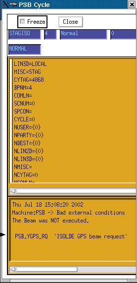
19 Terminology: NORMAL/SPARE(2) Representation in software tools CPS Normal Spare SFTPRO ZERO PSB Normal Spare SFTPRO ISOGPS
20 32 Levels Sequences Level Switch LHC Fill request Fixed Target Lead-In Pulse-Start to 14Gev Main Sequence for Fixed Target Lead-Out Pulse Stop Repeat LHC Fill Lead-In Pulse Start to 26Gev Main Sequence for LHC filling Lead-Out Pulse Stop Sequence Change Lead-in Pulse Start Inject, Ramp Main Coast Lead-out Eject Ramp Pulse Stop
21 External Conditions Comprised of Requests, Inhibits, Interlocks. They are logic levels 1=Bad, 0=Good They control the CBCM Normal <-> Spare Sequence selection BCD termination Can be either hardware or software Used By FIDO (= real time timing command interpretor) to make decisions on what to do next

22 FiDo programs MTG integrates the compiler and the interpreter. Can be downloaded in real-time
23 Beam Coordination Diagram editor

24 Strong Coupling
25 Injection rendezvous points Loose coupling ADE Start point Function points Eject antiprotons Cooling
26 Make MTG table The BCD is the result of the merging of BCDs produces by the two editors. BCD

27 BCD Editor: Rule checker

28 Sequence manager

29 MTG diagnostic

30 CTIM (2)

31 Timing events (CTIM) (3) Controllable by knobs in real-time Virtual event Key events
32 Summary Part 2 The CERN timing system is an almost unique technical solution to a very complex timing/sequencing problem. Only a few accelerator centers in the world are confronted with its complexity of operation. The functionality/hardware implementation has evolved over the past decades. Lots of legacy equipment has still to be supported. Presently a project is under way in order to: - simplify hard- and software - increase functionality (higher resolution, bidirectional information) - name: White Rabbit please visit BE-CO-HT webpages
System: status and evolution. Javier Serrano
 CERN General Machine Timing System: status and evolution Javier Serrano CERN AB-CO-HT 15 February 2008 Outline Motivation Why timing systems at CERN? Types of CERN timing systems. The General Machine Timing
Information here generates the timing configuration and is hence the definitive source. The situation is quite volatile, new events and telegram
 LHC General Machine Timing g( (GMT) Julian Lewis AB/CO/HT Some general points on LHC timing The Basic-Period in the LHC machine is the UTC second. The millisecond modulo represents the millisecond in the
LHC Nominal injection sequence
 LHC Nominal injection sequence Mike Lamont Acknowledgements: Reyes Alemany Fernandez, Brennan Goddard Nominal injection Overall injection scheme Pilot R1, Pilot R2, Intermediate R1 Optimise Intermediate
CERN S PROTON SYNCHROTRON COMPLEX OPERATION TEAMS AND DIAGNOSTICS APPLICATIONS
 Marc Delrieux, CERN, BE/OP/PS CERN S PROTON SYNCHROTRON COMPLEX OPERATION TEAMS AND DIAGNOSTICS APPLICATIONS CERN s Proton Synchrotron (PS) complex How are we involved? Review of some diagnostics applications
Procedures for the Commissioning of the Beam Interlock System for the CNGS and SPS-LHC Transfer Lines
 CERN CH-1211 Geneva 23 Switzerland the Large Hadron Collider project CERN Div./Group or Supplier/Contractor Document No. AB-OP EDMS Document No. 735534 Date: 2006-05-16 Interlock Test Procedure Procedures
Upgrading LHC Luminosity
 1 Upgrading LHC Luminosity 2 Luminosity (cm -2 s -1 ) Present (2011) ~2 x10 33 Beam intensity @ injection (*) Nominal (2015?) 1 x 10 34 1.1 x10 11 Upgraded (2021?) ~5 x10 34 ~2.4 x10 11 (*) protons per
2008 JINST 3 S LHC Machine THE CERN LARGE HADRON COLLIDER: ACCELERATOR AND EXPERIMENTS. Lyndon Evans 1 and Philip Bryant (editors) 2
 2") PUBLISHED BY INSTITUTE OF PHYSICS PUBLISHING AND SISSA RECEIVED: January 14, 2007 REVISED: June 3, 2008 ACCEPTED: June 23, 2008 PUBLISHED: August 14, 2008 THE CERN LARGE HADRON COLLIDER: ACCELERATOR AND
PUBLISHED BY INSTITUTE OF PHYSICS PUBLISHING AND SISSA RECEIVED: January 14, 2007 REVISED: June 3, 2008 ACCEPTED: June 23, 2008 PUBLISHED: August 14, 2008 THE CERN LARGE HADRON COLLIDER: ACCELERATOR AND
1 Digital BPM Systems for Hadron Accelerators
 Digital BPM Systems for Hadron Accelerators Proton Synchrotron 26 GeV 200 m diameter 40 ES BPMs Built in 1959 Booster TT70 East hall CB Trajectory measurement: System architecture Inputs Principles of
Development of an Abort Gap Monitor for High-Energy Proton Rings *
 Development of an Abort Gap Monitor for High-Energy Proton Rings * J.-F. Beche, J. Byrd, S. De Santis, P. Denes, M. Placidi, W. Turner, M. Zolotorev Lawrence Berkeley National Laboratory, Berkeley, USA
Libera Hadron: demonstration at SPS (CERN)
") Creation date: 07.10.2011 Last modification: 14.10.2010 Libera Hadron: demonstration at SPS (CERN) Borut Baričevič, Matjaž Žnidarčič Introduction Libera Hadron has been demonstrated at CERN. The demonstration
Creation date: 07.10.2011 Last modification: 14.10.2010 Libera Hadron: demonstration at SPS (CERN) Borut Baričevič, Matjaž Žnidarčič Introduction Libera Hadron has been demonstrated at CERN. The demonstration
1. General principles for injection of beam into the LHC
 LHC Project Note 287 2002-03-01 Jorg.Wenninger@cern.ch LHC Injection Scenarios Author(s) / Div-Group: R. Schmidt / AC, J. Wenninger / SL-OP Keywords: injection, interlocks, operation, protection Summary
Trigger-timing signal distribution system for the KEK electron/positron injector linac
 Trigger-timing signal distribution system for the KEK electron/positron injector linac T. Suwada, 1 K. Furukawa, N. Kamikubota, and M. Satoh, Accelerator Laboratory, High Energy Accelerator Research Organization
Digital BPMs and Orbit Feedback Systems
 Digital BPMs and Orbit Feedback Systems, M. Böge, M. Dehler, B. Keil, P. Pollet, V. Schlott Outline stability requirements at SLS storage ring digital beam position monitors (DBPM) SLS global fast orbit
North Damping Ring RF
 North Damping Ring RF North Damping Ring RF Outline Overview High Power RF HVPS Klystron & Klystron EPICS controls Cavities & Cavity Feedback SCP diagnostics & displays FACET-specific LLRF LLRF distribution
J-PARC timing system
 J-PARC timing system N.Kamikubota, N.Kikuzawa J-PARC / KEK and JAEA 2015.10.17 at timing workshop Facts in short 1. J-PARC is an accelerator complex located in Ibaraki, Japan 1. Rapid cycle: LI(400MeV
HIGH-INTENSITY PROTON BEAMS AT CERN AND THE SPL STUDY
 HIGH-INTENSITY PROTON BEAMS AT CERN AND THE STUDY E. Métral, M. Benedikt, K. Cornelis, R. Garoby, K. Hanke, A. Lombardi, C. Rossi, F. Ruggiero, M. Vretenar, CERN, Geneva, Switzerland Abstract The construction
LCLS RF Reference and Control R. Akre Last Update Sector 0 RF and Timing Systems
 LCLS RF Reference and Control R. Akre Last Update 5-19-04 Sector 0 RF and Timing Systems The reference system for the RF and timing starts at the 476MHz Master Oscillator, figure 1. Figure 1. Front end
The PEFP 20-MeV Proton Linear Accelerator
 Journal of the Korean Physical Society, Vol. 52, No. 3, March 2008, pp. 721726 Review Articles The PEFP 20-MeV Proton Linear Accelerator Y. S. Cho, H. J. Kwon, J. H. Jang, H. S. Kim, K. T. Seol, D. I.
THE DESIGN OF CSNS INSTRUMENT CONTROL
 THE DESIGN OF CSNS INSTRUMENT CONTROL Jian Zhuang,1,2,3 2,3 2,3 2,3 2,3 2,3, Jiajie Li, Lei HU, Yongxiang Qiu, Lijiang Liao, Ke Zhou 1State Key Laboratory of Particle Detection and Electronics, Beijing,
RF2TTC and QPLL behavior during interruption or switch of the RF-BC source
 RF2TTC and QPLL behavior during interruption or switch of the RF-BC source Study to adapt the BC source choice in RF2TTC during interruption of the RF timing signals Contents I. INTRODUCTION 2 II. QPLL
THE ARCHITECTURE, DESIGN AND REALISATION OF THE LHC BEAM INTERLOCK SYSTEM
 10th ICALEPCS Int. Conf. on Accelerator & Large Expt. Physics Control Systems. Geneva, 10-14 Oct 2005, PO2.031-3 (2005) THE ARCHITECTURE, DESIGN AND REALISATION OF THE LHC BEAM INTERLOCK SYSTEM B. Todd
LHC Beam Instrumentation Further Discussion
 LHC Beam Instrumentation Further Discussion LHC Machine Advisory Committee 9 th December 2005 Rhodri Jones (CERN AB/BDI) Possible Discussion Topics Open Questions Tune measurement base band tune & 50Hz
Status of SOLARIS. Paweł Borowiec On behalf of Solaris Team
 Status of SOLARIS Paweł Borowiec On behalf of Solaris Team e-mail: pawel.borowiec@uj.edu.pl XX ESLS-RF Meeting, Villingen 16-17.11.2016 Outline 1. Timeline 2. Injector 3. Storage ring 16-17.11.2016 XX
WHAT WE WILL DO FOR BEAM PREPARATION IN 2009 : BEAM INTERLOCKS
 WHAT WE WILL DO FOR BEAM PREPARATION IN 2009 : BEAM INTERLOCKS J. Wenninger, CERN, Geneva Abstract A large fraction of the LHC Machine Protection System was commissioned in 2008 in view of the first LHC
First Simultaneous Top-up Operation of Three Different Rings in KEK Injector Linac
 First Simultaneous Top-up Operation of Three Different Rings in KEK Injector Linac Masanori Satoh (Acc. Lab., KEK) for the injector upgrade group 2010/9/16 1 Overview of Linac Beam Operation 2010/9/16
Commissioning of Accelerators. Dr. Marc Munoz (with the help of R. Miyamoto, C. Plostinar and M. Eshraqi)
") Commissioning of Accelerators Dr. Marc Munoz (with the help of R. Miyamoto, C. Plostinar and M. Eshraqi) www.europeanspallationsource.se 6 July, 2017 Contents General points Definition of Commissioning
Commissioning of Accelerators Dr. Marc Munoz (with the help of R. Miyamoto, C. Plostinar and M. Eshraqi) www.europeanspallationsource.se 6 July, 2017 Contents General points Definition of Commissioning
LHC Machine check out
 LHC Machine check out R.Giachino / M.Albert 1v1 Be/op 12th March 2012 Hardware Commissioning: M. Pojer, R. Schmidt and M. Solfaroli Summary of week 10 Machine checkout: R. Giachino, M.Albert and J. Wenninger
FIRST SIMULTANEOUS TOP-UP OPERATION OF THREE DIFFERENT RINGS IN KEK INJECTOR LINAC
 FIRST SIMULTANEOUS TOP-UP OPERATION OF THREE DIFFERENT RINGS IN KEK INJECTOR LINAC M. Satoh #, for the IUC * Accelerator Laboratory, High Energy Accelerator Research Organization (KEK) 1-1 Oho, Tsukuba,
G. Di Pirro, A. Drago, A. Ghigo, F. Sannibale, M. Serio, M. Vescovi TOKEN NAME FAMILY
 K K DAΦNE TECHNICAL NOTE INFN - LNF, Accelerator Division Frascati, February 25, 1997 Note: CD-8 DAΦNE TIMING STATES UPDATE G. Di Pirro, A. Drago, A. Ghigo, F. Sannibale, M. Serio, M. Vescovi The first
Oak Ridge Spallation Neutron Source Proton Power Upgrade Project and Second Target Station Project
 Oak Ridge Spallation Neutron Source Proton Power Upgrade Project and Second Target Station Project Workshop on the future and next generation capabilities of accelerator driven neutron and muon sources
The Elettra Storage Ring and Top-Up Operation
 The Elettra Storage Ring and Top-Up Operation Emanuel Karantzoulis Past and Present Configurations 1994-2007 From 2008 5000 hours /year to the users 2010: Operations transition year Decay mode, 2 GeV (340mA)
Control of Intra-Bunch Vertical Motion in the SPS with GHz Bandwidth Feedback
 Journal of Physics: Conference Series PAPER OPEN ACCESS Control of Intra-Bunch Vertical Motion in the SPS with GHz Bandwidth Feedback To cite this article: J. Fox et al 2018 J. Phys.: Conf. Ser. 1067 072024
New Spill Structure Analysis Tools for the VME Based Data Acquisition System ABLASS at GSI
 New Spill Structure Analysis Tools for the VME Based Data Acquisition System ABLASS at GSI T. Hoffmann, P. Forck, D. A. Liakin * Gesellschaft f. Schwerionenforschung, Planckstr. 1, D-64291 Darmstadt *
Full IEFC workshop Feb.
 How to keep the Injectors running for another 25 years S Baird (on behalf of EN/MEF/ABA) LHC Performance workshop Chamonix How does one keep a 50 51 year old running for another 25 years? accelerator How
A Fast Magnet Current Change Monitor for Machine Protection in HERA and the LHC
 10th ICALEPCS Int. Conf. on Accelerator & Large Expt. Physics Control Systems. Geneva, 10-14 Oct 2005, PO2.042-4 (2005) A Fast Magnet Current Change Monitor for Machine Protection in HERA and the LHC M.Werner
Introduction This application note describes the XTREME-1000E 8VSB Digital Exciter and its applications.
 Application Note DTV Exciter Model Number: Xtreme-1000E Version: 4.0 Date: Sept 27, 2007 Introduction This application note describes the XTREME-1000E Digital Exciter and its applications. Product Description
Klystron Lifetime Management System
 Klystron Lifetime Management System Łukasz Butkowski Vladimir Vogel FLASH Seminar Outline 2 Introduction to KLM Protection and measurement functions Installation at Klystron test stand FPGA implementation
Open loop tracking of radio occultation signals in the lower troposphere
 Open loop tracking of radio occultation signals in the lower troposphere S. Sokolovskiy University Corporation for Atmospheric Research Boulder, CO Refractivity profiles used for simulations (1-3) high
LHC COMMISSIONING PLANS
 LHC COMMISSIONING PLANS R. Alemany Fernández, CERN, Geneva, Switzerland Abstract Operating the Large Hadron Collider (LHC) at design performance is not going to be easy. The machine is complex and with
Features of the 745T-20C: Applications of the 745T-20C: Model 745T-20C 20 Channel Digital Delay Generator
 20 Channel Digital Delay Generator Features of the 745T-20C: 20 Independent delay channels - 100 ps resolution - 25 ps rms jitter - 10 second range Output pulse up to 6 V/50 Ω Independent trigger for every
TRANSVERSE DAMPING AND FAST INSTABILITIES
 TRANSVERSE DAMPING AND FAST INSTABILITIES Abstract The characteristics of the LHC beams in the SPS, protons and ions, pose stringent requirements on the SPS damper (feedback system). The boundary conditions
The basic parameters of the pre-injector are listed in the Table below. 100 MeV
 3.3 The Pre-injector The high design brightness of the SLS requires very high phase space density of the stored electrons, leading to a comparatively short lifetime of the beam in the storage ring. This,
EPJ Web of Conferences 95,
 EPJ Web of Conferences 95, 04012 (2015) DOI: 10.1051/ epjconf/ 20159504012 C Owned by the authors, published by EDP Sciences, 2015 The ELENA (Extra Low Energy Antiproton) project is a small size (30.4
Sérgio Rodrigo Marques
 Sérgio Rodrigo Marques (on behalf of the beam diagnostics group) sergio@lnls.br Outline Introduction Stability Requirements General System Requirements FOFB Strategy Hardware Overview Performance Tests:
Status of the X-ray FEL control system at SPring-8
 Status of the X-ray FEL control system at SPring-8 T.Fukui 1, T.Hirono 2, N.Hosoda 1, M.Ishii 2, M.Kitamura 1 H.Maesaka 1,T.Masuda 2, T.Matsushita 2, T.Ohata 2, Y.Otake 1, K.Shirasawa 1,M.Takeuchi 2, R.Tanaka
CMS Tracker Synchronization
 CMS Tracker Synchronization K. Gill CERN EP/CME B. Trocme, L. Mirabito Institut de Physique Nucleaire de Lyon Outline Timing issues in CMS Tracker Synchronization method Relative synchronization Synchronization
Linac 4 Instrumentation K.Hanke CERN
 Linac 4 Instrumentation K.Hanke CERN CERN Linac 4 PS2 (2016?) SPL (2015?) Linac4 (2012) Linac4 will first inject into the PSB and then can be the first element of a new LHC injector chain. It will increase
CMS Conference Report
 Available on CMS information server CMS CR 1997/017 CMS Conference Report 22 October 1997 Updated in 30 March 1998 Trigger synchronisation circuits in CMS J. Varela * 1, L. Berger 2, R. Nóbrega 3, A. Pierce
Present Status and Future Upgrade of KEKB Injector Linac
 Present Status and Future Upgrade of KEKB Injector Linac Kazuro Furukawa, for e /e + Linac Group Present Status Upgrade in the Near Future R&D towards SuperKEKB 1 Machine Features Present Status and Future
A HIGH-POWER SUPERCONDUCTING H - LINAC (SPL) AT CERN
 AT CERN") A HIGH-POWER SUPERCONDUCTING H - LINAC (SPL) AT CERN E. Chiaveri, CERN, Geneva, Switzerland Abstract The conceptual design of a superconducting H - linear accelerator at CERN for a beam energy of 2.2 GeV
A HIGH-POWER SUPERCONDUCTING H - LINAC (SPL) AT CERN E. Chiaveri, CERN, Geneva, Switzerland Abstract The conceptual design of a superconducting H - linear accelerator at CERN for a beam energy of 2.2 GeV
THE ANTIPROTON DECELERATOR (AD)
") EUROPEAN ORGANIZATION FOR NUCLEAR RESEARCH CERN - PS DIVISION CERN/PS 99-50 (HP) THE ANTIPROTON DECELERATOR (AD) S. Maury (on behalf of the AD team) Abstract To continue an important part of the LEAR physics
EUROPEAN ORGANIZATION FOR NUCLEAR RESEARCH CERN - PS DIVISION CERN/PS 99-50 (HP) THE ANTIPROTON DECELERATOR (AD) S. Maury (on behalf of the AD team) Abstract To continue an important part of the LEAR physics
RF PERFORMANCE AND OPERATIONAL ISSUES
 RF PERFORMANCE AND OPERATIONAL ISSUES A. Butterworth, L. Arnaudon, P. Baudrenghien, O. Brunner, E. Ciapala, W. Hofle, J. Molendijk, CERN, Geneva, Switzerland Abstract During the 2009 LHC run, a number
Detailed Design Report
 Detailed Design Report Chapter 4 MAX IV Injector 4.6. Acceleration MAX IV Facility CHAPTER 4.6. ACCELERATION 1(10) 4.6. Acceleration 4.6. Acceleration...2 4.6.1. RF Units... 2 4.6.2. Accelerator Units...
ANKA RF System - Upgrade Strategies
 ANKA RF System - Upgrade Strategies Vitali Judin ANKA Synchrotron Radiation Facility 2014-09 - 17 KIT University of the State Baden-Wuerttemberg and National Laboratory of the Helmholtz Association www.kit.edu
An Overview of Beam Diagnostic and Control Systems for AREAL Linac
 An Overview of Beam Diagnostic and Control Systems for AREAL Linac Presenter G. Amatuni Ultrafast Beams and Applications 04-07 July 2017, CANDLE, Armenia Contents: 1. Current status of existing diagnostic
The high-end network analyzers from Rohde & Schwarz now include an option for pulse profile measurements plus, the new R&S ZVA 40 covers the
 GENERAL PURPOSE 44 448 The high-end network analyzers from Rohde & Schwarz now include an option for pulse profile measurements plus, the new R&S ZVA 4 covers the frequency range up to 4 GHz. News from
PEP-I1 RF Feedback System Simulation
 SLAC-PUB-10378 PEP-I1 RF Feedback System Simulation Richard Tighe SLAC A model containing the fundamental impedance of the PEP- = I1 cavity along with the longitudinal beam dynamics and feedback system
G0 Laser Status Parity Controls Injector Diagnostics
 G0 Laser Status Parity Controls Injector Diagnostics G0 Collaboration Mtg Jefferson Lab August 16, 2002 G0 Collaboration Mtg (August 16, 2002), 1 Installed new AOM homebuilt laser G0 Collaboration Mtg
CONTROL OF THE LOW LEVEL RF SYSTEM OF THE LARGE HADRON COLLIDER
 10th ICALEPCS Int. Conf. on Accelerator & Large Expt. Physics Control Systems. Geneva, 10-14 Oct 2005, PO1.028-1 (2005) CONTROL OF THE LOW LEVEL RF SYSTEM OF THE LARGE HADRON COLLIDER A. Butterworth 1,
Bunch-by-bunch feedback and LLRF at ELSA
 Bunch-by-bunch feedback and LLRF at ELSA Dmitry Teytelman Dimtel, Inc., San Jose, CA, USA February 9, 2010 Outline 1 Feedback Feedback basics Coupled-bunch instabilities and feedback Beam and feedback
report L.M. Fraile, CERN PH/IS Impact of technical issues Running statistics 2006 Planning for 2007
 ISOLDE ISOLDE scientific scientific coordinator s s report report ISOLDE ISOLDE Collaboration Collaboration Committee, Committee, 15 15 February February 2007 2007 L.M. Fraile, CERN PH/IS Impact of technical
Equipment Installation, Planning, Layout, organisation and updates
 Equipment Installation, Planning, Layout, organisation and updates Simon Mataguez, Julie Coupard with contributions of the LIU-PLI team Table of contents: LIU installation activities Organisation of the
30 GHz Power Production / Beam Line
 30 GHz Power Production / Beam Line Motivation & Requirements Layout Power mode operation vs. nominal parameters Beam optics Achieved performance Problems Beam phase switch for 30 GHz pulse compression
Characterizing Transverse Beam Dynamics at the APS Storage Ring Using a Dual-Sweep Streak Camera
 Characterizing Transverse Beam Dynamics at the APS Storage Ring Using a Dual-Sweep Streak Camera Bingxin Yang, Alex H. Lumpkin, Katherine Harkay, Louis Emery, Michael Borland, and Frank Lenkszus Advanced
SUMMARY OF SESSION 4 - UPGRADE SCENARIO 2
 Published by CERN in the Proceedings of RLIUP: Review of LHC and Injector Upgrade Plans, Centre de Convention, Archamps, France, 29 31 October 2013, edited by B. Goddard and F. Zimmermann, CERN 2014 006
Fast Orbit Feedback at the SLS. Outline
 Fast Orbit Feedback at the SLS 2nd Workshop on Beam Orbit Stabilisation (December4-6, 2002, SPring-8) T. Schilcher Outline Noise Sources at SLS Stability / System Requirements Fast Orbit Feedback Implementation
Development of beam-collision feedback systems for future lepton colliders. John Adams Institute for Accelerator Science, Oxford University
 Development of beam-collision feedback systems for future lepton colliders P.N. Burrows 1 John Adams Institute for Accelerator Science, Oxford University Denys Wilkinson Building, Keble Rd, Oxford, OX1
Position Resolution of Optical Fibre-Based Beam Loss Monitors using long electron pulses
 Position Resolution of Optical Fibre-Based Beam Loss Monitors using long electron pulses E. Nebot del Busto (1,2, 3), M. J. Boland (4,5), S. Doebert (1), F. S. Domingues (1), E. Effinger (1), W. Farabolini
STATUS AND CONCEPTUAL DESIGN OF THE CONTROL SYSTEM FOR THE HEAVY ION THERAPY ACCELERATOR FACILITY HICAT
 10th ICALEPCS Int. Conf. on Accelerator & Large Expt. Physics Control Systems. Geneva, 10-14 Oct 2005, PO1.025-1 (2005) STATUS AND CONCEPTUAL DESIGN OF THE CONTROL SYSTEM FOR THE HEAVY ION THERAPY ACCELERATOR
Figure 30.1a Timing diagram of the divide by 60 minutes/seconds counter
 Digital Clock The timing diagram figure 30.1a shows the time interval t 6 to t 11 and t 19 to t 21. At time interval t 9 the units counter counts to 1001 (9) which is the terminal count of the 74x160 decade
Workshop on Accelerator Operations August 6-10, 2012 Glen D. Johns Accelerator Operations Manager
 HWDB: Operations at the Spallation Neutron Source Workshop on Accelerator Operations August 6-10, 2012 Glen D. Johns Accelerator Operations Manager Outline Facility overview Organization Shift schedule
GFT Channel Digital Delay Generator
 Features 20 independent delay Channels 100 ps resolution 25 ps rms jitter 10 second range Output pulse up to 6 V/50 Ω Independent trigger for every channel Fours Triggers Three are repetitive from three
5 Project Costs and Schedule
 93 5 Project Costs and Schedule 5.1 Overview The cost evaluation for the integrated version of the XFEL with 30 experiments and 35 GeV beam energy as described in the TDR-2001 yielded 673 million EUR for
PEP II Design Outline
 PEP II Design Outline Balša Terzić Jefferson Lab Collider Review Retreat, February 24, 2010 Outline General Information Parameter list (and evolution), initial design, upgrades Collider Ring Layout, insertions,
Sequential circuits. Same input can produce different output. Logic circuit. William Sandqvist
 Sequential circuits Same input can produce different output Logic circuit If the same input may produce different output signal, we have a sequential logic circuit. It must then have an internal memory
TV Synchronism Generation with PIC Microcontroller
 TV Synchronism Generation with PIC Microcontroller With the widespread conversion of the TV transmission and coding standards, from the early analog (NTSC, PAL, SECAM) systems to the modern digital formats
ANKA Status Report. N.Smale, A.-S. Müller, E. Huttel, M.Schuh Slides courtesy of A.-S. Müller and C.Heske.
 ANKA Status Report N.Smale, A.-S. Müller, E. Huttel, M.Schuh Slides courtesy of A.-S. Müller and C.Heske. KIT - University of the State of Baden-Wuerttemberg and National Laboratory of the Helmholtz Association
CLIC Feasibility Demonstration at CTF3
 CLIC Feasibility Demonstration at CTF3 Roger Ruber Uppsala University, Sweden, for the CLIC/CTF3 Collaboration http://cern.ch/clic-study LINAC 10 MO303 13 Sep 2010 The Key to CLIC Efficiency NC Linac for
CLEX (CLIC Experimental Area)
") CLEX (CLIC Experimental Area) Status and plans G.Geschonke for Hans Braun CERN CT3 coll meetg 2005 CLEX 1 CT3 objectives R1.1 CLIC accelerating structure, R1.2 rive beam scheme with a fully loaded linac
CLEX (CLIC Experimental Area) Status and plans G.Geschonke for Hans Braun CERN CT3 coll meetg 2005 CLEX 1 CT3 objectives R1.1 CLIC accelerating structure, R1.2 rive beam scheme with a fully loaded linac
Simple motion control implementation
 Simple motion control implementation with Omron PLC SCOPE In todays challenging economical environment and highly competitive global market, manufacturers need to get the most of their automation equipment
Field Programmable Gate Array (FPGA) Based Trigger System for the Klystron Department. Darius Gray
 Based Trigger System for the Klystron Department. Darius Gray") SLAC-TN-10-007 Field Programmable Gate Array (FPGA) Based Trigger System for the Klystron Department Darius Gray Office of Science, Science Undergraduate Laboratory Internship Program Texas A&M University,
SLAC-TN-10-007 Field Programmable Gate Array (FPGA) Based Trigger System for the Klystron Department Darius Gray Office of Science, Science Undergraduate Laboratory Internship Program Texas A&M University,
CBF500 High resolution Streak camera
 High resolution Streak camera Features 400 900 nm spectral sensitivity 5 ps impulse response 10 ps trigger jitter Trigger external or command 5 to 50 ns analysis duration 1024 x 1024, 12-bit readout camera
GFT Channel Slave Generator
 GFT1018 8 Channel Slave Generator Features 8 independent delay channels 1 ps time resolution < 100 ps rms jitter for optical triggered delays 1 second range Electrical or optical output Three trigger modes
P. Adamson, Fermi National Accelerator Laboratory, Batavia, IL 60510, USA. Abstract
 Abstract 7 0 0 k W M A I N I N J E C T O R O P E R A T I O N S F O R N O νa AT FNAL P. Adamson, Fermi National Accelerator Laboratory, Batavia, IL 60510, USA Following a successful career as an antiproton
Registers and Counters
 Registers and Counters Clocked sequential circuit = F/Fs and combinational gates Register Group of flip-flops (share a common clock and capable of storing one bit of information) Consist of a group of
PEP-II Overview & Ramp Down Plan. J. Seeman DOE PEP-II Ramp Down-D&D Review August 6-7, 2007
 PEP-II Overview & Ramp Down Plan J. Seeman DOE PEP-II Ramp Down-D&D Review August 6-7, 2007 Topics Overview of the PEP-II Collider PEP-II turns off September 30, 2008. General list of components and buildings
COMMISSIONING OF THE ALBA FAST ORBIT FEEDBACK SYSTEM
 COMMISSIONING OF THE ALBA FAST ORBIT FEEDBACK SYSTEM A. Olmos, J. Moldes, R. Petrocelli, Z. Martí, D. Yepez, S. Blanch, X. Serra, G. Cuni, S. Rubio, ALBA-CELLS, Barcelona, Spain Abstract The ALBA Fast
P. Emma, et al. LCLS Operations Lectures
 P. Emma, et al. LCLS Operations Lectures LCLS 1 LCLS Accelerator Schematic 6 MeV 135 MeV 250 MeV σ z 0.83 mm σ z 0.83 mm σ z 0.19 mm σ δ 0.05 % σ δ 0.10 % σ δ 1.6 % Linac-0 L =6 m rf gun L0-a,b Linac-1
VGA Port. Chapter 5. Pin 5 Pin 10. Pin 1. Pin 6. Pin 11. Pin 15. DB15 VGA Connector (front view) DB15 Connector. Red (R12) Green (T12) Blue (R11)
 DB15 Connector. Red (R12) Green (T12) Blue (R11)") Chapter 5 VGA Port The Spartan-3 Starter Kit board includes a VGA display port and DB15 connector, indicated as 5 in Figure 1-2. Connect this port directly to most PC monitors or flat-panel LCD displays
Chapter 5 VGA Port The Spartan-3 Starter Kit board includes a VGA display port and DB15 connector, indicated as 5 in Figure 1-2. Connect this port directly to most PC monitors or flat-panel LCD displays
Status of CTF3. G.Geschonke CERN, AB
 Status of CTF3 G.Geschonke CERN, AB CTF3 layout CTF3 - Test of Drive Beam Generation, Acceleration & RF Multiplication by a factor 10 Drive Beam Injector ~ 50 m 3.5 A - 2100 b of 2.33 nc 150 MeV - 1.4
COMMISSIONING SCENARIOS FOR THE J-PARC ACCELERATOR COMPLEX
 COMMISSIONING SCENARIOS FOR THE J-PARC ACCELERATOR COMPLEX T. Koseki, M. Ikegami, M. Tomizawa, Accelerator Laboratory, KEK, Tsukuba, Japan F. Noda, JAEA, Tokai, Japan Abstract The J-PARC (Japan Proton
Assembly of the HIE-ISOLDE accelerator cavities in a clean room.
 Final adjustments being made in the LHC tunnel before the return of beams. On 5 April, particles began circulating in the accelerator for the first time following the Long Shutdown. (CERN-PHOTO-201503-058-1)
Radiation Safety System for Stanford Synchrotron Radiation Laboratory*
 SLAC PUB-8817 April 16, 2001 Radiation Safety System for Stanford Synchrotron Radiation Laboratory* James C. Liu, N. E. Ipe and R. Yotam Stanford Linear Accelerator Center, P. O. Box 4349, Stanford, CA
Chapter 4. Logic Design
 Chapter 4 Logic Design 4.1 Introduction. In previous Chapter we studied gates and combinational circuits, which made by gates (AND, OR, NOT etc.). That can be represented by circuit diagram, truth table
EUROFEL-Report-2007-DS EUROPEAN FEL Design Study
 EUROFEL-Report-2007-DS4-095 EUROPEAN FEL Design Study Deliverable N : D 4.3 Deliverable Title: Task: Authors: Generation of 3rd harmonic photons at 90 nm DS-4 see next page Contract N : 011935 Project
BABAR IFR TDC Board (ITB): requirements and system description
: requirements and system description") BABAR IFR TDC Board (ITB): requirements and system description Version 1.1 November 1997 G. Crosetti, S. Minutoli, E. Robutti I.N.F.N. Genova 1. Timing measurement with the IFR Accurate track reconstruction
BABAR IFR TDC Board (ITB): requirements and system description Version 1.1 November 1997 G. Crosetti, S. Minutoli, E. Robutti I.N.F.N. Genova 1. Timing measurement with the IFR Accurate track reconstruction
Proton Engineering Frontier Project
 Proton Engineering Frontier Project OECD Nuclear Energy Agency Fifth International Workshop on the Utilisation and Reliability of High Power Proton Accelerators (HPPA5) (6-9 May 2007, Mol, Belgium) Yong-Sub
ATSC vs NTSC Spectrum. ATSC 8VSB Data Framing
 ATSC vs NTSC Spectrum ATSC 8VSB Data Framing 22 ATSC 8VSB Data Segment ATSC 8VSB Data Field 23 ATSC 8VSB (AM) Modulated Baseband ATSC 8VSB Pre-Filtered Spectrum 24 ATSC 8VSB Nyquist Filtered Spectrum ATSC
TITLE PAGE. Title of paper: PUSH-PULL FEL, A NEW ERL CONCEPT Author: Andrew Hutton. Author Affiliation: Jefferson Lab. Requested Proceedings:
 TITLE PAGE Title of paper: PUSH-PULL FEL, A NEW ERL CONCEPT Author: Andrew Hutton Author Affiliation: Jefferson Lab Requested Proceedings: Unique Session ID: Classification Codes: Keywords: Energy Recovery,
USER INTERFACE TO THE BEAM INTERLOCK SYSTEM
 Document No. CERN AB DEPARTMENT CH-1211 Geneva 23 Switzerland CERN Div./Group or Supplier/Contractor Document No AB/CO/MI EDMS Document No. 636589 Date: 16 OCTOBER 2006 TECHNICAL NOTE USER INTERFACE TO