Photocathode activity for. P. Michelato
|
|
|
- Oliver Adams
- 5 years ago
- Views:
Transcription
1 Photocathode activity for FLASH and PITZ P. Michelato INFN Milano LASA
2 Our Production at glance 5 Oct 6 49 Cs Te (37+1) KCsTe ( + ) 5 Mo (11+14)
3 Main Topics Preparation System Plug Preparation Photocathode Deposition Photocathode th Diagnostics After Use Analysis R&D


4 Preparation System Transport Box Preparation Chamber UHV Vacuum System (base pressure 1-1 mbar) 6 sources slot available Te sources out of % pure element Cs sources from SAES High pressure Hg lamp and interference filter for online monitoring of QE during production Masking system 5 x UHV transport box Source holder and Masking Masking MaskingSystem
5 Mo Plug Preparation The Mo plugs, after proper machining to design specifications with either a lathing or a milling machine, are cleaned with a Buffered Chemical Polishing. The plugs are then polished to optical finishing with two different procedures: Manual Silicon Carbide based abrasive papers Different clothes with diamond suspensions spensions (3μm.1μm) Automatic Special paper ( diamond embedded disc ) with diamond suspension (6μm) Different clothes with diamond suspensions (3μm.1μm) The automatic procedure ensures planar photocathode surfaces. Sintered Arc-cast 7 Before and After Optical Polishing 8
. The two polishing techniques on plugs for Cs Te cathodes give similar reflectivity values.")

6 Plug Roughness and Dark Current The main advantage of the optical finishing of the photocathodes is the reduced dark current (one order of magnitude). The two polishing techniques on plugs for Cs Te cathodes give similar reflectivity values. Rough Surface Optical Finished No significant reflectivity difference between Arc-cast and sintered Mo..736 μm 1 8 Mo 543 nm ArcCast R = % Sintered R = % Reflectivity [%]


7 Cs Te Photocathode Deposition Cs Te Mo Cs/Te b).6 c) 1. d) 1.9 e).5 Different stoichiometric compounds form during Cs deposition till the correct Cs/Te ratio is reached corresponding to the QE maximum. The Mo plug prevents diffusion of the film. Estimated photocathode typical thickness is -3 nm. A circular masking system shapes the photoemissive layer and center it on the plug. The actual masking diameter is 5 mm. Active Area A. di Bona et al., JAP8(1996)34-13 mm -1 mm - 5 mm 5 mm
8 Photocathode Diagnostics QE 54 nm We check routinely : QE and QE uniformity Color and color uniformity Spectral response (QE vs. Photon Energy) Contour 1, 1, 1 Spectral Response Normalized QE,8,6,4,, 4 X Axis (mm) Y axis (mm) 1 QE [%] TTF&PITZ Laser λ =6 nm.1.1 Experimental Data Photon Enegy [ev]
9 MultiWavelengths QE maps 39 nm 54 nm 97 nm QE map: nm of cathode #73.1 (4-3-4), +/-4mm, step.5mm QE map:73-1i(54nm) of cathode #73.1 (3-3-4), +/-4mm, step.5mm QE map: nm of cathode #73.1 (4-3-4), +/-5mm, step.5mm The MultiWavelength Maps allow to check the cathode uniformity. Moreover since: QE (E ph -(E g +E a )) m nm QE map: nm of cathode #73.1 (3-3-4), +/-5mm, step.5mm where E ph is the photon energy, E g the energy gap and E a the electron affinity, we might calculate the E g +E a of the photocathode. This parameter influences the emission properties, the darkcurrent and the thermal emittance nm QE map: nm of cathode #73.1 (3-3-4), +/-5mm, step.5mm
10 E g +E a map Molybdenum E g +E a Cs Te The cathode show a clear region of low E g+e a in correspondence with the photoemissive film. Irregularities in the map can be correlated to region of unexpected behaviour of the cathode
11 Color Evolution during preparation We are interested to film colors and their uniformities a) h) since they carry information on film optical properties and thickness. Pictures show the evolution of the film during the different phases of the photocathode growing process. h) e) After 1 min of Te deposition (end of Te deposition) From further analysis, we expect information on the optical properties and thickness of the photoemissive film. After 45 min of Cs deposition After 65 min of Cs deposition (cathode finished)
12 Color Uniformity Investigation A Puzzle
13 QE LASA DC QE LASA before and after use at FLASH or PITZ.
14 QE FLASH/PITZ not recently updated d Pulsed QE FLASH/PITZ.
15 43. QE Statistics 14 1 QE = 9.19%+ 3.4% Photocathode QE distribution for the samples sent to FLASH and PITZ Samples QE [%] Different cathodes produced on the same plug QE [%] 8 6 4
16 After Transportation Analysis Cathode 1. was produced in year. 1 8 It was delivered and stored in the transport box for 3 years without being used in any gun. After such long period, it was measured at LASA showing good uniformity in color and QE, and QE values similar to the ones after production QE map after production Optical image of the cathode after 3 years QE map after 3 years


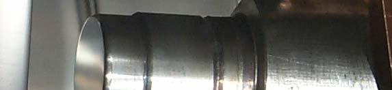
17 Operation Effect on Plugs We have observed damages on the plug of used cathodes. The damages are located in the spring region of the plug. Sputtered material are clearly visible. Cathode #8.1 Cathode #47.3


")

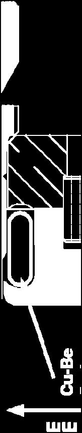
18 RF spring contact Two different spring types have been used, in the same insert! The insert was designed for a WELDED Watch bend type spring. Watch bend tipe CuBe hard, silver coated spring Difficult to weld (becomes hard) Critical number of convolutions Cantend coil spring CuBe uncoated. Available coated with Ag, Au etc Welded by the manufacturer
19 Spring, a dark current source? Pictures taken at PITZ, PITZ in the same condition of gradient and focalization, of Mo (up, #56.) and CsTe (down, #54.) cathodes. The images g looks similar except p for the inner ring! g We observe: Three circular regions of different intensities Clear flares are visible #56. (Mo) The flares spirals from the center outwards due to the large energy spread of the emitted electrons traveling in the solenoid magnetic fields. The flares seem to originate from the outer and middle rings. The outer flares have been attributed, in the past, to dark current coming from the region between the plug and the gun body, where the RF contact spring is located. #54 (C #54. (CsTe) T )
20 Dark current investigation We developed a simple computational model to reproduce the dark current patterns at the screen position particles generated only on the plug border 5 azymuthal angles, in order to mimic the spring convolutions (~8 in the present design). Increasing the number of azymuthal positions results in a more defined outer ring image. the main features of the images are reproduced the plug border region, where the RF spring is located, could be responsible of the dark current emission. as previous case plus one hot spot of electrons to artificially enhanced the distribution. two bright spots are visible and a light blue flare crosses the whole image. Since many particles have been used for the hot spot generation, the underlining structure is fainter then before
21 R&D on Photocathodes Optical Properties Thermal Emittance Photoemission Model DC Gun Test Stand
22 Cs Te Optical Properties 1 Vacuum.8 ivity.6 Thin Film Cs Te Reflecti.4 R S Substrate Mo. S. Bettoni, Thesis R P Incidence Angle [ ] n k σ [nm] Thickness [nm] σ = roughness parameter From the depth profile we measured about 3 nm Mo Mo+Te Mo+Cs Te
,,4,6,8 1 1, energy (ev) 1 3 4 5 6 7 8 7 Angle Integrated Electron velocity distribution resolved in angle and")
 5 th harmonic (λ = 11 nm) ε th = 7.")
23 a. u. Thermal Emittance by TOF Angle resolved photoemission spectra θ Raw Spectra V=.45V (sn),,4,6,8 1 1, energy (ev) Angle Integrated Electron velocity distribution resolved in angle and energy imation (mm mrad) The ermal Emittance Esti th harmonic (λ = 64 nm) ε th =.5 ±.1 mm mrad for 1 mm rms spot radius 5 4 th th harmonic 45 th th harmonic Bias Voltage (V) 5 th harmonic (λ = 11 nm) ε th = 7.7 ± 1.1 mm mrad for 1 mm rms spot radius


24 Vacuum Modello della fotoemissione di Spicer Photoemission Model This model is based on a simple implementation of Spicer s Three Step Model I Vacuum Vacuum This model, once developed and I R test, will be used to study CsTe spectra and estimate thermal emittance and key parameters Sample Sample Sample
25 DC Gun Test Stand Dark current test Field enhanced photoemission Transfer System HV Extractor
26 Conclusions The photocathodes produced so far have performed as requested. An R&D activity it is in progress to both investigate sources of dark current and reduce them. An improvement of the reproducibility is required.
 L.")

27 Photocathode FLASH: Quantum Efficiency (QE) L. Monaco Work supported by the European Community (contract number RII3-CT-4-568)
28 Main Topics Overview Photocathode Production Production at LASA and transportation The Photocathode Database CW QE measurements (Hg lamp) Experimental set-up Results of measurements at FLASH Pulsed QE measurements Laser energy calibration Measurements on different cathodes Results QE maps Conclusions
29 Quantum Efficiency For the FLASH laser (λ = 6nm) QE(%).5*Q(nC)/E(µJ) The design asks for 7 nc/s QE required for FLASH: >.5 % to keep the laser in a reasonable limit: within an average power of ~W Design of present laser accounts for QE=.5% with an overhead of a factor of 4 and has an average power of W (IR) Cs Te cathodes found to be the best choice


30 Photocathode Production: Preparation Chamber Photocathodes are LASA on Mo plugs under UHV condition. Transport Box Source holder Preparation LASA Masking UHV Vacuum System - base pressure 1-1 mbar 6 sources slot available Te sources out of % pure element Cs sources from SAES High pressure Hg lamp and interference filter for online monitoring of QE during production Masking system 5 x UHV transport box Mo Plug Masking
31 Production: diagnostic on photocathodes The photoemissive properties of produced cathodes are checked performing spectral response measurements and QE maps (also at different wavelengths). QE 54nm (Hg lamp, interferential filter, 1mm spot diameter) QE map:73-1i(54nm) of cathode #73.1 (3-3-4) 4), +/-4mm /4mm, step.5mm 8 1.E+ 1.E+1 1.E+ Spectral response 6 (Hg lamp, interferential filters, 5 4 3mm spot diameter) QE (%) 1.E-1 1.E- 1.E-3 Just after the deposition QE map:73-1i(54nm) of cathode #73.1 (3-3-4), +/-4mm, step.5mm E Photon Energy (ev) d=5mm


32 Production: from LASA to FLASH and PITZ Transport box Produced cathodes, are loaded in the transport box and shipped to FLASH or PITZ keeping the UHV condition. The box is then connected to the RF gun. Since 1998, we have shipped to TTF phase I, FLASH and PITZ: 49 x Cs Te x KCsTe 5 x Mo Total transfers from LASA: 5 RF gun and FLASH linac

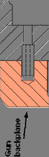
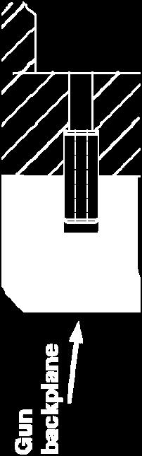


33 Cathode in the RF Gun Photocathode inserted into the gun backplane


 and")


34 Production:The Photocathode Database Many of the data relative to photocathodes (production, operation, lifetimes) and transport box are stored in the photocathode database whose WEB-interface is available at: The database keeps track of the photocathodes in the different transport boxes and in the different labs (TTF, PITZ and LASA).
 Picoammeter Power energy meter cathodes towards the exchange chamber cathode carrier 1.")
35 CW QE measurements: Experimental setup The experimental set-up for the CW QE measurements is mainly composed by: towards the RF gun A high pressure Hg lamp Interferential filters (39nm, 54nm, 97nm, 334nm) Picoammeter Power energy meter cathodes towards the exchange chamber cathode carrier 1. na 3 V picoammeter neutral density filters interferential filter lens Hg lamp Neutral density filters Optical components (1 lens, 1 mirror, pin-holes) transport box anode viewport pin-hole power head n W power meter condenser pin-hole
36 CW QE measurements: Results DESY on March 31 6 Data have been fitted to evaluate: the 6nm and Eg+Ea Cathode Dep. data QE@54nm Operation QE@54nm QE@6nm Eg+Ea (LASA) lifetimes (DESY) (DESY) (ev) Mar-5 7.9% %.79% Mar-5 9.% %.33% Sep-4 7.% 161.%.15% Cathode 73.1 Cathode 7.1 Cathode Cathode Eg+Ea =4.1654eV - QE (@6 nm) =.7873% - Slope = Experimental Fit QE (@6 nm) =.79% 1 Cathode Eg+Ea =4.168eV - QE (@6 nm) =.3676% - Slope = QE (@6 nm) =.33% Cathode 3. - Eg+Ea =4.157eV - QE (@6 nm) =.15369% - Slope = Experimental Fit 1-1 QE (@6 nm) =.15% QE [%] 1-1 QE [%] QE [%] Experimental Fit photon energy [ev] photon energy [ev] photon energy [ev]
37 CW QE measurements: Data Analysis CW data analysis Fitting of the spectral response = A [ h ν ( E E ) ] m QE E G + E A where A is a constant, E G and E A are energy gap and electron affinity. 1 1 Cathode Eg+Ea =4.1654eV - QE (@6 nm) =.7873% - Slope =1.417 QE [%] Experimental Fit QE (@6 nm) =.79% An example is given for the analysis of the CW QE data for cathode In this case: 1 - Eg+Ea = ev Cathode # photon energy [ev]
38 CW QE measurements: Data Analysis 1 1 QE (%) 1.1 Just after.1 the deposition Photon energy (ev) 1.E+ Powel (*) 1.E+1 QE (%) 1.E+ 1.E-1 1.E- 1.E-3 1.E-4 just after the deposition after 61h and 55min after 114h and 4min after 46 and min (*)R. A. Powell, W. E. Spicer, G. B. Fisher, P. Gregory, Photoemission studies of cesium telluride, PRB 8 (9), p (1973) A fresh cathode shows a Eg+Ea of about 3.5 ev. Several measurements of the spectral response have been performed to study the Eg+Ea increase vs. time. 1.E Photon Energy (ev)

 and different energies.")
, varying the laser energy using the")
39 Pulsed QE measurements: laser energy calibration experimental set-up λ/ plate polarizer movable mirror The laser energy transmission (from the laser hut to the tunnel) has been evaluated for different iris diameters (3.5mm,.mm and.16mm) and different energies. Joulemeter mirror The laser energy has been measured using a Pyroelectric gauge (Joulemeter), varying the laser energy using the variable attenuator (λ/ wave plate + polarizer).


![5 4 6 8 1 Attenuator Step Laser room / tunnel Mean trasnmission:14.1868 [%]above4steps.](/docs-images/87/96377702/images/40-2.jpg "15 O:\TESLA\TTF\QE\energy calibration\cal-pyro-3136_1651iris.txt Mean trasnmission:17.178 [%]above4steps.5.18 Tunnel.")
![4 sin fit.175 Energy [μj].3..1 4 6 8 1 Attenuator Step nel) sin (Laser room) / sin (tun.145.14.135.](/docs-images/87/96377702/images/40-3.jpg "13 4 6 8 1 Attenuator Step.17.165.16 iris i =1651.")
40 Pulsed QE measurements: laser beamline transmission analysis The QE measurement procedure uses the laser energy measured on the laser table Transmission to the vacuum window is regularly measured Transmission of the vacuum window (9 %) and reflectivity i of the vacuum laser mirror (9 %) are accounted for iris = 3.5 mm as an example: O:\TESLA\TTF\QE\31-3-6\6-3-31T1493-QE.dat.5 Laser Room sin fit Energy [μj] Attenuator Step Laser room / tunnel Mean trasnmission: [%]above4steps.15 O:\TESLA\TTF\QE\energy calibration\cal-pyro-3136_1651iris.txt Mean trasnmission: [%]above4steps.5.18 Tunnel.4 sin fit.175 Energy [μj] Attenuator Step nel) sin (Laser room) / sin (tun Attenuator Step iris i = Attenuator Step Laser energy is measured as a function of the variable attenuator setting fitted by sin to evaluate the transmission Iris = 3.5 mm Iris =. mm Iris =.16 mm (σ)
41 Pulsed QE measurements: laser beam line transmission measurements The laser beamline transmission has been evaluated four times (from March to August 6) to take care of changes in the optical transmission path. Iris Φ (mm) Iris (motor Date (tunnel Date (laser room Transmission Used steps) file) file) Mar-6 1-Mar % From 1 March Mar-6 1-Mar % to 31 March not done not done Mar-6 31-Mar % From 31 March Mar-6 31-Mar % to 6 June Mar-6 31-Mar-6.85% not done not done - From 6 June to June-6 6-June % 7 Aug not done not done not done not done - From 7 August Aug-6 7-Aug % till now not done not done -
42 Pulsed QE measurements: measurement analysis The QE measurement is done following this procedure: 1. Measurement of the charge (toroid T1, Q[C]).Measurement of the laser energy (laser hut) E 3.Calculation of the laser energy on the cathode E cath [J] using transmission i (considering i the losses due to the vacuum window and mirror) 3 [ ] QE % = nel nph 1 = [ ] Eph[ ev] E [ J] Q C cath 1 6 nm: QE(%).5*Q(nC)/E(µJ) QE =3.1% O:\TESLA\TTF\QE\14-3-6\6-3-14T QE.dat.5 The QE value is then obtained fitting the charge low charge to be sure not to be affected by the space charge Charg ge (nc) space charge effect The relative and systematic errors are in the order of % Laser Energy (uj) The systematic error is mainly due to the uncertainty of identifying the linear part for the fit and due to the transmission measurement uncertainty
43 Pulsed QE measurements: cathode lifetime 6 QE of cathodes are measured frequently within months. Example: cathode 7.1 and We define the end of lifetime when the QE reaches.5 % The CW QE of cathode 73.1 is compared with the pulsed QE measured the same day. The difference may be explained considering the increase of the charge due to the field enhancement. All cathodes show a drop of the QE over time,,with different characteristics. E (%) Q %) QE ( End of lifetime QE <.5% 14-Nov-5 14-Dec-5 13-Jan date End of lifetime QE <.5% 7.1 mean 7.1 CW_7.1 1-Feb-6 14-Mar-6 13-Apr mean 73.1 CW_ Mar-6 19-Mar-6 5-Mar-6 31-Mar-6 6-Apr-6 date
44 Pulsed QE measurements: drop of QE with time We can relate the drop of QE with the vacuum condition in the RF gun. As an example, early 6, the RF gun has been operated with 3 μs long RF pulses. Up to this, the pulse length was restricted to 7 μs. During the long pulse operation on period, the pressure increased from mbar to 1 1 mbar. This coincides with the drop of QE of cathode QE (%) End of lifetime QE <.5% 73.1 mean 73.1 CW_ Mar-6 19-Mar-6 5-Mar-6 31-Mar-6 6-Apr-6 date
.")

45 Pulsed QE measurements: cathode 78.1 Referring to cathode 78.1, several measurements have been done during about 3 months (period: April, 19 to July, 11). long pulse operation (increase of vacuum, ion-back Also this cathode bombardment??) shows a drop of the QE vs. time. 35 different growth of the cathode during deposition damaging due to dark current coming from ACC CW_78.1 mean just after the deposition QE (%) during operation 3-Apr-6 3-Apr-6 13-May-6 -Jun-6 -Jun-6 1-Jul-6 date
46 QE (%) Comparison between: Pulsed QE and CW QE measurements 7.1 mean 7.1 CW_ Nov-5 14-Dec-5 13-Jan-6 1-Feb-6 14-Mar-6 13-Apr-6 date CW 6nm The CW QE respect to the pulsed QE value is lower: QE (%) The pulsed QE measurements of cathode 7.1 and 73.1 have been compared with the CW QE λ = 6nm, evaluated from the spectral response mean 73.1 CW_ Mar-6 19-Mar-6 5-Mar-6 31-Mar-6 6-Apr-6 date this can be due to the high h accelerating field on the cathode in pulsed QE measurements.
47 Pulsed QE measurements: QE vs. phase laser/rf gun Measurements have been performed on two cathodes varying the laser/rf gun phase. For cathodes 7.1 and 78.1, the measured 7 deg is higher respect to the one 38 deg..65 cathode # cathode # QE (% %) iris = 3.5mm iris = mm mean QE (a.u.) RF phase iris = 3.5mm iris = mm mean RF phase
48 Pulsed QE measurements: analysis (1) RF data analysis QE enhancement given acc. gradient E acc and phase φ with a given laser energy without space charge QE = A hν ( E + E ) G A + q e q e ( ) β E acc sin φ 4 π ε where E acc is the accelerating field, φ is the phase RF/laser, β is geometric enhancing factor m Using the values calculated before for A, E G +E A and m, the geometric enhancing factor results: β= 1 with E acc = 4.9 MV/m and the phase φ = 38 from the experimental measurement. QE [%] cathode Eacc [MV/m]
49 1.5 Pulsed QE measurements: analysis () RF data analysis Laser spot profile influence given E acc and φ, at different laser energies Space charge forces have to be taken into account and depends on the laser transverse profile. Square profile 1.5 Gaussian profile 1.5 Laser Beam Transverse Profile Laser spot radius Laser spot radius Charge q c1 E acc_gun φ π, 18 π r beam nc 1 Extracted Charge vs. Laser Energy Charge q c1 E acc_gun φ π, 18 π r beam nc Laser Energy Laser Energy
50 Pulsed QE measurements: Comments to the analysis The influence of the laser spot profile mainly affects the shape of the charge vs. laser energy curves. With this simple model, we can explain the shape of the curve and some of the asymptotic values. It would be very helpful to have CW QE and pulsed QE measurements in the same day (QE constant) to further study the model. Charge [nc] QE :3.3[%]; spot diameter:3.8586[mm]; laser sigma:.199[mm] 3 Example for cathode Experimental Fit Laser energy [μj] Laser spot/iris diameter = 3.5mm. Extrapolated spot size = 3.8mm. QE from the linear fit = 3.1% QE from this analysis = 3.3%

, step size 3.3 mm.")


51 Pulsed QE measurements: QE map (1) QE maps by scanning a small laser spot over the cathode tiny iris i =.16mm (σ), step size 3.3 mm. Map of the charge emitted from the cathode moving the iris only. cathode 73.1 Map of charge emitted from the cathode moving iis iris and mirror together. th The photoemissive layer is 5 mm in diameter. Well reproduced, d center position: (-.,-.) mm. 5mm diameter of the photoemissive layer
52 Conclusion CW QE measurements: Experimental set-up in the FLASH tunnel has been installed CW QE has been FLASH Pulsed QE measurements: Laser beamline transmission calibration QE vs. time and vs. RF phases Analysis of the pulsed QE measurements: E acc, RF phase, etc. QE maps Tool to check the centering between the laser spot and the photoemissive film For the future On-line measurements of the laser beamline transmission to continuously follow the cathode lifetime (helpful to decide when to change it, etc.)
Photocathodes FLASH: Quantum Efficiency (QE)
") Photocathodes Studies @ FLASH: Quantum Efficiency (QE) L. Monaco, D. Sertore, P. Michelato J. H. Han, S. Schreiber Work supported by the European Community (contract number RII3-CT-4-568) /8 Main Topics
Photocathodes Studies @ FLASH: Quantum Efficiency (QE) L. Monaco, D. Sertore, P. Michelato J. H. Han, S. Schreiber Work supported by the European Community (contract number RII3-CT-4-568) /8 Main Topics
Cathode Studies at FLASH: CW and Pulsed QE measurements
 Cathode Studies at FLASH: CW and Pulsed QE measurements L. Monaco, D. Sertore, P. Michelato S. Lederer, S. Schreiber Work supported by the European Community (contract number RII3-CT-2004-506008) 1/27
Results of recent photocathode studies at FLASH. S. Lederer, S. Schreiber DESY. L. Monaco, D. Sertore, P. Michelato INFN Milano LASA
 Results of recent photocathode studies at FLASH S. Lederer, S. Schreiber DESY L. Monaco, D. Sertore, P. Michelato INFN Milano LASA FLASH seminar October 21 st, 2008 Outlook Cs 2 Te photocathodes cw QE
High QE Photocathodes lifetime and dark current investigation
 High QE Photocathodes lifetime and dark current investigation Paolo Michelato INFN Milano - LASA Main Topics High QE photocathode lifetime QE vs. time (measurements on several cathodes, FLASH data) QE
Summary of recent photocathode studies
 Summary of recent photocathode studies S. Lederer, S. Schreiber DESY L. Monaco, D. Sertore INFN Milano LASA FLASH seminar November 17 th, 2009 Outlook Cs 2 Te photocathodes Pulsed QE measurements laser
Photoinjector Laser Operation and Cathode Performance
 Photoinjector Laser Operation and Cathode Performance Daniele Sertore, INFN Milano LASA Siegfried Schreiber, DESY Laser operational experience Laser beam properties Cathode performances Outlook TTF and
INFN Milano LASA News on Cathode Development
 INFN Milano LASA News on Cathode Development PITZ Collaboration Meeting December 7 8, 2010 L. Monaco and D. Sertore, INFN Milano LASA Presented dby D. Sertore 1 Outline LASA preparation system status t
First operation of cesium telluride photocathodes in the TTF injector RF gun
 Nuclear Instruments and Methods in Physics Research A 445 (2000) 422}426 First operation of cesium telluride photocathodes in the TTF injector RF gun D. Sertore *, S. Schreiber, K. Floettmann, F. Stephan,
RUNNING EXPERIENCE OF FZD SRF PHOTOINJECTOR
 RUNNING EXPERIENCE OF FZD SRF PHOTOINJECTOR Rong Xiang On behalf of the BESSY-DESY-FZD-MBI collaboration and the ELBE team FEL 2009, Liverpool, United Kingdom, August 23 ~ 28, 2009 Outline Introduction
Design Studies For The LCLS 120 Hz RF Gun Injector
 BNL-67922 Informal Report LCLS-TN-01-3 Design Studies For The LCLS 120 Hz RF Gun Injector X.J. Wang, M. Babzien, I. Ben-Zvi, X.Y. Chang, S. Pjerov, and M. Woodle National Synchrotron Light Source Brookhaven
Screen investigations for low energetic electron beams at PITZ
 1 Screen investigations for low energetic electron beams at PITZ S. Rimjaem, J. Bähr, H.J. Grabosch, M. Groß Contents Review of PITZ setup Screens and beam profile monitors at PITZ Test results Summary
Performance of a DC GaAs photocathode gun for the Jefferson lab FEL
 Nuclear Instruments and Methods in Physics Research A 475 (2001) 549 553 Performance of a DC GaAs photocathode gun for the Jefferson lab FEL T. Siggins a, *, C. Sinclair a, C. Bohn b, D. Bullard a, D.
Dark current and multipacting trajectories simulations for the RF Photo Gun at PITZ
 Dark current and multipacting trajectories simulations for the RF Photo Gun at PITZ Introduction The PITZ RF Photo Gun Field simulations Dark current simulations Multipacting simulations Summary Igor Isaev
Non-Invasive Energy Spread Monitoring for the JLAB Experimental Program via Synchrotron Light Interferometers
 Non-Invasive for the JLAB Experimental Program via Synchrotron Light Interferometers P. Chevtsov, T. Day, A.P. Freyberger, R. Hicks Jefferson Lab J.-C. Denard Synchrotron SOLEIL 20th March 2005 1. Energy
Detailed Design Report
 Detailed Design Report Chapter 4 MAX IV Injector 4.6. Acceleration MAX IV Facility CHAPTER 4.6. ACCELERATION 1(10) 4.6. Acceleration 4.6. Acceleration...2 4.6.1. RF Units... 2 4.6.2. Accelerator Units...
Operation of CEBAF photoguns at average beam current > 1 ma
 Operation of CEBAF photoguns at average beam current > 1 ma M. Poelker, J. Grames, P. Adderley, J. Brittian, J. Clark, J. Hansknecht, M. Stutzman Can we improve charge lifetime by merely increasing the
P. Emma, et al. LCLS Operations Lectures
 P. Emma, et al. LCLS Operations Lectures LCLS 1 LCLS Accelerator Schematic 6 MeV 135 MeV 250 MeV σ z 0.83 mm σ z 0.83 mm σ z 0.19 mm σ δ 0.05 % σ δ 0.10 % σ δ 1.6 % Linac-0 L =6 m rf gun L0-a,b Linac-1
Tutorial: Trak design of an electron injector for a coupled-cavity linear accelerator
 Tutorial: Trak design of an electron injector for a coupled-cavity linear accelerator Stanley Humphries, Copyright 2012 Field Precision PO Box 13595, Albuquerque, NM 87192 U.S.A. Telephone: +1-505-220-3975
4.4 Injector Linear Accelerator
 4.4 Injector Linear Accelerator 100 MeV S-band linear accelerator based on the components already built for the S-Band Linear Collider Test Facility at DESY [1, 2] will be used as an injector for the CANDLE
TESLA FEL-Report
 Determination of the Longitudinal Phase Space Distribution produced with the TTF Photo Injector M. Geitz a,s.schreiber a,g.von Walter b, D. Sertore a;1, M. Bernard c, B. Leblond c a Deutsches Elektronen-Synchrotron,
High Brightness Injector Development and ERL Planning at Cornell. Charlie Sinclair Cornell University Laboratory for Elementary-Particle Physics
 High Brightness Injector Development and ERL Planning at Cornell Charlie Sinclair Cornell University Laboratory for Elementary-Particle Physics June 22, 2006 JLab CASA Seminar 2 Background During 2000-2001,
Present Status and Future Upgrade of KEKB Injector Linac
 Present Status and Future Upgrade of KEKB Injector Linac Kazuro Furukawa, for e /e + Linac Group Present Status Upgrade in the Near Future R&D towards SuperKEKB 1 Machine Features Present Status and Future
Diamond RF Status (RF Activities at Daresbury) Mike Dykes
 Mike Dykes") Diamond RF Status (RF Activities at Daresbury) Mike Dykes ASTeC What is it? What does it do? Diamond Status Linac Booster RF Storage Ring RF Summary Content ASTeC ASTeC was formed in 2001 as a centre of
Diamond RF Status (RF Activities at Daresbury) Mike Dykes ASTeC What is it? What does it do? Diamond Status Linac Booster RF Storage Ring RF Summary Content ASTeC ASTeC was formed in 2001 as a centre of
Activities on FEL Development and Application at Kyoto University
 Activities on FEL Development and Application at Kyoto University China-Korea-Japan Joint Workshop on Electron / Photon Sources and Applications Dec. 2-3, 2010 @ SINAP, Shanghai Kai Masuda Inst. Advanced
Summary of the 1 st Beam Line Review Meeting Injector ( )
") Summary of the 1 st Beam Line Review Meeting Injector (23.10.2006) 15.11.2006 Review the status of: beam dynamics understanding and simulations completeness of beam line description conceptual design of
Summary of the 1 st Beam Line Review Meeting Injector (23.10.2006) 15.11.2006 Review the status of: beam dynamics understanding and simulations completeness of beam line description conceptual design of
DARK CURRENT IN SUPERCONDUCTING RF PHOTOINJECTORS MEASUREMENTS AND MITIGATION
 DARK CURRENT IN SUPERCONDUCTING RF PHOTOINJECTORS MEASUREMENTS AND MITIGATION J. Teichert #, A. Arnold, P. Murcek, G. Staats, R. Xiang, HZDR, Dresden, Germany P. Lu, H. Vennekate, HZDR & Technische Universität,
Development of OLED Lighting Applications Using Phosphorescent Emission System
 Development of OLED Lighting Applications Using Phosphorescent Emission System Kazuhiro Oikawa R&D Department OLED Lighting Business Center KONICA MINOLTA ADVANCED LAYERS, INC. October 10, 2012 Outline
SRF-gun Development Overview. J. Sekutowicz 17 th September, 2015 SRF15, Whistler, Canada
 SRF-gun Development Overview J. Sekutowicz 17 th September, 2015 SRF15, Whistler, Canada Acknowledgment Many thanks to: A. Arnold, J. Hao, E. Kako, T. Konomi, D. Kostin, J. Lorkiewicz, A. Neumann, J. Teichert
Photo cathode RF gun -
 Photo cathode RF gun - *),,, ( 05 Nov. 2004 Spring8 UTNL Linac & Mg Photocathode RF Gun Mg photocathode NERL, 18 MeV Linac and the RF gun Electron Beam Mg photocathode Mg photocathode RF gun of SPring8
High Rep Rate Guns: FZD Superconducting RF Photogun
 High Rep Rate Guns: FZD Superconducting RF Photogun J. Teichert, A. Arnold, H. Büttig, D. Janssen, M. Justus, U. Lehnert, P. Michel, K. Moeller, P. Murcek, Ch. Schneider, R. Schurig, G. Staats, F. Staufenbiel,
VERY HIGH VOLTAGE PHOTOEMISSION ELECTRON GUNS*
 VERY HIGH VOLTAGE PHOTOEMISSION ELECTRON GUNS* Charles K. Sinclair #, Cornell University, Ithaca, NY 14853, USA Abstract There are a growing number of applications for CW electron accelerators, many requiring
Design and Simulation of High Power RF Modulated Triode Electron Gun. A. Poursaleh
 Design and Simulation of High Power RF Modulated Triode Electron Gun A. Poursaleh National Academy of Sciences of Armenia, Institute of Radio Physics & Electronics, Yerevan, Armenia poursaleh83@yahoo.com
Study of Timing and Efficiency Properties of Multi-Anode Photomultipliers
 Study of Timing and Efficiency Properties of Multi-Anode Photomultipliers T. Hadig, C.R. Field, D.W.G.S. Leith, G. Mazaheri, B.N. Ratcliff, J. Schwiening, J. Uher, J. Va vra Stanford Linear Accelerator
Current status of XFEL/SPring-8 project and SCSS test accelerator
 Current status of XFEL/SPring-8 project and SCSS test accelerator Takahiro Inagaki for XFEL project in SPring-8 inagaki@spring8.or.jp Outline (1) Introduction (2) Key technology for compactness (3) Key
Jefferson Lab Experience with Beam Halo, Beam Loss, etc.
 Jefferson Lab Experience with Beam Halo, Beam Loss, etc. Pavel Evtushenko with a lot of input from many experienced colleagues Steve Benson, Dave Douglas, Kevin Jordan, Carlos Hernandez-Garcia, Dan Sexton,
Performance of the MCP-PMT for the Belle II TOP counter
 Performance of the MCP-PMT for the Belle II TOP counter Kodai Matsuoka (KMI, Nagoya Univ.) S. Hirose, T. Iijima, K. Inami, Y. Kato, Y. Maeda, R. Mizuno, Y. Sato, K. Suzuki (Nagoya Univ.) TOP (Time Of Propagation)
SLAC R&D Program for a Polarized RF Gun
 ILC @ SLAC R&D Program for a Polarized RF Gun SLAC-PUB-11657 January 2006 (A) J. E. CLENDENIN, A. BRACHMANN, D. H. DOWELL, E. L. GARWIN, K. IOAKEIMIDI, R. E. KIRBY, T. MARUYAMA, R. A. MILLER, C. Y. PRESCOTT,
30 GHz Power Production / Beam Line
 30 GHz Power Production / Beam Line Motivation & Requirements Layout Power mode operation vs. nominal parameters Beam optics Achieved performance Problems Beam phase switch for 30 GHz pulse compression
PHGN 480 Laser Physics Lab 4: HeNe resonator mode properties 1. Observation of higher-order modes:
 PHGN 480 Laser Physics Lab 4: HeNe resonator mode properties Due Thursday, 2 Nov 2017 For this lab, you will explore the properties of the working HeNe laser. 1. Observation of higher-order modes: Realign
FEL Gun Test Stand (GTS) from construction to beam operations
 from construction to beam operations") FEL Gun Test Stand (GTS) from construction to beam operations Carlos Hernandez-Garcia for the FEL team CASA Beam Physics Seminar June 19 2008 The DC photocathode gun Outline The enclosure and all other
FEL Gun Test Stand (GTS) from construction to beam operations Carlos Hernandez-Garcia for the FEL team CASA Beam Physics Seminar June 19 2008 The DC photocathode gun Outline The enclosure and all other
Digital BPMs and Orbit Feedback Systems
 Digital BPMs and Orbit Feedback Systems, M. Böge, M. Dehler, B. Keil, P. Pollet, V. Schlott Outline stability requirements at SLS storage ring digital beam position monitors (DBPM) SLS global fast orbit
Technology Challenges for SRF Guns as ERL Source in View of BNL Work
 Technology Challenges for SRF Guns as ERL Source in View of BNL Work Work being performed and supported by the Collider Accelerator Division of Brookhaven National Labs as well as the Office of Naval Research
RF considerations for SwissFEL
 RF considerations for H. Fitze in behalf of the PSI RF group Workshop on Compact X-Ray Free Electron Lasers 19.-21. July 2010, Shanghai Agenda Introduction RF-Gun Development C-band development Summary
The SLAC Polarized Electron Source *
 SLAC-PUB-9509 October 2002 The SLAC Polarized Electron Source * J. E. Clendenin, A. Brachmann, T. Galetto, D.-A. Luh, T. Maruyama, J. Sodja, and J. L. Turner Stanford Linear Accelerator Center, 2575 Sand
The basic parameters of the pre-injector are listed in the Table below. 100 MeV
 3.3 The Pre-injector The high design brightness of the SLS requires very high phase space density of the stored electrons, leading to a comparatively short lifetime of the beam in the storage ring. This,
Commissioning the TAMUTRAP RFQ cooler/buncher. E. Bennett, R. Burch, B. Fenker, M. Mehlman, D. Melconian, and P.D. Shidling
 Commissioning the TAMUTRAP RFQ cooler/buncher E. Bennett, R. Burch, B. Fenker, M. Mehlman, D. Melconian, and P.D. Shidling In order to efficiently load ions into a Penning trap, the ion beam should be
Status of the Jefferson Lab Polarized Beam Physics Program and Preparations for Upcoming Parity Experiments
 Status of the Jefferson Lab Polarized Beam Physics Program and Preparations for Upcoming Parity Experiments P. Adderley, M. Baylac, J. Clark, A. Day, J. Grames, J. Hansknecht, M. Poelker, M. Stutzman PESP
Experience with the Cornell ERL Injector SRF Cryomodule during High Beam Current Operation
 Experience with the Cornell ERL Injector SRF Cryomodule during High Beam Current Operation Matthias Liepe Assistant Professor of Physics Cornell University Experience with the Cornell ERL Injector SRF
UniMCO 4.0: A Unique CAD Tool for LED, OLED, RCLED, VCSEL, & Optical Coatings
 UniMCO 4.0: A Unique CAD Tool for LED, OLED, RCLED, VCSEL, & Optical Coatings 1 Outline Physics of LED & OLED Microcavity LED (RCLED) and OLED (MCOLED) UniMCO 4.0: Unique CAD tool for LED-Based Devices
Recent APS Storage Ring Instrumentation Developments. Glenn Decker Advanced Photon Source Beam Diagnostics March 1, 2010
 Recent APS Storage Ring Instrumentation Developments Glenn Decker Advanced Photon Source Beam Diagnostics March 1, 2010 Ring Diagnostics Overview RF beam position monitor technology Photon beam position
CATHODE-RAY OSCILLOSCOPE (CRO)
") CATHODE-RAY OSCILLOSCOPE (CRO) I N T R O D U C T I O N : The cathode-ray oscilloscope (CRO) is a multipurpose display instrument used for the observation, measurement, and analysis of waveforms by plotting
CATHODE-RAY OSCILLOSCOPE (CRO) I N T R O D U C T I O N : The cathode-ray oscilloscope (CRO) is a multipurpose display instrument used for the observation, measurement, and analysis of waveforms by plotting
The Construction Status of CSNS Linac
 The Construction Status of CSNS Linac Sheng Wang Dongguan branch, Institute of High Energy Physics, CAS Sep.2, 2014, Geneva Outline The introduction to CSNS accelerators The commissoning of ion source
PHIN. Report on the Development of a Radio-Frequency Photo Electron Source with Superconducting Niobium Cavity (SRF Gun Realization)
") PHIN Report on the Development of a Radio-Frequency Photo Electron Source with Superconducting Niobium Cavity (SRF Gun Realization) J. Teichert, A. Arnold, H. Buettig, R. Hempel, D. Janssen, U. Lehnert,
PHIN Report on the Development of a Radio-Frequency Photo Electron Source with Superconducting Niobium Cavity (SRF Gun Realization) J. Teichert, A. Arnold, H. Buettig, R. Hempel, D. Janssen, U. Lehnert,
First Results and Future of the Photo Injector Test Facility at DESY Zeuthen PITZ. introduction first measurements future schedule
 First Results and Future of the Photo Injector Test Facility at DESY Zeuthen PITZ introduction first measurements future schedule Frank Stephan for the PITZ Collaboration, TTF Meeting Saclay, April 3 rd
This work was supported by FINEP (Research and Projects Financing) under contract
 under contract") MODELING OF A GRIDDED ELECTRON GUN FOR TRAVELING WAVE TUBES C. C. Xavier and C. C. Motta Nuclear & Energetic Research Institute, São Paulo, SP, Brazil University of São Paulo, São Paulo, SP, Brazil Abstract
MODELING OF A GRIDDED ELECTRON GUN FOR TRAVELING WAVE TUBES C. C. Xavier and C. C. Motta Nuclear & Energetic Research Institute, São Paulo, SP, Brazil University of São Paulo, São Paulo, SP, Brazil Abstract
POLARIZED LIGHT SOURCES FOR PHOTOCATHODE ELECTRON GUNS AT SLAC?
 SLAC-PUB-5965 December 1992 (4 POLARIZED LIGHT SOURCES FOR PHOTOCATHODE ELECTRON GUNS AT SLAC? M. Woods,O J. Frisch, K. Witte, M. Zolotorev Stanford Linear Accelerator Center Stanford University, Stanford,
Light Emitting Diodes
 By Kenneth A. Kuhn Jan. 10, 2001, rev. Feb. 3, 2008 Introduction This brief introduction and discussion of light emitting diode characteristics is adapted from a variety of manufacturer data sheets and
INFN School on Electron Accelerators. RF Power Sources and Distribution
 INFN School on Electron Accelerators 12-14 September 2007, INFN Sezione di Pisa Lecture 7b RF Power Sources and Distribution Carlo Pagani University of Milano INFN Milano-LASA & GDE The ILC Double Tunnel
Industrial Diode Laser (IDL) System IDL Series
 System IDL Series") COMMERCIAL LASERS Industrial Diode Laser (IDL) System IDL Series Key Features Round, top-hat beam profile for uniform power distribution Warranted for full rated power in either pulsed or continuous wave
COMMERCIAL LASERS Industrial Diode Laser (IDL) System IDL Series Key Features Round, top-hat beam profile for uniform power distribution Warranted for full rated power in either pulsed or continuous wave
Technology Challenges for SRF Guns as ERL Sources in View of Rossendorf work
 Technology Challenges for SRF Guns as ERL Sources in View of Rossendorf work, Hartmut Buettig, Pavel Evtushenko, Ulf Lehnert, Peter Michel, Karsten Moeller, Petr Murcek, Christof Schneider, Rico Schurig,
Simulations on Beam Monitor Systems for Longitudinal Feedback Schemes at FLASH.
 Simulations on Beam Monitor Systems for Longitudinal Feedback Schemes at FLASH. Christopher Behrens for the FLASH team Deutsches Elektronen-Synchrotron (DESY) FLS-2010 Workshop at SLAC, 4. March 2010 C.
PEP II Design Outline
 PEP II Design Outline Balša Terzić Jefferson Lab Collider Review Retreat, February 24, 2010 Outline General Information Parameter list (and evolution), initial design, upgrades Collider Ring Layout, insertions,
AREAL- Phase 1. B. Grigoryan on behalf of AREAL team
 AREAL- Phase 1 Progress & Status B. Grigoryan on behalf of AREAL team Contents Machine Layout Building & Infrastructure Laser System RF System Vacuum System Cooling System Control System Beam Diagnostics
Characterizing Transverse Beam Dynamics at the APS Storage Ring Using a Dual-Sweep Streak Camera
 Characterizing Transverse Beam Dynamics at the APS Storage Ring Using a Dual-Sweep Streak Camera Bingxin Yang, Alex H. Lumpkin, Katherine Harkay, Louis Emery, Michael Borland, and Frank Lenkszus Advanced
Supplementary Figure 1. OLEDs/polymer thin film before and after peeled off from silicon substrate. (a) OLEDs/polymer film fabricated on the Si
 OLEDs/polymer film fabricated on the Si") Supplementary Figure 1. OLEDs/polymer thin film before and after peeled off from silicon substrate. (a) OLEDs/polymer film fabricated on the Si substrate. (b) Free-standing OLEDs/polymer film peeled off
Supplementary Figure 1. OLEDs/polymer thin film before and after peeled off from silicon substrate. (a) OLEDs/polymer film fabricated on the Si substrate. (b) Free-standing OLEDs/polymer film peeled off
An Overview of Beam Diagnostic and Control Systems for AREAL Linac
 An Overview of Beam Diagnostic and Control Systems for AREAL Linac Presenter G. Amatuni Ultrafast Beams and Applications 04-07 July 2017, CANDLE, Armenia Contents: 1. Current status of existing diagnostic
Soft x-ray optical diagnostics, concepts and issues for NGLS
 Soft x-ray optical diagnostics, concepts and issues for NGLS Tony Warwick (for the NGLS project team) EuroXFEL user meeting 2013 Satellite workshop on photon beam diagnostics 24 January 2013 NGLS approach
The temperature management of photo cathodes at MAMI and MESA
 The temperature management of photo cathodes at MAMI and MESA V. Tioukine, SFB-1044, PRISMA, KPH Uni Mainz 15th Sept, 2017, Contents MESA Photo cathodes Currently used Cooling of the cathodes Present,
Suppression of Timing drift between laser and electron beam driven photo-cathode RF gun
 Suppression of Timing drift between laser and electron beam driven photo-cathode RF gun A. Sakumi, M. Uesaka, Y. Muroya, T. Ueda Nuclear Professional School, University of Tokyo J. Urakawa, KEK, Japan
Large photocathode 20-inch PMT testing methods for the JUNO experiment
 Large photocathode 20-inch PMT testing methods for the JUNO experiment N. Anfimov a on behalf of the JUNO collaboration. a Joint Institute for Nuclear Research, 141980, 6 Joliot-Curie, Dubna, Russian Federation
CNT FIELD EMISSION CATHODE CATALOG. XinRay Systems Inc. April 2014
 CNT FIELD EMISSION CATHODE CATALOG April 2014 Version 1 1 TABLE OF CONTENTS: 1. ABBREVIATIONS... 2 2. INTRODUCTION... 3 3. PRODUCT AT A GLANCE... 6 4. CARBON NANOTUBE (CNT) CATHODE INFORMATION CHART*...
Display Systems. Viewing Images Rochester Institute of Technology
 Display Systems Viewing Images 1999 Rochester Institute of Technology In This Section... We will explore how display systems work. Cathode Ray Tube Television Computer Monitor Flat Panel Display Liquid
Investigation of Radio Frequency Breakdown in Fusion Experiments
 Investigation of Radio Frequency Breakdown in Fusion Experiments T.P. Graves, S.J. Wukitch, I.H. Hutchinson MIT Plasma Science and Fusion Center APS-DPP October 2003 Albuquerque, NM Outline Multipactor
LG Display OLED Light. 1. Corporate Overview 2. Market Trend 3. New Product 4. Advantages of OLED light 5. Applicable Areas 6.
 OLED Light 1 LG Display OLED Light 1. Corporate Overview 2. Market Trend 3. New Product 4. Advantages of OLED light 5. Applicable Areas 6. Price Indication 1. Corporate Overview LG Display offers a variety
The PHI VersaProbe operates with two essential software programs: PHI Summitt and Vacuum Watcher. A third program, MultiPak, handles data reduction.
 PHI VersaProbe Scanning XPS System I. Overview The PHI VersaProbe operates with two essential software programs: PHI Summitt and Vacuum Watcher. A third program, MultiPak, handles data reduction. PHI Summitt
Development of an Abort Gap Monitor for High-Energy Proton Rings *
 Development of an Abort Gap Monitor for High-Energy Proton Rings * J.-F. Beche, J. Byrd, S. De Santis, P. Denes, M. Placidi, W. Turner, M. Zolotorev Lawrence Berkeley National Laboratory, Berkeley, USA
TWO BUNCHES WITH NS-SEPARATION WITH LCLS*
 TWO BUNCHES WITH NS-SEPARATION WITH LCLS* F.-J. Decker, S. Gilevich, Z. Huang, H. Loos, A. Marinelli, C.A. Stan, J.L. Turner, Z. van Hoover, S. Vetter, SLAC, Menlo Park, CA 94025, USA Abstract The Linac
SIMULTANEOUS OPERATION OF THREE LASER SYSTEMS AT THE FLASH PHOTOINJECTOR
 SIMULTANEOUS OPERATION OF THREE LASER SYSTEMS AT THE FLASH PHOTOINJECTOR S. Schreiber, J. Roensch-Schulenburg, B. Steffen, C. Gruen, K. Klose, DESY, Hamburg, Germany Abstract The free-electron laser facility
Laser Beam Analyser Laser Diagnos c System. If you can measure it, you can control it!
 Laser Beam Analyser Laser Diagnos c System If you can measure it, you can control it! Introduc on to Laser Beam Analysis In industrial -, medical - and laboratory applications using CO 2 and YAG lasers,
CHAPTER 4 OSCILLOSCOPES
 CHAPTER 4 OSCILLOSCOPES 4.1 Introduction The cathode ray oscilloscope generally referred to as the oscilloscope, is probably the most versatile electrical measuring instrument available. Some of electrical
Production of quasi-monochromatic MeV photon in a synchrotron radiation facility
 Production of quasi-monochromatic MeV photon in a synchrotron radiation facility Presentation at University of Saskatchewan April 22-23, 2010 Yoshitaka Kawashima Brookhaven National Laboratory NSLS-II,
A HIGH POWER LONG PULSE HIGH EFFICIENCY MULTI BEAM KLYSTRON
 A HIGH POWER LONG PULSE HIGH EFFICIENCY MULTI BEAM KLYSTRON A.Beunas and G. Faillon Thales Electron Devices, Vélizy, France S. Choroba DESY, Hamburg, Germany Abstract THALES ELECTRON DEVICES has developed
TTF / VUV-FEL. Schedule 2005 and Project Management Issues. Schedule 2005 Project Organisation Budget & Controlling
 TTF / VUV-FEL Schedule 200 and Project Management Issues Schedule 200 Project Organisation Budget & Controlling Hans Weise / DESY DESY MAC Meeting November 9th, 2004 TTF Linac Start-up After Final Installation
Teltron Delection Tube D
 Teltron Delection Tube D 1011119 Overview The electron-beam deflection tube is intended for investigating the deflection of electron beams in electrical and magnetic fields. It can be used to estimate
Beam Losses During LCLS Injector Phase-1 1 Operation
 Beam Losses During LCLS Injector Phase-1 1 Operation & Paul Emma September 28, 2006 Radiation Safety Committee Review Scope of Phase 1 Operation Request for Three Operating Modes Operating Plan for Phase
First Simultaneous Top-up Operation of Three Different Rings in KEK Injector Linac
 First Simultaneous Top-up Operation of Three Different Rings in KEK Injector Linac Masanori Satoh (Acc. Lab., KEK) for the injector upgrade group 2010/9/16 1 Overview of Linac Beam Operation 2010/9/16
Principles of Electrostatic Chucks 6 Rf Chuck Edge Design
 Principles of Electrostatic Chucks 6 Rf Chuck Edge Design Overview This document addresses the following chuck edge design issues: Device yield through system uniformity and particle reduction; System
SPEAR 3: Operations Update and Impact of Top-Off Injection
 SPEAR 3: Operations Update and Impact of Top-Off Injection R. Hettel for the SSRL ASD 2005 SSRL Users Meeting October 18, 2005 SPEAR 3 Operations Update and Development Plans Highlights of 2005 SPEAR 3
EUROFEL-Report-2007-DS EUROPEAN FEL Design Study
 EUROFEL-Report-2007-DS4-095 EUROPEAN FEL Design Study Deliverable N : D 4.3 Deliverable Title: Task: Authors: Generation of 3rd harmonic photons at 90 nm DS-4 see next page Contract N : 011935 Project
PHI 5000 VersaProbe TM Operator s Guide
 PHI 5000 VersaProbe TM Operator s Guide Part No. 705921 Rev. A Copyright 2006 ULVAC-PHI, INC. 370 Enzo, Chigasaki, JAPAN The PHI logo ( ) is a registered trademark of ULVAC-PHI, INC. Physical Electronics,
Lifetime of MCP-PMTs
 Lifetime of MCP-PMTs, Alexander Britting, Wolfgang Eyrich, Fred Uhlig (Universität Erlangen-Nürnberg) Motivation A few pros and cons of MCP-PMTs Approaches to increase lifetime Results of aging tests Outlook
BEAMAGE 3.0 KEY FEATURES BEAM DIAGNOSTICS PRELIMINARY AVAILABLE MODEL MAIN FUNCTIONS. CMOS Beam Profiling Camera
 PRELIMINARY POWER DETECTORS ENERGY DETECTORS MONITORS SPECIAL PRODUCTS OEM DETECTORS THZ DETECTORS PHOTO DETECTORS HIGH POWER DETECTORS CMOS Beam Profiling Camera AVAILABLE MODEL Beamage 3.0 (⅔ in CMOS
The Elettra Storage Ring and Top-Up Operation
 The Elettra Storage Ring and Top-Up Operation Emanuel Karantzoulis Past and Present Configurations 1994-2007 From 2008 5000 hours /year to the users 2010: Operations transition year Decay mode, 2 GeV (340mA)
Basic rules for the design of RF Controls in High Intensity Proton Linacs. Particularities of proton linacs wrt electron linacs
 Basic rules Basic rules for the design of RF Controls in High Intensity Proton Linacs Particularities of proton linacs wrt electron linacs Non-zero synchronous phase needs reactive beam-loading compensation
New Filling Pattern for SLS-FEMTO
 SLS-TME-TA-2009-0317 July 14, 2009 New Filling Pattern for SLS-FEMTO Natalia Prado de Abreu, Paul Beaud, Gerhard Ingold and Andreas Streun Paul Scherrer Institut, CH-5232 Villigen PSI, Switzerland A new
The FLASH objective: SASE between 60 and 13 nm
 Injector beam control studies winter 2006/07 talk from E. Vogel on work performed by W. Cichalewski, C. Gerth, W. Jalmuzna,W. Koprek, F. Löhl, D. Noelle, P. Pucyk, H. Schlarb, T. Traber, E. Vogel, FLASH
Abstract. Keywords INTRODUCTION. Electron beam has been increasingly used for defect inspection in IC chip
 Abstract Based on failure analysis data the estimated failure mechanism in capacitor like device structures was simulated on wafer in Front End of Line. In the study the optimal process step for electron
Hall-B Beamline Commissioning Plan for CLAS12
 Hall-B Beamline Commissioning Plan for CLAS12 Version 1.5 S. Stepanyan December 19, 2017 1 Introduction The beamline for CLAS12 utilizes the existing Hall-B beamline setup with a few modifications and
Applications Keypad Backlighting Symbol Backlighting Status Indication Front Panel Indicator
 Reverse Surface Mount Flip Chip LEDs Technical Data HSMS-H630/H730 HSMD-H630/H730 HSMY-H630/H730 HSMG-H630/H730 Features Reverse Mountable Surface Mount LED Breakthrough Reliability through Elimination
45 MW, 22.8 GHz Second-Harmonic Multiplier for High-Gradient Tests*
 US High Gradient Research Collaboration Workshop. SLAC, May 23-25, 2007 45 MW, 22.8 GHz Second-Harmonic Multiplier for High-Gradient Tests* V.P. Yakovlev 1, S.Yu. Kazakov 1,2, and J.L. Hirshfield 1,3 1