Electromania Problem statement discussion
|
|
|
- Eugene Boyd
- 5 years ago
- Views:
Transcription

1 Electromania Problem statement discussion


2 A Competition Basic Circuiting What is Electromania? Debuggin g Innovation
3 Let s recall the previous lecture..!!

4 Electronics Digital Analog Analog Digital
5 Digital Electronics Consists of discrete states High corresponds to 5V(Logic 1) Low corresponds to 0V(Logic 0)
6 Binary number System Another method of number representation Binary consists of two digits 0 and = ones 21 = twos 22 = fours 23 = eights 1*8 + 0*4 + 1*2 + 0*1 = 10(base-10) 1010(base-2) = 10(base-10)
7 Binary to Decimal Conversion Find the decimal representation of Step 1) Put a number subscript to every digit from right to left Step 2) Two raised to the power of number written in the transcript gives the face value of the number
8 Binary to Decimal Conversion (base-2) = 1*25 + 0*24 + 1*23 + 0*22 + 1* *20 = 1*32 + 0*16 + 1*8 + 0*4 + 1*2 +1 = 43
 to the right of the dividend when divided by")
9 Decimal to binary conversion Convert 156(base-10) to binary(base-2) Step1) Write the integer answer (quotient) under the long division symbol, and write the remainder (0 or 1) to the right of the dividend when divided by 2

10 Decimal to binary conversion Continue downwards, dividing each new quotient by two and writing the remainders to the right of each dividend. Stop when the quotient is 0 or 1.

11 Decimal to binary conversion Starting with the bottom remainder, read the sequence of remainders upwards to the top
12 Decimal to binary conversion The binary equivalent of is
13 Clock Pulse Clock has 2 components : Rising Edge Falling Edge CLK
14 Generate a clock T
15 555 Timer Can generate clock pulses of the given time period It is used in 2 modes : Monostable and Astable
16 555 : Astable Mode Generates Clock pulses continuously 555 Astable Mode OUTPU T
17 555 : Monostable Mode Generates Clock pulse when triggered Trigge r 555 Monostabl e Mode OUTPU T
18 4029 counter Has 4 binary output pins Counter changes its output by 1 every time it receives a clock pulse
19 4029 counter CL K 4029 Counter Outpu t

20 Display Time
21 Display Time 4029 Counter??
22 Display Time 4029 Counter 7447
23 The final circuit Timer Counter Display 555 Astable Mode 4029 Counter 7447


24 Tools Integrated Circuits

25 ogic design?? FFFFFFF FFFF UUUU FFF UUUUUU UUUU U All prebuilt modules..!! Where s logic?
26 Logic Gates Used to implement logic in your circuits. i.e. to get the desired output from a set of inputs
27 AND Gate (4081) Truth Table(A.B) INPUT OUTPUT A B A AND B
28 OR Gate(4071) Truth Table(A+B) INPUT OUTPUT A B A AND B
 INPUT OUTPUT A NOT")
29 NOT Gate(4069) Truth Table(~A) INPUT OUTPUT A NOT A
30 Other Gates NAND gate- not of a AND NOR gate- nor of a OR
31 XOR Gate(4070) Truth Table(A INPUT B) OUTPUT A B A AND B
32 Multiplexer(MUX) And Demultiplexer(DeMux)
33 Multiplexer Multiple input, one output A single input line is connected electrically to the output The selection of the input line is done via separate input
34 Multiplexer
35 What do we mean by Electrical? Connection is analog, not digital Any value of voltage is copied to output, and any input current is transmitted to the output It is as if the input and output have been shorted by a wire

36 What do we mean by Electrical?
37 Demultiplexer Opposite of multiplexing Multiple output, single input Input is electrically connected to one of the output lines Selection of output line is done via separate input
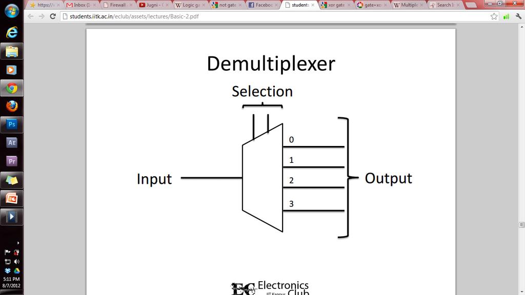
38 Demultiplexer
39 What s the difference? Since the connection is electrical, same IC can act as multiplexer as well as demultiplexer We call this Mux-Demux In particular, the above IC is 4052 a 4 * 1 MuxDemux * 1 Mux-Demux

40 Roulette

41 Designing a Toggle Switch Flip-Flop
42 Flip Flops : Truth Table In these configurations of S and D, the output of the Flip Flop does not depend on Clock or J, K and is S and D are kept low to for most of our applications. Looking at the truth Table, can you design a toggle switch??
43 Decimal to binary conversion Encoder (74148) Converts decimal to 3-bit binary High/low voltage on any of the 7 input pins gives corresponding binary representation of the number on output pins.
44 So far Electronics Digital and Analog Digital Electronics and Binary Number system Inter-conversion between Decimal and Binary Number system. Clock pulse and 555 timer IC 4029 counter IC 7447 and BCD Logic Gates AND, OR, NOT, NAND, NOR and XOR Multiplexer/Demultiplexer Flip-Flop Encoder
45 Electromania
46 Problem Statement The aim of the competition is to design the game Simon Says using LED s to represent the sequence. In this game, a sequence of LED glows randomly and the player has to memorize the sequence. The LED is turned off and now the player has to enter the sequence, which was shown. The game continues in case of a correct sequence guessed and ends otherwise.
47 Problem Statement
48 COMPULSARY FEATURES LED array: Minimum of five LEDs to display the sequence. Sequence Input: Five switches corresponding to each LED. Minimum sequence length: Your circuit must work for sequence length of at least one LED i.e. you should display any one LED randomly out of the 5 LEDs and then player needs to press the corresponding switch to win the game.
49 ADDITIONAL FEATURES Sequence length to be memorized can be increased up to 5. Scoring mechanism to count the number of correct sequence entered. These are just some of the additional features. Apart from these, any other innovative additional features can be implemented.
50 Eligibility & Team structure Students belonging to Y13 batch of any program (B.Tech, M.Tech etc.) are eligible. Team strength should be minimum 3 and maximum 4. No restrictions on number of teams from a pool. Though all members of a single team should belong to the same pool.
51 For other rules and further details visit : a.pdf
52 Why participate in Electromania??

53 Circuit design process Deciding the logic and preparing a block diagram

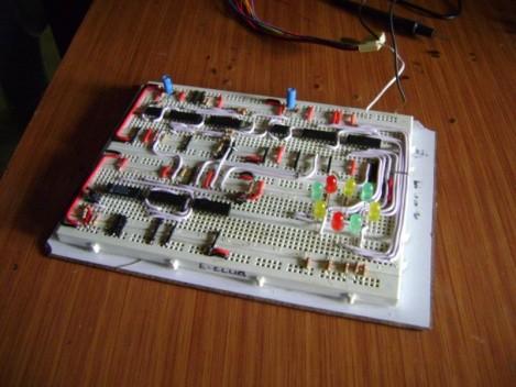
54 Circuit design process Making hardware connections and actual implementation.

55 Circuit design process Learn from mistakes..
56 Circuit design process All it requires is A bit of patience..!!

57 Circuit design process Challenge of Debugging

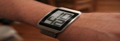
58 Circuit design process and then the The final Delight
59 A few things yet to cover.
60 4029 revisited Parallel load - Loads the value of Parallel Input bit into the output bits. TC bar Generates a clock pulse at every Counter overflow Up/Down mode Can be used to increment decrement at every clock pulse
61 Using a switch Never leave a input pin unconnected. Pull Up/Pull Down. () ()
62 DOs DON Ts Make tight connections. *Don t leave input pins unconnected Use proper wire convention. *Never control power pin of IC Use gates to combine outputs. *Never connect outputs directly Test the circuit regularly before making major changes. Keep in contact with Hall students.iitk.ac.in/eclub/contact.php) Secys(

63

64 Thanks Website : FB Group : eclub.iitk@gmail.com Youtube :
PHYSICS 5620 LAB 9 Basic Digital Circuits and Flip-Flops
 PHYSICS 5620 LAB 9 Basic Digital Circuits and Flip-Flops Objective Construct a two-bit binary decoder. Study multiplexers (MUX) and demultiplexers (DEMUX). Construct an RS flip-flop from discrete gates.
Bachelor Level/ First Year/ Second Semester/ Science Full Marks: 60 Computer Science and Information Technology (CSc. 151) Pass Marks: 24
 Pass Marks: 24") 2065 Computer Science and Information Technology (CSc. 151) Pass Marks: 24 Time: 3 hours. Candidates are required to give their answers in their own words as for as practicable. Attempt any TWO questions:
2065 Computer Science and Information Technology (CSc. 151) Pass Marks: 24 Time: 3 hours. Candidates are required to give their answers in their own words as for as practicable. Attempt any TWO questions:
Advanced Devices. Registers Counters Multiplexers Decoders Adders. CSC258 Lecture Slides Steve Engels, 2006 Slide 1 of 20
 Advanced Devices Using a combination of gates and flip-flops, we can construct more sophisticated logical devices. These devices, while more complex, are still considered fundamental to basic logic design.
Solution to Digital Logic )What is the magnitude comparator? Design a logic circuit for 4 bit magnitude comparator and explain it,
What is the magnitude comparator? Design a logic circuit for 4 bit magnitude comparator and explain it,") Solution to Digital Logic -2067 Solution to digital logic 2067 1.)What is the magnitude comparator? Design a logic circuit for 4 bit magnitude comparator and explain it, A Magnitude comparator is a combinational
Solution to Digital Logic -2067 Solution to digital logic 2067 1.)What is the magnitude comparator? Design a logic circuit for 4 bit magnitude comparator and explain it, A Magnitude comparator is a combinational
Dev Bhoomi Institute Of Technology Department of Electronics and Communication Engineering PRACTICAL INSTRUCTION SHEET
 Dev Bhoomi Institute Of Technology Department of Electronics and Communication Engineering PRACTICAL INSTRUCTION SHEET LABORATORY MANUAL EXPERIMENT NO. 1 ISSUE NO. : ISSUE DATE: REV. NO. : REV. DATE :
Experiment # 9. Clock generator circuits & Counters. Digital Design LAB
 Digital Design LAB Islamic University Gaza Engineering Faculty Department of Computer Engineering Fall 2012 ECOM 2112: Digital Design LAB Eng: Ahmed M. Ayash Experiment # 9 Clock generator circuits & Counters
Sequential Digital Design. Laboratory Manual. Experiment #7. Counters
 The Islamic University of Gaza Engineering Faculty Department of Computer Engineering Spring 2018 ECOM 2022 Khaleel I. Shaheen Sequential Digital Design Laboratory Manual Experiment #7 Counters Objectives
MODULAR DIGITAL ELECTRONICS TRAINING SYSTEM
 MODULAR DIGITAL ELECTRONICS TRAINING SYSTEM MDETS UCTECH's Modular Digital Electronics Training System is a modular course covering the fundamentals, concepts, theory and applications of digital electronics.
MODULE 3. Combinational & Sequential logic
 MODULE 3 Combinational & Sequential logic Combinational Logic Introduction Logic circuit may be classified into two categories. Combinational logic circuits 2. Sequential logic circuits A combinational
Figure 30.1a Timing diagram of the divide by 60 minutes/seconds counter
 Digital Clock The timing diagram figure 30.1a shows the time interval t 6 to t 11 and t 19 to t 21. At time interval t 9 the units counter counts to 1001 (9) which is the terminal count of the 74x160 decade
Contents Circuits... 1
 Contents Circuits... 1 Categories of Circuits... 1 Description of the operations of circuits... 2 Classification of Combinational Logic... 2 1. Adder... 3 2. Decoder:... 3 Memory Address Decoder... 5 Encoder...
IT T35 Digital system desigm y - ii /s - iii
 UNIT - III Sequential Logic I Sequential circuits: latches flip flops analysis of clocked sequential circuits state reduction and assignments Registers and Counters: Registers shift registers ripple counters
Chapter 2. Digital Circuits
 Chapter 2. Digital Circuits Logic gates Flip-flops FF registers IC registers Data bus Encoders/Decoders Multiplexers Troubleshooting digital circuits Most contents of this chapter were covered in 88-217
BCN1043. By Dr. Mritha Ramalingam. Faculty of Computer Systems & Software Engineering
 BCN1043 By Dr. Mritha Ramalingam Faculty of Computer Systems & Software Engineering mritha@ump.edu.my http://ocw.ump.edu.my/ authors Dr. Mohd Nizam Mohmad Kahar (mnizam@ump.edu.my) Jamaludin Sallim (jamal@ump.edu.my)
Counters
 Counters A counter is the most versatile and useful subsystems in the digital system. A counter driven by a clock can be used to count the number of clock cycles. Since clock pulses occur at known intervals,
Analogue Versus Digital [5 M]
![Analogue Versus Digital [5 M]](/thumbs/93/111640168.jpg "Analogue Versus Digital [5 M]") Q.1 a. Analogue Versus Digital [5 M] There are two basic ways of representing the numerical values of the various physical quantities with which we constantly deal in our day-to-day lives. One of the ways,
Q.1 a. Analogue Versus Digital [5 M] There are two basic ways of representing the numerical values of the various physical quantities with which we constantly deal in our day-to-day lives. One of the ways,
0 0/1 0/1 0/1 0/1 0/1 0/1 0/1 0/1 1 1 Stop bits. 11-bit Serial Data format
 Applications of Shift Registers The major application of a shift register is to convert between parallel and serial data. Shift registers are also used as keyboard encoders. The two applications of the
MODU LE DAY. Class-A, B, AB and C amplifiers - basic concepts, power, efficiency Basic concepts of Feedback and Oscillation. Day 1
 DAY MODU LE TOPIC QUESTIONS Day 1 Day 2 Day 3 Day 4 I Class-A, B, AB and C amplifiers - basic concepts, power, efficiency Basic concepts of Feedback and Oscillation Phase Shift Wein Bridge oscillators.
Operating Manual Ver.1.1
 Event Counter Operating Manual Ver.1.1 An ISO 9001 : 2000 company 94-101, Electronic Complex Pardesipura, Indore- 452010, India Tel : 91-731- 2570301/02, 4211100 Fax: 91-731- 2555643 e mail : info@scientech.bz
[2 credit course- 3 hours per week]
![[2 credit course- 3 hours per week]](/thumbs/94/121292011.jpg "[2 credit course- 3 hours per week]") Syllabus of Applied Electronics for F Y B Sc Semester- 1 (With effect from June 2012) PAPER I: Components and Devices [2 credit course- 3 hours per week] Unit- I : CIRCUIT THEORY [10 Hrs] Introduction;
Syllabus of Applied Electronics for F Y B Sc Semester- 1 (With effect from June 2012) PAPER I: Components and Devices [2 credit course- 3 hours per week] Unit- I : CIRCUIT THEORY [10 Hrs] Introduction;
Computer Systems Architecture
 Computer Systems Architecture Fundamentals Of Digital Logic 1 Our Goal Understand Fundamentals and basics Concepts How computers work at the lowest level Avoid whenever possible Complexity Implementation
MUHAMMAD NAEEM LATIF MCS 3 RD SEMESTER KHANEWAL
 1. A stage in a shift register consists of (a) a latch (b) a flip-flop (c) a byte of storage (d) from bits of storage 2. To serially shift a byte of data into a shift register, there must be (a) one click
SEQUENTIAL LOGIC. Satish Chandra Assistant Professor Department of Physics P P N College, Kanpur
 SEQUENTIAL LOGIC Satish Chandra Assistant Professor Department of Physics P P N College, Kanpur www.satish0402.weebly.com OSCILLATORS Oscillators is an amplifier which derives its input from output. Oscillators
EKT 121/4 ELEKTRONIK DIGIT 1
 EKT 121/4 ELEKTRONIK DIGIT 1 Kolej Universiti Kejuruteraan Utara Malaysia Bistable Storage Devices and Related Devices Introduction Latches and flip-flops are the basic single-bit memory elements used
TRAINING KITS ON DIGITAL ELECTRONIC EXPERIMENTS. Verify Truth table for TTL IC s AND, NOT, & NAND GATES
 TRAINING KITS ON DIGITAL ELECTRONIC EXPERIMENTS CEE 2800 Basic Logic Gates using TTL IC's (7 in 1) To verify the truth table For TTL AND, OR. NOT, NAND,NOR, EX-OR, & EX-NOR Gates. Instrument comprises
Find the equivalent decimal value for the given value Other number system to decimal ( Sample)
") VELAMMAL COLLEGE OF ENGINEERING AND TECHNOLOGY, MADURAI 65 009 Department of Information Technology Model Exam-II-Question bank PART A (Answer for all Questions) (8 X = 6) K CO Marks Find the equivalent
VELAMMAL COLLEGE OF ENGINEERING AND TECHNOLOGY, MADURAI 65 009 Department of Information Technology Model Exam-II-Question bank PART A (Answer for all Questions) (8 X = 6) K CO Marks Find the equivalent
DIGITAL CIRCUIT COMBINATORIAL LOGIC
 DIGITAL CIRCUIT COMBINATORIAL LOGIC Logic levels: one zero true false high low CMOS logic levels: 1 => 0.7 V DD 0.4 V DD = noise margin 0 =< 0.3 V DD Positive logic: high = 1 = true low = 0 = false Negative
ME 515 Mechatronics. Introduction to Digital Electronics
 ME 55 Mechatronics /5/26 ME 55 Mechatronics Digital Electronics Asanga Ratnaweera Department of Faculty of Engineering University of Peradeniya Tel: 8239 (3627) Email: asangar@pdn.ac.lk Introduction to
Logic Design Viva Question Bank Compiled By Channveer Patil
 Logic Design Viva Question Bank Compiled By Channveer Patil Title of the Practical: Verify the truth table of logic gates AND, OR, NOT, NAND and NOR gates/ Design Basic Gates Using NAND/NOR gates. Q.1
Slide 1. Flip-Flops. Cross-NOR SR flip-flop S R Q Q. hold reset set not used. Cross-NAND SR flip-flop S R Q Q. not used reset set hold 1 Q.
 Slide Flip-Flops Cross-NOR SR flip-flop Reset Set Cross-NAND SR flip-flop Reset Set S R reset set not used S R not used reset set 6.7 Digital ogic Slide 2 Clocked evel-triggered NAND SR Flip-Flop S R SR
Tribhuvan University Institute of Science and Technology Bachelor of Science in Computer Science and Information Technology
 Tribhuvan University Institute of Science and Technology Bachelor of Science in Computer Science and Information Technology Course Title: Digital Logic Full Marks: 60 + 0 + 0 Course No.: CSC Pass Marks:
Reaction Game Kit MitchElectronics 2019
 Reaction Game Kit MitchElectronics 2019 www.mitchelectronics.co.uk CONTENTS Schematic 3 How It Works 4 Materials 6 Construction 8 Important Information 9 Page 2 SCHEMATIC Page 3 SCHEMATIC EXPLANATION The
EEE130 Digital Electronics I Lecture #1_2. Dr. Shahrel A. Suandi
 EEE130 Digital Electronics I Lecture #1_2 Dr. Shahrel A. Suandi 1-4 Overview of Basic Logic Functions Digital systems are generally built from combinations of NOT, AND and OR logic elements The combinations
EE292: Fundamentals of ECE
 EE292: Fundamentals of ECE Fall 2012 TTh 10:00-11:15 SEB 1242 Lecture 23 121120 http://www.ee.unlv.edu/~b1morris/ee292/ 2 Outline Review Combinatorial Logic Sequential Logic 3 Combinatorial Logic Circuits
Digital Fundamentals: A Systems Approach
 Digital Fundamentals: A Systems Approach Latches, Flip-Flops, and Timers Chapter 6 Traffic Signal Control Traffic Signal Control: State Diagram Traffic Signal Control: Block Diagram Traffic Signal Control:
Chapter 5 Flip-Flops and Related Devices
 Chapter 5 Flip-Flops and Related Devices Chapter 5 Objectives Selected areas covered in this chapter: Constructing/analyzing operation of latch flip-flops made from NAND or NOR gates. Differences of synchronous/asynchronous
2. Counter Stages or Bits output bits least significant bit (LSB) most significant bit (MSB) 3. Frequency Division 4. Asynchronous Counters
 most significant bit (MSB) 3. Frequency Division 4. Asynchronous Counters") 2. Counter Stages or Bits The number of output bits of a counter is equal to the flip-flop stages of the counter. A MOD-2 n counter requires n stages or flip-flops in order to produce a count sequence
2. Counter Stages or Bits The number of output bits of a counter is equal to the flip-flop stages of the counter. A MOD-2 n counter requires n stages or flip-flops in order to produce a count sequence
Experiment 8 Introduction to Latches and Flip-Flops and registers
 Experiment 8 Introduction to Latches and Flip-Flops and registers Introduction: The logic circuits that have been used until now were combinational logic circuits since the output of the device depends
Logic Design. Flip Flops, Registers and Counters
 Logic Design Flip Flops, Registers and Counters Introduction Combinational circuits: value of each output depends only on the values of inputs Sequential Circuits: values of outputs depend on inputs and
NORTHWESTERN UNIVERSITY TECHNOLOGICAL INSTITUTE
 NORTHWESTERN UNIVERSITY TECHNOLOGICL INSTITUTE ECE 270 Experiment #8 DIGITL CIRCUITS Prelab 1. Draw the truth table for the S-R Flip-Flop as shown in the textbook. Draw the truth table for Figure 7. 2.
Asynchronous (Ripple) Counters
 Counters") Circuits for counting events are frequently used in computers and other digital systems. Since a counter circuit must remember its past states, it has to possess memory. The chapter about flip-flops introduced
Circuits for counting events are frequently used in computers and other digital systems. Since a counter circuit must remember its past states, it has to possess memory. The chapter about flip-flops introduced
DEPARTMENT OF COMPUTER SCIENCE & ENGINEERING
 DRONACHARYA GROUP OF INSTITUTIONS, GREATER NOIDA Affiliated to Mahamaya Technical University, Noida Approved by AICTE DEPARTMENT OF COMPUTER SCIENCE & ENGINEERING Lab Manual for Computer Organization Lab
Chapter Contents. Appendix A: Digital Logic. Some Definitions
 A- Appendix A - Digital Logic A-2 Appendix A - Digital Logic Chapter Contents Principles of Computer Architecture Miles Murdocca and Vincent Heuring Appendix A: Digital Logic A. Introduction A.2 Combinational
4.S-[F] SU-02 June All Syllabus Science Faculty B.Sc. II Yr. Instrumentation Practice [Sem.III & IV] S.Lot
![4.S-[F] SU-02 June All Syllabus Science Faculty B.Sc. II Yr. Instrumentation Practice [Sem.III & IV] S.Lot](/thumbs/90/103282534.jpg "4.S-[F] SU-02 June All Syllabus Science Faculty B.Sc. II Yr. Instrumentation Practice [Sem.III & IV] S.Lot") [Sem.III & IV] S.Lot. - 1 - [Sem.III & IV] S.Lot. - 2 - [Sem.III & IV] S.Lot. - 3 - Syllabus B.Sc. ( Instrumentation Practice ) Second Year ( Third and Forth Semester ) ( Effective from June 2014 ) [Sem.III
[Sem.III & IV] S.Lot. - 1 - [Sem.III & IV] S.Lot. - 2 - [Sem.III & IV] S.Lot. - 3 - Syllabus B.Sc. ( Instrumentation Practice ) Second Year ( Third and Forth Semester ) ( Effective from June 2014 ) [Sem.III
Principles of Computer Architecture. Appendix A: Digital Logic
 A-1 Appendix A - Digital Logic Principles of Computer Architecture Miles Murdocca and Vincent Heuring Appendix A: Digital Logic A-2 Appendix A - Digital Logic Chapter Contents A.1 Introduction A.2 Combinational
Introduction to Digital Logic Missouri S&T University CPE 2210 Exam 3 Logistics
 Introduction to Digital Logic Missouri S&T University CPE 2210 Exam 3 Logistics Egemen K. Çetinkaya Egemen K. Çetinkaya Department of Electrical & Computer Engineering Missouri University of Science and
Introduction. NAND Gate Latch. Digital Logic Design 1 FLIP-FLOP. Digital Logic Design 1
 2007 Introduction BK TP.HCM FLIP-FLOP So far we have seen Combinational Logic The output(s) depends only on the current values of the input variables Here we will look at Sequential Logic circuits The
WINTER 15 EXAMINATION Model Answer
 Important Instructions to examiners: 1) The answers should be examined by key words and not as word-to-word as given in the model answer scheme. 2) The model answer and the answer written by candidate
TYPICAL QUESTIONS & ANSWERS
 DIGITALS ELECTRONICS TYPICAL QUESTIONS & ANSWERS OBJECTIVE TYPE QUESTIONS Each Question carries 2 marks. Choose correct or the best alternative in the following: Q.1 The NAND gate output will be low if
Registers and Counters
 Registers and Counters Clocked sequential circuit = F/Fs and combinational gates Register Group of flip-flops (share a common clock and capable of storing one bit of information) Consist of a group of
Computer Architecture and Organization
 A-1 Appendix A - Digital Logic Computer Architecture and Organization Miles Murdocca and Vincent Heuring Appendix A Digital Logic A-2 Appendix A - Digital Logic Chapter Contents A.1 Introduction A.2 Combinational
Registers and Counters
 Registers and Counters Clocked sequential circuit = F/Fs and combinational gates Register Group of flip-flops (share a common clock and capable of storing one bit of information) Consist of a group of
Decade Counters Mod-5 counter: Decade Counter:
 Decade Counters We can design a decade counter using cascade of mod-5 and mod-2 counters. Mod-2 counter is just a single flip-flop with the two stable states as 0 and 1. Mod-5 counter: A typical mod-5
CHAPTER 1 LATCHES & FLIP-FLOPS
 CHAPTER 1 LATCHES & FLIP-FLOPS 1 Outcome After learning this chapter, student should be able to; Recognize the difference between latches and flipflops Analyze the operation of the flip flop Draw the output
Logic and Computer Design Fundamentals. Chapter 7. Registers and Counters
 Logic and Computer Design Fundamentals Chapter 7 Registers and Counters Registers Register a collection of binary storage elements In theory, a register is sequential logic which can be defined by a state
Counter dan Register
 Counter dan Register Introduction Circuits for counting events are frequently used in computers and other digital systems. Since a counter circuit must remember its past states, it has to possess memory.
Rangkaian Sekuensial. Flip-flop
 Rangkaian Sekuensial Rangkaian Sekuensial Flip-flop Combinational versus Sequential Functions Logic functions are categorized as being either combinational (sometimes referred to as combinatorial) or sequential.
Chapter 7 Counters and Registers
 Chapter 7 Counters and Registers Chapter 7 Objectives Selected areas covered in this chapter: Operation & characteristics of synchronous and asynchronous counters. Analyzing and evaluating various types
Logic Gates, Timers, Flip-Flops & Counters. Subhasish Chandra Assistant Professor Department of Physics Institute of Forensic Science, Nagpur
 Logic Gates, Timers, Flip-Flops & Counters Subhasish Chandra Assistant Professor Department of Physics Institute of Forensic Science, Nagpur Logic Gates Transistor NOT Gate Let I C be the collector current.
Chapter 4. Logic Design
 Chapter 4 Logic Design 4.1 Introduction. In previous Chapter we studied gates and combinational circuits, which made by gates (AND, OR, NOT etc.). That can be represented by circuit diagram, truth table
Flip-Flops and Sequential Circuit Design
 Flip-Flops and Sequential Circuit Design ECE 52 Summer 29 Reading ssignment Brown and Vranesic 7 Flip-Flops, Registers, Counters and a Simple Processor 7.5 T Flip-Flop 7.5. Configurable Flip-Flops 7.6
FUNCTIONS OF COMBINATIONAL LOGIC
 FUNCTIONS OF COMBINATIONAL LOGIC Agenda Adders Comparators Decoders Encoders Multiplexers Demultiplexers Adders Basic Adders Adders are important in computers other types of digital systems in which numerical
Department of Electrical and Computer Engineering Mid-Term Examination Winter 2012
 1 McGill University Faculty of Engineering ECSE-221B Introduction to Computer Engineering Department of Electrical and Computer Engineering Mid-Term Examination Winter 2012 Examiner: Rola Harmouche Date:
QUICK GUIDE COMPUTER LOGICAL ORGANIZATION - OVERVIEW
 QUICK GUIDE http://www.tutorialspoint.com/computer_logical_organization/computer_logical_organization_quick_guide.htm COMPUTER LOGICAL ORGANIZATION - OVERVIEW Copyright tutorialspoint.com In the modern
UNIVERSITI TEKNOLOGI MALAYSIA
 SULIT Faculty of Computing UNIVERSITI TEKNOLOGI MALAYSIA FINAL EXAMINATION SEMESTER I, 2016 / 2017 SUBJECT CODE : SUBJECT NAME : SECTION : TIME : DATE/DAY : VENUES : INSTRUCTIONS : Answer all questions
Serial In/Serial Left/Serial Out Operation
 Shift Registers The need to storage binary data was discussed earlier. In digital circuits multi-bit data has to be stored temporarily until it is processed. A flip-flop is able to store a single binary
CHW 261: Logic Design
 CHW 26: Logic Design Instructors: Prof. Hala Zayed Dr. Ahmed Shalaby http://www.bu.edu.eg/staff/halazayed4 http://bu.edu.eg/staff/ahmedshalaby4# Slide Digital Fundamentals CHAPTER 7 Latches, Flip-Flops
Computer Organization & Architecture Lecture #5
 Computer Organization & Architecture Lecture #5 Shift Register A shift register is a register in which binary data can be stored and then shifted left or right when a shift signal is applied. Bits shifted
R13 SET - 1 '' ''' '' ' '''' Code No: RT21053
 SET - 1 1. a) What are the characteristics of 2 s complement numbers? b) State the purpose of reducing the switching functions to minimal form. c) Define half adder. d) What are the basic operations in
LATCHES & FLIP-FLOP. Chapter 7
 LATCHES & FLIP-FLOP Chapter 7 INTRODUCTION Latch and flip flops are categorized as bistable devices which have two stable states,called SET and RESET. They can retain either of this states indefinitely
Today 3/8/11 Lecture 8 Sequential Logic, Clocks, and Displays
 Today 3/8/ Lecture 8 Sequential Logic, Clocks, and Displays Flip Flops and Ripple Counters One Shots and Timers LED Displays, Decoders, and Drivers Homework XXXX Reading H&H sections on sequential logic
Electrical and Telecommunications Engineering Technology_TCET3122/TC520. NEW YORK CITY COLLEGE OF TECHNOLOGY The City University of New York
 NEW YORK CITY COLLEGE OF TECHNOLOGY The City University of New York DEPARTMENT: SUBJECT CODE AND TITLE: COURSE DESCRIPTION: REQUIRED: Electrical and Telecommunications Engineering Technology TCET 3122/TC
1. Convert the decimal number to binary, octal, and hexadecimal.
 1. Convert the decimal number 435.64 to binary, octal, and hexadecimal. 2. Part A. Convert the circuit below into NAND gates. Insert or remove inverters as necessary. Part B. What is the propagation delay
ECB DIGITAL ELECTRONICS PROJECT BASED LEARNING PROJECT REPORT ON 7 SEGMENT DIGITAL STOP WATCH USING DECODER
 ECB2212 - DIGITAL ELECTRONICS PROJECT BASED LEARNING PROJECT REPORT ON 7 SEGMENT DIGITAL STOP WATCH USING DECODER SUBMITTED BY ASHRAF HUSSAIN (160051601105) S SAMIULLAH (160051601059) CONTENTS >AIM >INTRODUCTION
Flip Flop. S-R Flip Flop. Sequential Circuits. Block diagram. Prepared by:- Anwar Bari
 Sequential Circuits The combinational circuit does not use any memory. Hence the previous state of input does not have any effect on the present state of the circuit. But sequential circuit has memory
Long and Fast Up/Down Counters Pushpinder Kaur CHOUHAN 6 th Jan, 2003
 1 Introduction Long and Fast Up/Down Counters Pushpinder Kaur CHOUHAN 6 th Jan, 2003 Circuits for counting both forward and backward events are frequently used in computers and other digital systems. Digital
CHAPTER 6 COUNTERS & REGISTERS
 CHAPTER 6 COUNTERS & REGISTERS 6.1 Asynchronous Counter 6.2 Synchronous Counter 6.3 State Machine 6.4 Basic Shift Register 6.5 Serial In/Serial Out Shift Register 6.6 Serial In/Parallel Out Shift Register
problem maximum score 1 28pts 2 10pts 3 10pts 4 15pts 5 14pts 6 12pts 7 11pts total 100pts
 University of California at Berkeley College of Engineering Department of Electrical Engineering and Computer Sciences EECS150 J. Wawrzynek Spring 2002 4/5/02 Midterm Exam II Name: Solutions ID number:
Digital Fundamentals: A Systems Approach
 Digital Fundamentals: A Systems Approach Counters Chapter 8 A System: Digital Clock Digital Clock: Counter Logic Diagram Digital Clock: Hours Counter & Decoders Finite State Machines Moore machine: One
Midterm Exam 15 points total. March 28, 2011
 Midterm Exam 15 points total March 28, 2011 Part I Analytical Problems 1. (1.5 points) A. Convert to decimal, compare, and arrange in ascending order the following numbers encoded using various binary
CHAPTER 4 RESULTS & DISCUSSION
 CHAPTER 4 RESULTS & DISCUSSION 3.2 Introduction This project aims to prove that Modified Baugh-Wooley Two s Complement Signed Multiplier is one of the high speed multipliers. The schematic of the multiplier
Digital Systems Laboratory 3 Counters & Registers Time 4 hours
 Digital Systems Laboratory 3 Counters & Registers Time 4 hours Aim: To investigate the counters and registers constructed from flip-flops. Introduction: In the previous module, you have learnt D, S-R,
YEDITEPE UNIVERSITY DEPARTMENT OF COMPUTER ENGINEERING. EXPERIMENT VIII: FLIP-FLOPS, COUNTERS 2014 Fall
 YEDITEPE UNIVERSITY DEPARTMENT OF COMPUTER ENGINEERING EXPERIMENT VIII: FLIP-FLOPS, COUNTERS 2014 Fall Objective: - Dealing with the operation of simple sequential devices. Learning invalid condition in
PHYS 3322 Modern Laboratory Methods I Digital Devices
 PHYS 3322 Modern Laboratory Methods I Digital Devices Purpose This experiment will introduce you to the basic operating principles of digital electronic devices. Background These circuits are called digital
1 Hour Sample Test Papers: Sample Test Paper 1. Roll No.
 6.1.2 Sample Test Papers: Sample Test Paper 1 Roll No. Institute Name: Course Code: EJ/EN/ET/EX/EV/IC/IE/IS/MU/DE/ED/ET/IU Subject: Principles of Digital Techniques Marks: 25 1 Hour 1. All questions are
R13. II B. Tech I Semester Regular Examinations, Jan DIGITAL LOGIC DESIGN (Com. to CSE, IT) PART-A
 PART-A") SET - 1 Note: Question Paper consists of two parts (Part-A and Part-B) Answer ALL the question in Part-A Answer any THREE Questions from Part-B a) What are the characteristics of 2 s complement numbers?
SET - 1 Note: Question Paper consists of two parts (Part-A and Part-B) Answer ALL the question in Part-A Answer any THREE Questions from Part-B a) What are the characteristics of 2 s complement numbers?
Final Exam review: chapter 4 and 5. Supplement 3 and 4
 Final Exam review: chapter 4 and 5. Supplement 3 and 4 1. A new type of synchronous flip-flop has the following characteristic table. Find the corresponding excitation table with don t cares used as much
Introduction. Serial In - Serial Out Shift Registers (SISO)
") Introduction Shift registers are a type of sequential logic circuit, mainly for storage of digital data. They are a group of flip-flops connected in a chain so that the output from one flip-flop becomes
Introduction Shift registers are a type of sequential logic circuit, mainly for storage of digital data. They are a group of flip-flops connected in a chain so that the output from one flip-flop becomes
Logic. Andrew Mark Allen March 4, 2012
 Logic Andrew Mark Allen - 05370299 March 4, 2012 Abstract NAND gates and inverters were used to construct several different logic gates whose operations were investigate under various inputs. Then the
VU Mobile Powered by S NO Group
 Question No: 1 ( Marks: 1 ) - Please choose one A 8-bit serial in / parallel out shift register contains the value 8, clock signal(s) will be required to shift the value completely out of the register.
DepartmentofElectronicEngineering NEDUniversity ofengineering &Technology LABORATORY WORKBOOK DIGITAL LOGIC DESIGN (TC-201)
") DepartmentofElectronicEngineering NEDUniversity ofengineering &Technology LABORATORY WORKBOOK DIGITAL LOGIC DESIGN (TC-201) Instructor Name: Student Name: Roll Number: Semester: Batch: Year: Department:
DepartmentofElectronicEngineering NEDUniversity ofengineering &Technology LABORATORY WORKBOOK DIGITAL LOGIC DESIGN (TC-201) Instructor Name: Student Name: Roll Number: Semester: Batch: Year: Department:
CHAPTER 4: Logic Circuits
 CHAPTER 4: Logic Circuits II. Sequential Circuits Combinational circuits o The outputs depend only on the current input values o It uses only logic gates, decoders, multiplexers, ALUs Sequential circuits
SAULT COLLEGE OF APPLIED ARTS & TECHNOLOGY SAULT STE. MARIE, ONTARIO LOGIC & SWITCHING CIRCUITS NON-SEMESTERED TECHNICIAN PROGRAM
 SAULT COLLEGE OF APPLED ARTS & TECHNOLOGY SAULT STE. MARE, ONTARO COURSE OUTLNE Course Title: LOGC & SWTCHNG CRCUTS Code No.: ELN 207 Program: Semester: Date: Author: NON-SEMESTERED TECHNCAN PROGRAM THREE
Lecture 12. Amirali Baniasadi
 CENG 24 Digital Design Lecture 2 Amirali Baniasadi amirali@ece.uvic.ca This Lecture Chapter 6: Registers and Counters 2 Registers Sequential circuits are classified based in their function, e.g., registers.
Flip-Flops and Related Devices. Wen-Hung Liao, Ph.D. 4/11/2001
 Flip-Flops and Related Devices Wen-Hung Liao, Ph.D. 4/11/2001 Objectives Recognize the various IEEE/ANSI flip-flop symbols. Use state transition diagrams to describe counter operation. Use flip-flops in
Review : 2 Release Date : 2019 Last Amendment : 2013 Course Code : SKEE 2742 Procedure Number : PK-UTM-FKE-(0)-10
-10") School Course Name : : ELECTRICAL ENGINEERING 2 ND YEAR ELECTRONIC DESIGN LAB Review : 2 Release Date : 2019 Last Amendment : 2013 Course Code : SKEE 2742 Procedure Number : PK-UTM-FKE-(0)-10 School of
School Course Name : : ELECTRICAL ENGINEERING 2 ND YEAR ELECTRONIC DESIGN LAB Review : 2 Release Date : 2019 Last Amendment : 2013 Course Code : SKEE 2742 Procedure Number : PK-UTM-FKE-(0)-10 School of
Chapter 9 MSI Logic Circuits
 Chapter 9 MSI Logic Circuits Chapter 9 Objectives Selected areas covered in this chapter: Analyzing/using decoders & encoders in circuits. Advantages and disadvantages of LEDs and LCDs. Observation/analysis
MAHARASHTRA STATE BOARD OF TECHNICAL EDUCATION (Autonomous) (ISO/IEC Certified)
 (ISO/IEC Certified)") Important Instructions to examiners: 1) The answers should be examined by key words and not as word-to-word as given in the model answer scheme. 2) The model answer and the answer written by candidate
Important Instructions to examiners: 1) The answers should be examined by key words and not as word-to-word as given in the model answer scheme. 2) The model answer and the answer written by candidate
DIGITAL ELECTRONICS LAB MANUAL FOR 2/4 B.Tech (ECE) COURSE CODE: EC-252
 COURSE CODE: EC-252") DIGITAL ELECTRONICS LAB MANUAL FOR /4 B.Tech (ECE) COURSE CODE: EC-5 PREPARED BY P.SURENDRA KUMAR M.TECH, Lecturer D.SWETHA M.TECH, Lecturer T Srinivasa Rao M.TECH, Lecturer Ch.Madhavi, Lab Assistant 009-00
DIGITAL ELECTRONICS LAB MANUAL FOR /4 B.Tech (ECE) COURSE CODE: EC-5 PREPARED BY P.SURENDRA KUMAR M.TECH, Lecturer D.SWETHA M.TECH, Lecturer T Srinivasa Rao M.TECH, Lecturer Ch.Madhavi, Lab Assistant 009-00
EKT 121/4 ELEKTRONIK DIGIT 1
 EKT 2/4 ELEKTRONIK DIGIT Kolej Universiti Kejuruteraan Utara Malaysia Sequential Logic Circuits - COUNTERS - LATCHES (review) S-R R Latch S-R R Latch Active-LOW input INPUTS OUTPUTS S R Q Q COMMENTS Q