The largest selection
|
|
|
- Lucy Dalton
- 5 years ago
- Views:
Transcription

1


2 The largest selection BRAND NEW FULLY GUARANTEED DEVICES AC107 ISp AF I 15 lip BC140 35p BCY31 22p 6E p AC I 13 20p AF116 17p BC' 41 35p BCY32 25p BF273 30p AC p AF p BC p BCY33 17p BF274 30p AC125 17p AFI 18 30p BC I 43 40p BCY34 lop BF308 33p AC126 17p AF I 24 lip 8C145 45p BCY70 17p BF309 37p AC p AFI 2S 10p BCI47 17p BCY71 30p BF316 7Sp ACI28 17p AF126 20p 8C148 12p BCY72 15p BFW I 0 55p AC I 4IK 17p AF p BCI49 17p BCZ II 20p BF X29 2.7p AC I 42K 17p AF I 39 lip BC150 17p BDI21 115p BFX84 2.0p AC p AF178 50p BC151 20p p BF X85 17p ACIS4 ISp AF179 50p BCI52 17p p BF X86 lip AC p AF p BCI53 27p p BFX87 25p ACI 56 17p AFI91 50p BCI54 30p p BFX88 lip ACI57 17p AF186 45p BC I57 20p BDY20 LI BFY50 111p AC165 17p AF239 37p BCI58 17p BF I 15 21p BFY51 20p AC166 17p AF Z I I lip BC I 59 20p BF p BFY52 lop ACI67 20p AFZ12 4Sp BCI67 13p BF118 60p BFY53 17p AC168 20p AL p BC 168 lip BF119 70p 135)(19 13p AC169 14p A p BC169 13p 8E152 35p 85)(20 15p AC176 13p ASY26 23p BC I70 lip BF I 53 33p p AC177 20p A p BC171 lip BFI54 35p BSY26 15p AC187 30p ASY28 25p BC 1 72 Ilp BFI57 45p 85'127 15p ACI88 ]Op A p BCI73 13p BFI58 13p B5Y28 15p ACYI7 25p ASYSO 13p BC174 13p BFI59 30p 15p ACY18 20p ASYSI lip BC p BFI60 30p ISp ACYI9 12p ASY52 25p BC177 17p BF162 30p p ACY20 20p ASY54 25p BC 178 lip BF I 63 35p p ACY2 I Illp A p BC I 79 17p BFI64 35p p ACY22 ISp ASY56 23p BC p BFI65 33p B5Y95 12p ACY27 18p A p BC181 lip BF 67 lip BSY95A 12p ACY28 19p A p BC p BFI73 lip BU I 05 L3.90 ACY29 30p p BC I 82L 10p BF176 35p CI I 1E 60p ACY30 25p AS Z2 I 40p BC p BF177 35p C400 30p ACY3 I 2.5p BC107 10p BC 183L 10p BF p C407 25p ACY34 18p BC108 10p BC I 84 Ilp BF I 79 50p C424 17p ACY35 ISp BC109 lip BC I 84L lip BFI80 30p C425 40p ACY36 30p BC I 13 25p BC p BF181 30p C426 30p ACY40 15p BCII4 30p BC187 27p BFI C428 11:1p ACY4 1 18p BC I 15 30p BC207 I 1 p BFI83 30p C441 17p ACY44 35p BC116 35p BC209 lip BF p C442 35p A p BC p BC209 1 I p 8E185 30p p A p BC p BC212L 1 1 p BF I 88 30p C450 17p ADI 49 43p BC p 5C2131 I I p BF I 94 23p C720 lip ADI 61 35p BCI25 35p BC2 I 3L lip BF I 95 14p C722 15p AD I 62 35p BC126 isp BC2I 4L lip 8F I 96 30p C740 15p AD161/ BC p BC225 25p BF I 97 33p C742 17p 162(11P) 63p 8C134 30p BC226 35p BF200 45p C744 17p ADT140 50p 8C135 30p BC3 I 7 lip BF p p ADZ II 12 BC p BC3I8 lip BF257 35p C762 17p ADZ I2 L2 10 BC137 35p BC3 I 9 12p BF270 25p C764 60p AFI 14 I7p BCI 39 45p BC230 20p BF27I 17p EC401 15p EC403 GET880 MAT100 MATIOI MAT 120 MATI21 MPF 102 MPF105 OC 19 0C20 0C22 0C23 0C24 0C25 0C26 0C28 0C C36 0C41 0C42 0C44 OCIS C139 0C140 0C170 0C171 0C200 0C201 0C202 0C203 0C204 0C205 0C309 P346A 9397 OCP71 ORP I2 1Sp 27p 15p 17p 13p 17p 43p 43p 30p 30p 30p 33p 45p 25p 23p p 33p 40p 111ip 22p 15p 12p 15p 9p lip 12p 15p 15p isp 15p 15p 15p 15p 10p 20p 15p 17p 15p 15p 25p 17p 27p 25p lip 35p 35p 17p p ORP60 ORP6 I UT46 V405A V4 I OA 2G A 2G G G382 2G G417 2N388 2N388A 2N404 2N404A 2N524 2N527 2N696 2N697 2N698 2N699 2N706 2N706A 2N708 1 N709 2N7 I I 2Nu I 7 2N718 2N7 I 8A 2N726 2N727 2N743 2N744 2N914 40p 40 Ilp 17p 40 p 27p 25p 45p 19p 19p 19p 20p 35p 35p 35p 17p 15p 13p 15p 13p 10p 17p lip 13p 15p 30p 30p 25p 30p 50p lip 30p 55p p 15p 24p 53p 7p Op 12p p 14p 50p 17p 2.7p lip 17p 17p 2N918 30p p p lip p p 2N2904A 30p Ilp 2N p p p 2N p 2N2905A 30p Sp 211 I p 2N p Bp 2N p 2N2906A 2.7p 2N p p p 2N p 2N p p I 9 40p 2N1306 lip 2N p 2N3820 LI 2N 1307 lip 2N2924 lip 2N p 2N1308 lip 2N2925 I 1p p 2/ p p p (G) 12p p 2N I71 I 20p ISp p (Y) Ilp 2N p 2N1890 4Sp N p 2N p (0) 10p 2N p 2N3010 Sop p p 2N3011 lop 2N5172 Ilp p 2N p p 3N p 2N p p 2N p 2N3055 Sip SOp 2N p 2N p 25302A 43p p 2N3391A 20p p 2N N p p I 9 27p p LI.10 2N2220 lip 2N3394 ISp LI p p LI p p L1' p lip ISp 2N p p p 2N p 25322A 43p 2/92111 SOp 2/ p p 2N p I 5 20p II, I 6 35p 2N34 I 7 lip LI -20 2/ p p p 2N3702 lip '20 2N p 2N3703 lip DIODES & RECTIFIERS AA119 AAI20 BAI 16 BA126 BY I00 BY I Bp p BYZIO 22p BY Z I 2.1p 51Z12 15p BYZI 3 lip BYZI6 15p BYZI7 12p ISp BYZI 8 BYZ19 17p OAS 15p 35p lip 30p isp 35p 35p 30p 25p lip 0A10 0A47 0A70 0A79 OABI 0A135 0A90 0A91 0A95 0A200 21p 7p Bp 7p 7p 6p 7p 7p 6p r- 74 Series T.T.L. I.C-s DOWN AGAIN IN PRICE Check our 74 Series List before you buy any Our prices are the lowest possible. All devices es -duck. Full epro. guarapteed BI -PAX Price and qty. prices BI -PAR Price and qty. prices Order No up Order No up 22 Lp Lp Op Op fp = BPOI =SN BP02 -BN740' P54 = BP03 = BP60 - SN b = B070=9N BP115-9N BP BP HP08= B BP09= BP BP B076 = BP13 = SN / BP BPs1= BP17 = BP ' Bp92= 9574/ BP30-9N BM= =8574, BP90 = B1' BP91 = Et P42 = ED: BP99 =S BP B BP95 = BP ii; = ' BP100 = L:r BP.iii is X B ii BP SN ' ' B P BP B BP BP ' BP165 = SN = BP192= BP BP X ' BP PRICE -MIX. Devices may be mixed II) qualify for quantity prices. PRICES for quantities in excess of 500 pieces mixed, on application. Owing to the ever increasing range of TTL 74 Series. plea -se check with us for supplies of any devices not listed above, ns it is probably now in stock. WARE 3442 * STOP PRESS *! NOW OPEN BI-PAK'S NEW COMPONENT SHOP A wide range of all types of electronic components and equipment available at competitive prices. Expert technical advice freely given. 18 Baldock St. (MO), Ware, Herts. Tel.: OPEN Tues. to Sats. FRIDAYS UNTIL 8 ANOTHER BI-PAK FIRST! THE NEW S.G S. EA 1000 AUDIO AMPLIFIER MODULE * Guaranteed not /ess than 3 Watts RMS. Especially designed by S.G.S. incorporating their proven Linear I.C. Audio Amp. TA/621 providing unlimited applications for the enthusiast in the construction of radios, record players, Audio and Stereo units. Also ideal for intercom systems, monitoring applications and phone answering machines. OTHER USES: portable applications where supply rails as -low as 9V are of prime importance. Sensitivity 40 mv for I watt. VOLT- Typical Total Harmonic distortion at I watt AGE GAIN 40 db but can be varied less than 1%. up to 73 db for some applications. * Supply Voltage (Vs) = 24V 15 ohm load. Signal to Noise Ratio 86 db. Modual Tested and Guaranteed. Frequency response better than 50 Hz Qty. 1-9 L263; El.28 Price each to 25 KHz for -3 db. Larger quantities quoted on request. Full hook-up Normal supply Voltage 9-24V. diagrams and complete technical data supplied Li Suitable for 8-16 Ohm loads. free with each modual or available separately at Overall Site 2 in. x 3 in. x in. 10p each. All prices quoted in new pence Giro No Please send all orders direct fo warehouse and despatch department BINPAK P.O. BOX 6, WARE HERTS Postage and packing add 1p Overseas add eclra for airmail Minimum order 50p Cash with order please. Guaranteed Satisfaction or Money Back
. COSSOR CT1700U to CT2378A 5.00. DECCA DM4C (70 ), DR1, DR2, DR121 4.")

3 193 LINE OUTPUT TRANSFORMERS ALBA 1090, 1135, 1195, 1235, 1395, ARGOSY 17K10, 17K11, 17K12, 17K14, 19K17. 17K BAIRD All models price 590. From model 600 quote part no. normally found on TX base plate. BUSH TV53 to TUG TV91 to TV TV141 to TV186 please state part number TV75 to TV (except TV80). COSSOR CT1700U to CT2378A DECCA DM4C (70 ), DR1, DR2, DR DR95, DR DEFIANT 9A40 to 9A63. Prices on request. DYNATRON TV30, TV35, N36, TV37, TV38, TV39, TV40, TV41, etc EKCO T231, T284, TC267, T283, T293, T311, T326, T327, T330, TM B272, T344, 7344F, T345, TP347, T348, T348F, TC347, TC349, TC356, T368, 1370, TC369, T371, T372, TP373, TC374, T377A, T393, T394, 433, 434, 435, 436, 437 all at FERGUSON 306T, 308T, 406T, 408T, 416, 436, 438, 506, 508, 516, 518, 536, 546, 604, 606, 608, 616, 619, , 648, 725, 726, 727, 3600, 3601, 3602, 3604, 3611, 3612, 3614, 3617, 3618, 3619, 3620, , 3623, 3624, 3625, 3626, 3627, FERRANTI T1001, T1002, T1002/1, T1004, T1005, T1023, T1024, T1027, T1027F, TP1026, T1071, T1072, T1121, TC1122, TC1124, T1125, TC , G.E.C. BT302, BT BT454DST-456DST , 2014, 2015, 2000DS DS, 2002DS H.M.V. 1865, 1869, 1870, 1872, 1874, 1876, 1890, 1892, 1894, All models to KB OV30, N F70, NV40, PV40, QV10, QV3O, RV10, RV20, RV30, PVP Featherlight VC1 -VC2-VC3-VC MASTERADIO 4013 DST, D500 DST, D507 DST MARCONI VT153, VT155, VT156, VT157, VT159, VT161, VT163, VT165, VT170, 4611, 4800, 4801, 4803, MURPHY V310 to PAM 600S to PETO SCOTT. Prices on request. PHILCO 1019, 1020, , 1110, 5600, 5601, 5602, PHILIPS 11TG190 to 24T PILOT PT450, 452, 455, 650, PT651, P60A, P PYE V200, V400, 200LB, 210, 220, 300F, 3005, 310, 210S, 410, 510, 530, 600, 620, 630, 700 A or D, 710 A or D, 830 A or D or LBA U Series, 11 U-P/NO, AL21003, 21 F to 61. Part Nos must be given when ordering Pye LOPTS. REGENTONE , 298, TV402, TV401, TV501, TV , 10-21, 17-18, 10-12, R.G.D. 626, 627, 628, 726, RV202, RV C, SOBELL 1000DS, 1002DS, 1005DS, 1010DST, , 1014, 1018, 1019, , 1032, 1033, 1038, STELLA T1011U to 2149A ULTRA , 1772,1782, 2172, 1771, 2171, 1775, 2175, 1774, 2174, 1773, 2137, 1980c, 1984c, 100c, 200c, , 1984, 1985, 1986, 1980, 1980a, 1780, 2180, 2181, , 1871, 1783, 6600, , 6628, 6632, 6642 etc Post and Packing 26p. C.O.D. 30p extra. SAE ALL ENQUIRIES. Dept. "R" E. J. PAPWORTH AND SON LTD. 80 MERTON HIGH STREET, S.W.I VALVES SETS SAME DAY SERVICE NEW! TESTED! GUARANTEED!.izt5,.1045.,f u1741,1,.0:852, il,1.1.8"-if,11;1,a17,;;,11a 661/, KD9L1,,6,1),iLloft,r 11113: C15.58 EABcgo.32i F PCL83.57 UAl.' CI7.78 EAF42.50 EM81.38 PCL UBC T C18.61 EB41.40 E P LIBF E5.64 EB91.10 EM87.34 PC F FLI.61 EBC33.40 EY5I.33 PCL86.85 UCC Y3GT '26 T.V. "VIDEOCHROMEf TUBES 7 T.V. TUBES FOR BRILLIANCE & DEFINITION 30FL12.69 EBC4I.54 EY86.29 PCL ;CC E1,14.es EBC90.22 EZ4O.43 PENA4.77 UCF " L1.29 EB1226).32 EZ4I.43 PEN36C.70 1:C L15.57 EB1,69.29 EZ80.22 PFL UCH81.32,.:"--- 6,:10L LI7.67 ECC81.17 EZ61.23 PL36.49 UCL " AL P4.57 ECCOS.20 GZ L'CL83.55 OAM PI2 12 E Z32.40 PL81A.47 11, " AQ P19.57 ECCS5.34 (1Z34.48 PL82.31 IIF AT PL1.60 ECC KT4I.77 PL L AU6.20 SOPL13.89 ECF80.31 KT61.55 PL84 23" , BA PL ECF82.26 KT66.78 PL :1, BE L6OT.45 ECI LN PL UM BJ6 Al ECH42.59 LN PM ,81" ,40T.25 ECH61.29 LN PX Y , ECHO3.40 N78.87 PY32.55 "P4B.77 61, ECH84.36 P61.40 PY ACiVP2.77 ECL80.30 PABC80 '34 PY ( ECL82.31 PC66.47 P1' (70.12 B ECL86.35 PC88.47 PY83 Transistors CASH OR CHEQUE WITH ORDER.28 AC culi ,39.38 PC96.42 PY88.38 AC CY31.30 EF4I.60 PC97.39 PY A1) UY " PANORAMA 6.25 W " PANORAMA N7GT.30 1)AF91.22 EF PY A1, TRADE SUPPLIED.28 DA96 18 EF85.28 P AF v6O61'60T.28 DF3F3.38 EI,86.30 PCCCC AF ALL TUBES PRECISION REBUILT AT OUR OWN.23 DF91.18 EFS9.26 PCX AFIlg.48 OXIOT 18 DF06 48 EF91.13 PCC AF S5.17 FACTORY BY SKILLED CRAFTSMEN EACH TUBE 48 1)H77.20 EF92-30 PC( :47.64 AF AT7.17 1)1(32.33 EF PCC C26.25 BENCH AND SET TESTED TO A VERY HIGH I 2A DK EF PCPS C AU7 10 1)K92.38 EF PCF C45.12 STANDARD BEFORE DESPATCH 1.2AX7.22 DK96.88 E PCF B DL35.40 EL33.55 PCF ' E2.67 DL92.26 E PCF AS '3.77 DL94.37 EL41.54 PCF YEARS GUARANTEE FREE )1,96.3 EL84.23 PCF L460T 1 DY ,90.26 PCF D 12 DELIVERY ANYWHERE IN THE U.K. 291'4GT.57 DY87.24 EL95.33 PCF D DY EL PCL8'2.32 L'ABC80.32 OC READERS RADIO VIDEOCHROME TUBES LTD. 85 TORQUAY GARDENS, REDBRIDGE, ILFORD, 25 BELLEVUE AVENUE ESSEX. Tel Post,Packing on 1 valve 69. on 2 or more valves llp per valve extra. RAMSGATE. KENT. Tel. THANET Any parcel insured against damage in transit 31, extra.
.")

4 194 WILLOW VALE BY RETURN WHOLESALE SUPPLIERS OF: COMPONENTS Dubilier capacitors. Erie wire - wound resistors. +, I and 2 watt carbon film hi -stabs. Sprague bias and smoothing electrolytics. Egen presets. AB metal volume controls. Smoothing electrolytics. Printed circuit aerial panels. Valve bases. Belling and Egen co -axial plugs, Din Plugs and sockets. Thermistors (ITT). TRANSISTORS AND SEMI -CONDUCTORS Full range of current colour transistors. AC, AF, BC, BF, BD, OC, etc., types always in stock. Rectifiers and VDRS. Full trade discount. Reputable makes. Mullard, Siemens, Valvo, etc. VALVES Entire range of entertainment types in stock at 41 per cent or 48 per cent discount. See catalogue for details. Twelve months' guarantee. C.R.T.'s Full range of monochrome and colour tubes. Rebuilt and new. 2 -year and 4 -year guarantees. All sizes from 17 in. to 25 in. stocked. Panorama, Rimguard, Mono and Twin -Panel. LINE OUTPUT TRANSFORMERS All makes supplied. Exchange units or new replacement transformers. (Subject to availability.) Bush, Philips, Pye, Ekco, Sobell/ G.E.C., Ferguson, Philco, Ferranti, Peto-Scott, etc., etc. SERVICE AIDS Electrolube, Servisol, Multicore Solders, tools, multi -meters in stock. WE ARE THE ONLY SPECIALIST WHOLESALER TO THE SERVICE ENGINEER TWO DEPOTS: Excellent Trade Discounts. Purchase our catalogue, 20p in stamps please. Refunded on first order. Strictly trade only. OUR REPRESENTATIVES COVER THE COUNTRY AND WILL BE PLEASED TO CALL 4 & 5 THE BROADWAY, HANWELL, LONDON, W.7 Telephones: WEST END, STREET, SOMERSET


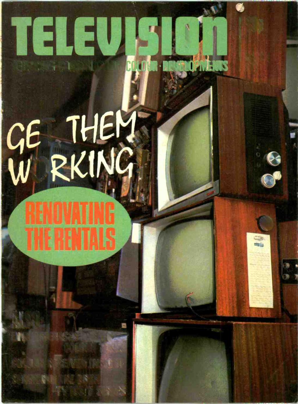
5 195 VOL, s2s2u N20575 SERVICING.CONSTRUCTION.COLOUR.DEVELOPMENTS MARCH 1912 FOURTH CHANNEL IF one can judge from the space given to the subject in the national press there is considerable agitation at present for the inauguration of a fourth television channel. Apart from giving the television correspondents something to write about, ITA has added fuel to the fire by publishing a 24 -page booklet, their "Submission to the Minister of Posts and Telecommunications for the establishment of ITV -2." The arguments have raged for and against giving the ITA the go-ahead to start their "alternative" service. Some have urged that the fourth channel should go to the present ITA programme contractors. Others have suggested a system in which minority interests can operate under the aegis of the ITA without being dependent on the major programme contractors. Another idea is for a form of community television system, giving the regions the freedom to opt out of the network programme and involving large numbers of low -powered local stations. Then there are schemes for an educational service, for wired systems and so forth. There is no doubt at all that the Minister for Posts and Telecommunications, Mr. Christopher Chataway, is being bombarded with proposals, plans and ideas. But it seems to us that there are two rather important factors in this apparent anxiety to allocate quickly the fourth television channel to its ultimate operatives. First, most of the vigorous lobbying seems to come from individuals and organisations who would have vested interests in the fate of the spare channel. Secondly, there appears to be little agitation (rather, apathy) from those who will be most affected by the end result of any decision-the viewers. One could mount a strong case for or against any of the current proposals, but it is significant that there is no clamour from viewers to fill the vacant hole. It is all very well to say "we have a spare channel, let's use it," but quite another to find a natural contender who automatically fills one of those long -felt wants we hear about. Let us hope therefore that the Minister will think very hard indeed before signing away this priceless channel-a public asset after all-to any service except one honestly and urgently required in the public interest. For our money nothing so far suggested meets these requirements and until it does we are perfectly happy to have a spare push-button on our tuner. W. N. STEVENS, Editor THIS MONTH Teletopics 196 Renovating the Rentals-Part 1-Ferguson line Models by Caleb Bradley, B.Sc. 198 Long -Distance Television by Roger Bunney 202 Letters 204 A Closer Look at PAL-Part 4-More Colour Errors by E. J. Hoare 205 Colour Receiver Circuits-Reference Oscillator Circuits by Gordon J. King 212 Servicing Television Receivers-Bush TV103/ TV105 Series by L. Lawry -Johns 215 Receiving ORTF-Postscript by Roger Bunney 218 Colour Receiver Insight -1 -ITT/KB CVC5 Chassis by S. George 220 Service Notebook by G. R. Wilding 224 ICs for Television-Part 6-Mullard TBA Series -1 by K. T. Wilson 225 Bilsdale West Moor UHF Service Area Map 228 Line Timebases for 110 Colour Tubes by J. W. Thompson, B.Sc. 229 Your Problems Solved Test Case 111 THE NEXT ISSUE DATED APRIL WILL BE PUBLISHED MARCH Cover: Our cover photograph this month was taken by courtesy of Telecare Ltd., Tottenham, London. IPC Magazines Limited Copyright in all drawings, photographs and articles published in ''TELEVISION" is fully protected and reproduction or imitation in whole or in part is expressly forbidden. All reasonable precautions are taken by "TELEVISION" to ensure that the advice and data given to readers are reliable. We cannot however guarantee it and we cannot accept legal responsibility for it. Prices are those current as we go to press. All correspondence intended for the Editor should be addressed to Fleetway House, Farringdon Street, London, EC4A 4AD. Address correspondence regarding advertisements to Advertisement Manager, Fleetway House, Farringdon Street, London, EC4A 4AD.


6 1 96 LOOKING TO THE FUTURE Dr. Walter Bruch of Telefunken, inventor of the PAL colour system, speaking to the Royal Television Society in London has predicted the end of monochrome television after Dr. Bruch believes that in ten years' time colour will have taken over completely. Like many others Dr. Bruch does not see an early end to the shadowmask tube and believes it will be years before a flat solid-state display device will be a practical alternative. Dr. Bruch predicts that most TV set circuitry will be packed into a couple of i.c.s well before then. Rank -Bush -Murphy's TV development manager Walter Halliday has on the other hand predicted flatscreen TV sets suitable for wall hanging by the end of the present decade. This prediction _follows the news that sets witih 110 deflection angle shadowmask tubes are expected to be introduced next year. Some of the problems of deflection and convergence with 110 colour tubes are described in an article later in this issue: the increased scanning power required by a 110 colour tube in comparison to a 90 tube is of the order of 2.2 : 1. PAL DECODING: ANOTHER SYSTEM The PAL system is not only,robust, giving us very reliable colour reception as E. J. Hoare has been pointing out in his present series, but also seems to be capable of a great variety of approaches to decoding. Readers will by now be familiar with the usual system (see for example Colour Receiver Circuits, October 1971), the Sony approach (also described in our October 1971 issue) and the subtle variations on the usual technique used by RBM (see ICs for Television, November 1971). Other approaches that have not so far been used in practice have come to our notice but now comes another that is in use-in the Teleton Model VX1110 colour receiver now being distributed in the UK and produced by the General Corporation of Japan. The new approach is based on patented circuits originally developed by GC's technical director Yasumasa Sugihara for the Color- Chroma Signal 169 Gated Jur..1 amp 4.43MHz subcarrier regenerator 4-44MHz subcarrier _41 regenerator t Varicap phase modulator 9 hilt Line frequency sawtooth modulating waveform Fig. 7: GC's approach o PAL decoding. U reference signal Switched V reference signal Integrator Line pulse net system intended for use with single -gun tubes. The heart of the GC system-where it differs from the usual approach-is shown in Fig. 1. As in the Sony system two subcarrier regenerator circuits (instead of the usual one) are used. Here the similarities end however. In the GC decoder one sub - carrier regenerator operates at the normal 4.43MHz subcarrier frequency, providing the U reference signal for the U demodulator, while the other operates at 4.43MHz plus 7.8kHz (half line frequency) which is roughly 4.44MHz. As the bursts alternate ±45 from line to line in the PAL system 4.44MHz is one of the sidebands of the burst signal present in a PAL transmission and can be selected by a suitably selective circuit. Now if the relationship between 4.43MHz and 4.44MHz is carefully examined we find that during the period of two lines there is exactly one extra cycle of subcarrier present at 4.44MHz, i.e. we get an advance of one half cycle each line period relative to 4.43MHz. What is happening is that the 4.44MHz carrier completes an extra rotation of 360 every two lines: so if we can alternately retard this rotation for a line and then during the flyback period let the carrier advance to the position it would otherwise by then have reached we will get on alternate lines a signal which is ±90 relative to 4.43MHz. And this is of course the switched V reference signal that is required for correct demodulation of the PAL alternate line +V signal. Retarding and advancing the 4.44MHz carrier by the correct amount is achieved by modulating it with a line frequency sawtooth waveform. This is obtained by integrating the line flyback pulse and using this in a varicap phase -modulator circuit. Ident? V synchronisation is simply achieved by locking the V subcarrier regenerator to either the + or -7.8kHz burst sideband. For our next trick...! TV FIRES: A WARNING Mains -operated radio and television sets can cause fires as we should all be well aware. Now the Fire Protection Association has appealed to the BBC and ITA asking them to broadcast fire safety warnings every night in an effort to help reduce the 1,500 fires which it says occur every year in radio and television sets. As the FPA says, the simplest and most effective precaution is to switch off the set and then unplug the set from the wall socket after use. UHF COVERAGE EXTENDS The service available from the u.h.f. relay stations is being rapidly extended by both the BBC and ITA.
7 197 BBC -1 and BBC -2 are now being transmitted by the Lancaster relay on channels 31 and 27 respectively (vertical polarisation, receiving aerial group A). BBC -1 is now being transmitted from Skipton on channel 39 (vertical polarisation, receiving aerial group B), Salisbury on channel 57 (vertical polarisation, receiving aerial group C) and Halifax on channel 21 (vertical polarisation, receiving aerial group A). In addition the BBC announces that BBC -1 from Sudbury is now being transmitted at full power, all three services from this station now operating at the same e.r.p. The latest ITA relay stations to come into operation are Rhondda, South Wales, carrying HTV- Wales programmes on channel 23 (vertical polarisation, receiving aerial group A), High Wycombe carrying the London area programmes on channel 59 (vertical polarisation, receiving aerial group C) and Sheffield carrying Yorkshire Television programmes on channel 24 (vertical polarisation, receiving aerial group A). For experimental periods recently the BBC and ITA London area transmitters have been using an electronic test "card" instead of the usual test card F. BBC -1 transmitters radiated the electronically - generated colour picture signal from January 24th - 28th, BBC -2 transmitters from January 31st to February 4th and the ITA transmitters from February 7-11th. TELEPLAYERS Vidicord have introduced a teleplayer, the "Projector 8", which uses a TV camera tube to scan pictures on Kodak cartridges or spool -to -spool film and can supply a monochrome output to any number of TV screens. The teleplayer can also be used to project the film live with the camera tube removed from its mounting. It can be programmed to return to a preset spot and repeat the programme indefinitely. The recommended retail price is 360. Meanwhile, what is going on with the much talked about EVR system? CBS, who invented the system, have withdrawn from the manufacturing and marketing side but "will retain an investment in the EVR Partnership by way of debt investment and the licensing of current and future patents and developments in the EVR field" and also distribution and exploitation rights in the USA and Canada. This does not look as though CBS is exactly brim full of confidence in the economic prospects of its brainchild. We understand that with all the new techniques involved it has not proved easy to get an EVR teleplayer production line into smooth operation. TRADE NOTES The 1972 RTRA conference is to be held at the Palace Court Hotel, Bournemouth, from April 23rd - 26th. Sets, both colour and monochrome, seem to be flooding in from all quarters to meet the current shortage. We understand that the Italian Indesit concern is shipping in some 10,000 sets, a mixture of 12in. portables and 24in. table models. Decca say their 12in. mains/battery portable is now available to the trade. The set has been given the name "Gypsy" and is intended to sell at around 66. Two new colour sets have been introduced by Ekco, both 22in. single -standard models fitted with the 693 chassis. They are the CTI20 at and the CT 122 at A new portable with a difference is the JVC Nivico Videosphere Model The chassis and tube are mounted in a swivel -based sphere which can be rotated in any direction for convenient viewing. The set is fitted with a 9in. tube, built-in rod aerial and earphone jack and weighs 11 ilb. It is distributed by Denham & Morley (Overseas) Ltd. AERIALS There are new aerials from Antiference and Telecraft. From Antiference comes an addition to their Hi -Gain range: the HG7080 is a stacked version of their HG3540 and is equivalent to a 4 x 18 element Yagi. It is available for channel groups A, B and C/D and the recommended price is The new Telecraft aerial is the Space Master, a continental - style aerial with H -type stacked director assemblies. The director and reflector assemblies fold flat for storage but click permanently into position for installation. There are three models, the Master 12 with 5 director assemblies at 2.70, the Master 18 with 8 director assemblies at 3.25 and the Master 34 with 16 director assemblies at RTS NEWS Aubrey Buxton, an executive director of Anglia Television, has been elected a Vice -President of the Royal Television Society. Amongst the subjects at the Society's meetings during the first half of this year that may be of interest to readers are "TV and Chips -Integrated Circuits for TV Receivers" on March 16th, "Single -Tube Colour Cameras" on June 1st and the "Teldec Video Disc" on June 29th. These meetings will be held at the Conference Suite, ITA, 70 Brompton Road, London SW3, commencing at 7 p.m. and non-members are admitted on presentation of a signed ticket obtainable from the Society at 166 Shaftesbury Avenue, London WC2H 8JH. ENT PROTECTION The e.h.t. over -voltage circuit used in the RBM single - standard colour chassis is to be modified to give additional protection. The present circuit comes into operation, shunting the line oscillator coil and thus removing the line drive, when the e.h.t. rises to a dangerous level as a result of a fault on the power board causing the h.t. line to rise above 200V. The line drive is removed until the fault condition is rectified. Increased h.t. is not however the only possible cause of e.h.t. over -voltage and to take other possibilities into account the neon cut-out on future timebase panels will come into operation when the line flyback pulses exceed a certain level. A diode will be used to monitor the peak flyback pulse and provide a rectified output to operate the cut-out when the pulse exceeds a certain value. LOCAL TV OVER CABLES Greenwich Cablevision are seeking a one-year experimental licence to provide locally -originated programmes over the cable TV system they operate in Greenwich. Permission from the Ministry of Posts and Telecommunications is necessary to provide local programmes other than educational services over piped networks.


. They are very deep sets since the curved ply cabinet goes back about as far as the tube base and they are also very heavy.")

 V7, V8, the boost reservoir capacitor C124 and the screen feed resistor R136.")

8 198 Renovating the RENTALS CALEB BRADLEY B. Sc. 0 FERGUSON 405 -LINE MODELS ANYONE armed with some basic servicing ability can find bargains among the thousands of television sets now being sold off by rental companies and available from many sources. The sets include pre -BBC line models, dual -standard 405/625 sets and even, for the bold only, dual -standard colour sets. Virtually all the models which were popular for rental are worth renovating since spares are not expensive and the restored performance can be very good. In this series we will look at some of the stock faults which are regularly found on particular models and are worth putting on record for future servicing. This means that the emphasis is less on the faults which logical servicing would quickly locate and more on the type of fault which is unusual in either its cause or its cure. The over-riding importance however of an ordered, thoughtful servicing approach must not be forgotten and a section at the end of each article will therefore cover some aspect of rental renovation not restricted to any particular model. The Ferguson 405 -line sets described here should be a pushover and are certainly cheap. They have all been around long enough in both rental and private use for their frailties to have become well known. Two good things about a 405 -line set are that it has no standards switch to go wrong, and that in those days they made decent cabinets. Models 3061 (17") and 308T (21") Many of these venerable sets are still in use and with occasional servicing assistance some will doubtless survive their 21st birthdays-in 1977! (assuming 405 transmissions last that long). They are very deep sets since the curved ply cabinet goes back about as far as the tube base and they are also very heavy. Most of their faults are conventional and so need not be mentioned here but one to watch out for is change in value of C123 which supplies line drive from the line blocking oscillator to the line output valve grid-see Fig. 1. This capacitor has been known to drop drastically in value to a few hundred pf; in spite of this the set gamely goes on working but with greatly reduced picture width and brilliance. Of course the conventional causes of this should be vetted first. They are (referring to Fig. 1) V7, V8, the boost reservoir capacitor C124 and the screen feed resistor R136. If C123 and the line oscillator are both o.k. an Avometer on the 100V a.c. range should show at least 15V drive to V7 grid (pin 2). Slow warm up on these and other sets using the PY32 h.t. rectifier, also lack of width and height, point to this valve being in need of replacement. It should be replaced with the better PY33. The h.t. at pin 8 of this valve should be about V. It is not generally known that the picture resolution on these sets can be varied by a clip -ended flying lead on the right-hand side of the chassis-see Fig. 2. This "picture quality adjustment" alters the total h.f. decoupling capacitance in the video output valve (VS PCF80, pentode section) cathode circuit, affecting the fine picture detail. The original Ferguson instruction was that extra h.f. boost might be needed for sharp Sync 47k 50p VS PCF80 (part) Line osc V12 PCF80 Sync sap and Height Vii PCL83 Audio amp and output Field Iln V1G PY32/33 Y11 rectifier lost trap R ,,ra C123 drive Ikp ye PY81 Efficiency diode V7 P181 Line output 2.2h1 TC TC LOPT 124 y HT k CRT first anode Width C125 15k Ikp ine linearity1 1.2k Line scan coils EHT rectifier IC V9 EY86 EHT to CRT 19 Fig. 1: Line output stage, Models 306T and 308T. VI PCC84 RF amp V2 PCF80 Frequency changer field osc VI3 PCL83 field osc and field output V3 EF80 1st vision and sound IF amp Fig. 2: Rear view, Models 306T and 308T. I is.31 V8 PY8I Efficiency diode V7 P181 Line output V9 EY86 EHT rectifier V5 PCF80 Video output and line osc White spot limiter 'Picture quality' adjustment 1015 EB91 Sound and Haien limiters W. EF80 2nd vision IF amp V10 EF80 2nd sound IF amp OKI
9 199 pictures "... in certain areas, particularly Scotland and Wales..."! Here is a tip for dealing with line output transformers which arc over (but are not badly burnt): it applies to many models but is specially relevant to these as it is rarely worthwhile fitting a new line output transformer in them. First brush off all dust and any carbon that has formed, then saturate the area with Holts Damp Start spray for cars (Halfords, etc.). This has saved many 306Ts from oblivion. On sets as old as these it is not unreasonable to boost the c.r.t. heater current to prolong decaying emission. Do this by wiring a 5k12 low wirewound resistor from the mains dropper to the non -earthed heater pin on the c.r.t. base, making allowance for the fact that the resistor will run hot. Vertical striations at the left of the picture and fading out towards the centre have been found to be caused by either the resistor across the line linearity control (1.21a2) going open -circuit or a fractured line output transformer core. Models 406T (17") and 408T (21") These sets are more advanced, having a printed board and a Fireball v.h.f. tuner. There are numerous cabinet variations using the same chassis (Fig. 3) and also versions equipped with v.h.f./f.m. radio. These include the 416T, 436T, HMV 1870, Marconiphone VT157 (all l7in.); and the 438T, HMV 1874 and Marconiphone VT160 (21in.). There is a closed -loop sleeve under the scan coils for line linearity adjustment : its notch should be at the same angle as the e.h.t. connector and there should, taped to the top of the chassis, be a template which gives the correct spacing of the sleeve from the tube flare: Otherwise just slide the sleeve in or out for the best test card display. If the pilot lamp behind the tuner knob should go open -circuit the set will go on working but the valve and c.r.t. heater currents will be below optimum. These sets have the unusual feature (for monchrome sets) of a shunt e.h.t. regulator. It consists of an adjustable Metrosil v.d.r. (voltage dependent resistor) Zl-see Fig. 4(a)-in series with R132. The sliding clip on the Metrosil should be adjusted for 7V at the test point with the brightness turned down (use an Avometer on the 10V range). If in doubt, cut it outthe set will still work. There is another smaller Metro V13 PY32/33 HT rectifier V7 PL36 Line output Field lin V2 PCF80 Freq changer VI PCC84 RF amp V8 PY81 Efficiency diode Height ZI EHT shunt regulator V5 PCL84 Video output and width V9 EY86 EHT rectifier field osc V6 PCF80 Lin* osc and sync sep V4 EF80 nd vision IF amp V12 PCL82 field our and field output Vi) PCL82 Audio amp and output V3 EF80 Ist vision and sound IF amp VIO EF80 2nd sound IF amp Fig. 3: Rear view, Models 406T and 408T. sil across the field output transformer primary for height stabilisation. This series of sets is capable of a spectacular burnup in the video output stage-see Fig. 4(b). What sets it off is a short between the control and screen grids of the PCL84. This causes excessive currents in the divider chain of resistors which hold the screen grid and the cathode at the correct potentials. The 471a2 resistor may go up in smoke completely and C58 may be damaged. The hard -learnt lesson is that the valve must be replaced at the same time as these components or the trouble will happen again. Another trouble with this stage is that some of the video chokes go open -circuit with monotonous regularity. When L4I or L42 go open -circuit all picture is lost and the valve goes unstable due to its open -circuit grid. When L43 goes open -circuit a thin streaky unlockable picture still just gets through. In all cases the picture returns but with reduced definition when the offending choke is shorted across. Usually the choke can be taken out and repaired. The mains dropper troubles described at the end of this article are rife on these sets in which the dropper runs hot enough for its soldered connections to deteriorate. Cramping or foldover at the bottom of the picture may seem to be cured by replacing the field output valve (V12 PCL82) but always check its cathode resistor (47012) and the decoupling electrolytic (100p.F) or the trouble may recur. The cathode should run at 14-15V. In cases of poor field lock replace the field sync feed diode W11 with an 0A91. "Scatchy" tuner switching can often be cured by IC TC V7 P4.36 Line output V8 PY81 Efficiency diode LOP' (part) 6461 HT 200V EHT rectifier EHT to CRT 1,9 10 Z1 (adjustable) Test point (see test) R k 1000A max la) EHT shunt regulator HT Video detector 0A70 spme. 6.8M 470k 1kp 1 47ki L39 (1611),r)Pr 20p 0A79 'Ay Fig. 4: E.H.T. circuit (a) and video output stage (b), Models 4061 and 408T. D.C. resistances are approximate. LLO 2 A 5.6k To sync separator p HT 200V DE

10 200 cleaning the silver contacts on the Fireball tuner disc. The tuner cover is a spring fit and the disc is held on by a central nut at the back. Do not disturb the coils on the disc or the spring contacts inside the tuner. Models 506T, 546T (17") and 508T (21") With these models we enter the TV "boom age" of slimline sets made possible by 110 angle deflection tubes. The video output stage is very similar to that of the 406T series so similar faults occur except that L43 is absent (good riddance) and its h.f. peaking function is taken over by a 1.2kpF capacitor from the pentode's cathode to chassis. This is more reliable but has been known to go short-circuit causing a low - contrast picture with clipping of the whites-like when the vision interference limiter is mis-set. Unstable height can be caused by poor rivet connections on the height control. Prodding its terminals will reveal if this is so. Otherwise the field troubles are similar to those of the 406T series, the important point to check being the cathode of the field output pentode (pin 2, I5V normal) which is connected to chassis via 330n and 100,uF. Access to the underside of the i.f. board seems impossible until you see that by removing two screws below its rear edge it can be lifted clear of the chassis, turned over and latched on again. The chassis layout is shown in Fig. 5. General Fault: The No -Glow Set This is the set where absolutely nothing happens on plugging in, not even a glow from the c.r.t. or valve heaters. With this set you can make progress with nothing more than a neon screwdriver since the fault is a break in the heater chain-see Fig. 6. But before touching any part of the chassis check that it is connected to mains neutral, not live. The history of an ex -rental set is unknown so do not rely on the red - black coding of the mains lead. Also never rely on the on/off switch alone to isolate the set from the mains: this is always a double -pole switch but one pole often fails and it may have been shorted across as a makeshift cure. Also note that if the set has a silicon or selenium h.t. rectifier there will be h.t. to all circuits even with the heater chain broken. Heater chains vary from model to model but almost all have the basic features shown in Fig. 6. The c.r.t. heater is usually the closest to chassis (except for some BRC chassis) so that its heater -cathode insulation will not be unduly strained on negative swings of the mains. The order of the valve heaters varies, but the r.f. and i.f. valve heaters are generally together and have small decoupling capacitors. The dropper resistor is a large wirewound component with adjustable tappings for different mains voltages and is a regular offender. Sections often burn Fig. 6 (below): Typical heater circuit. V12 PCL82 Audio amp and output V2 PC F80 Freq changer V1 PCC8L RF amp Timebase board 1671 IF board V10 EY 86 EHT rectifier V3 EF85 1st vision and sound IF amp V14 PY32/33 HT rectifier V11 EF80 2nd sound IF amp IF board (front) Local/distant Vision VL interference EF80 limiter 2nd vis IF amp Timebase board (front) V13 PCLB2 Field Field osc lin and output Fig. 5: Chassis layout, 506T series. V5 PCL84 Video output and sync sep V6 E B91 Sound and vis limiters V7 ECC82 Line osc and field osc V8 PYI31 Efficiency diode V9 PL81 Line output Horiz lock Height Vert lock out, breaking the heater chain. A neon tester will reveal the position of the break if this is not obvious, since it should light when touched to any of the tags on the dropper. It is usually easier to bridge an open - circuit section with a wirewound resistor of adequate wattage (the Radiospares replacement dropper sections are excellent service components) than to replace the whole dropper. Wire the new component securely to the dropper tags rather than relying on the solder for support since the operating temparature is often high enough to soften the solder. If in doubt about the value of a section to be replaced-or the correct tag setting for a particular mains voltage-the rule is that the current in the heater chain should be 300mA (as a quick check on this there should be 6.3V across the c.r.t. heater). Obtain the correct heater voltages of all the valves in the chain from a valve data book, add them together and subtract the resultant sum from the mains voltage in order to find the voltage which must be dropped. Ohm's law (R=V II) then gives the total dropper resistance needed. The wattage of each resistor in the chain should be at least 3 its value in ohms. The thermistor TH1 may be present in the chain. It has a high resistance when the set is switched on from cold, so that excessive current does not flow in the cold heaters, but quickly warms up and settles at a lower resistance. Since a thermistor prolongs the lives of the valves and c.r.t. it is worth incorporating one in a set not so equipped. Thermistors generally give little trouble although sometimes the end connections break away. The following table gives characteristics of some common types for heater chains. The normal working resistance is the "hot" figure. Equivalent types TH1, VA1015 TH2, VA1005, CZ1 TH3. VA1026 Cold resistance 930n 400n Hot resistance (at 300mA) 42t 44n 28t2 L N Mains Mains fuse on/off 0 Dropper resistor 240V 230V 220V -t-n/v%,-*-naatmai-o-'\aar-m-i 1 240V 230V 220V 0-1 TIII RF and IF valves lk p 1kp 1kp 1kp H7 CRT 1 8


 CME1906 (T) 7405A (M) A47-I3W (T) MVV5220 (M) C2I /AF (M) CMEI908 (M) 7406A (M) A47-I4W (M) MW53/80 (M) C2I /KM (M) CME2I01 (M) 7502A (M) A47-17W (P) AW47-97 (M) C21/5M (M) CME2104 (M)")
11 meg./i LAWSON BRAND NEW TELEVISION TUBES SPECIFICATION: The Lawson range of new television tubes are designed to give superb performance, coupled with maximum reliability and very long life. All tubes are the products of Britain's major C.R.T. manufacturers, and each tube is an exact replacement. Tubes are produced to the original specifications but incorporate the very latest design improvements such as: High Brightness Maximum Contrast Silver Activated Screens, Micro -Fine Aluminising, Precision Aligned Gun Jigging, together with Ultra Hard R.F. High Vacuum Techniques. [ DIRECT REPLACEMENTS FOR MULLARD-MAZDA BRIMAR GEC, ETC. A21 -II (P) AW47-91 (M) C19, AK (M) CME1902 (MI 173K (M) A28-14W (P) MW43-64 (M) C21/IA (M) CMEI903 (M) 212K (M) A31-18W (P) MW43-69 (M) C2I,7A (M) CMEI905 (MI 7205A (M) A47 -I 1VV (P) MW43-80 (M) C2I /AA (M) CME1906 (T) 7405A (M) A47-I3W (T) MVV5220 (M) C2I /AF (M) CMEI908 (M) 7406A (M) A47-I4W (M) MW53/80 (M) C2I /KM (M) CME2I01 (M) 7502A (M) A47-17W (P) AW47-97 (M) C21/5M (M) CME2104 (M) 7503A (MI A47-I8W (P) AVV53-80 (M) C23/7A (M) CME230I (MI 7504A (M) A47-26W (P) AW53-88 (M) C23/I0 (11) CME2302 (M) 7601A (M) A59 -II (P) AVV53-89 (M) C23/AK (M) CME2303 (M) 7701A (M) A59- I2W (P) AW59-90 (M) CME1101 (P) CME2305 (P) CRM 121 (M) A59- I3W (T) AW59-91 (M) CMEI201 (P) CME2306 (T) MW3I-74 (M) A59-I4W (T) CI7IIA (M) CMEI402 (VI) CME2308 (M) A50-120W,R A59-I5W (M) C17,5A (M) CMEI601 (P) CRM 172 (M) (P1 A59-14W (T) C17/7A (M) CME 1602 (P) CRM 173 (MI AW36-80 (M) CI7 AA (M) CMEI702 (M) CRM2I 2 (M) AW43-80 (M) C17/AF (M) CMEI703 (M) CRM2I I (M) AW43-88 (M) C17/FM (M) CMEI705 (M) 235P4 (MI AW43-89 (M) C17/5M (M) CME1706 (M) 171K (M) AW47190(M) CI9110AP (T) CMEI901 (M) 172K (M) LAWSON TUBES 18 CHURCHDOWN ROAD, MALVERN, WORCS. Malvern 2100 YEARS' GUARANTEE FULL TUBE FITTING 2 INSTRUCTIONS Tubes are despatched day of order by passenger train, road or goods taking far too long for customers satisfaction. REBUILT TUBES LAWSON "RED LABEL" CRTS are particularly useful where cost is a vital factor, such as in older sets or rental use. Lawson "Red Label" CRTS are completely rebuilt from selected glass, are direct replacements and guaranteed for two years. Brand New Tubes Red Label Rebuilt Carr. Ins. 17" (M) 625 [4"97 12" - 19" 19" (M) E p 21" (M) E " (M) [ " Twin Panel (T) L10.25 N.A. 20" - 23' 23" Twin Panel (T) El 5.50 N.A. > 19" Panorama (P) E9-38 E " Panorama (P) L10.50 a.50 23" Panorama (P) Ell 95 E875 J 16" Panorama (P) 8.50 Replacement only E..H.T 50p CHILTMEAD 1 9 & Tel. Reading No.. for each, Arthur Reading most P & P sets 15p LTD. Road TV's 19" NOW TWO YEARS GUARANTEE ALL MODELS 405/625: 19" 25.95, 23" FREE CATALOGUE DAILY l'emonstrations FOR PERSONAL SHOPPERS carr WINDINGSCOMPONENTS MUST BE CLEARED Transistor Radio Co...: 25p each. Size 9i- x 6y x Co. Post 15P Speakers: 3Sp. 21" BO. Brand new. Post 15p. Press Button Switching unit. 4 Banks 2.5p 6 Banks 35p P & P 5I, Precision Tape Motors: LI ,250V. Famous German manufacturer. Post 20p. Transistor Gang Cond : 20p. Miniature AM. Post free. Modern Gong Cond : 30p. AM FM or AM only 20p. Post 10p. Transistors 13p each. Post free. ACI26, AC128, AFI 14, AFI 17. 0C45, 0071, 0031, 0031D. Volvos ILLSO 30p. Only stock in the country. Pots.: 259 each. Post Sp. D,SW 500,500 Ka. D SW KS2. 05W 1 Ka. SSW 500,500 Ka. S'SVV 500,1 meg.... COLOUR TV's 25" ' E A selection of recent years models. U.K. manufacture. Regret personal shoppers only. TV TUBES REBUILT GUARANTEED 2 YEARS 14" 3.95; 21" & 23^ Exchange Bowls giv 17" & 19" 5.95; 6.45 carr. 55p. DUKE & CO. (LONDON) LTD. 621(3 ROMFORD ROAD, MANOR PARK, E.12 Phone Stamp for Free List


12 202 (-1 DECEMBER has been a strangely active month. During the first and second weeks a settled anticyclonic weather system gave enhanced tropospheric reception over a wide area. One feature of this system was the ducting effects that occurred on several occasions. Our East Anglian friends report that this effect produced u.h.f. signals from Switzerland on a number of channels when little else was being received. Indeed we understand that one person received no less than eight Swiss u.h.f. transmitters. Graham Deaves also reports reception of an East German ch.e34 transmitter carrying an identification slide "Greifswald". From our current transmitter list this seems most likely to have originated from Rostok. If anyone has up-to-date information on the DFF u.h.f. network we would be pleased to hear as we have had some difficulty in obtaining accurate lists. An encouraging sign for the next Sporadic E season has been the increase of signals via this propagation mode. Indeed there have been a number of minor openings logged, notably on the 19th when prolonged signals were received during the morning and afternoon. This is a good sign as midwinter openings were common in the active years of the early 1960s so I feel we can look forward to a 1972 Sp.E season with signals greatly improved over those of recent years. My own log for the period under review is as follows : 1/12/71 DFF (East Germany) E4 (MS-meteor shower). 4/12/71 NOS (Holland) E4 (tropstropospheric). 5/12/71 TVP (Poland) RI (MS); NOS E4. FOE TELEVISION 6/12/71 WG (West Germany) E4; DFF E4 (both MS). 7/ 12 / 71 Improved tropospherics- ORTF etc. 9/12/71 DFF E4 (MS); NOS E4. 11 /12 /71 SR (Sweden) E2 (MS/Sp.E). 13/12/71 CT (Czechoslovakia) RI (MS). 14/12/71 SR E2; CT RI; ORF (Austria) E2a (all MS); also Caen ch.f2 trops on line tests. 16/12/71 WG E2 (MS); unidentified signals at 1720 ch.r1 via Sp.E together with the familiar RTTY "whistling". Signals faded at 1730 although I feel Sp.E activity may have been experienced during the afternoon. 17/12/71 NRK (Norway) E3 (MS); SR E3 (MS). 18/12/71 WG E4 (MS); SR E2-long duration Sp.E signals. 19/12/71 SR E2 (MS); BRT (Belgium) E2 (trops); unidentified Sp.E signals at 1535 ch.r1-end of a Sp.E opening during the morning (see correspondents' letters). 20/12/71 SR E2 (MS). 22/12/71 SR E2, E3; WG E2 (all MS); unidentified Sp.E signals ch.r1 at 1825-long duration. 23/12/71 SR E2 (Sp.E). 24/12/71 DFF E4 (MS). 28/12/71 SR E2 (MS); unidentified Sp.E signals at 0910 ch.e4. 29/12/71 SR E3 (MS); BRT E2 (trops). 30/12/71 SR E2 (MS). 31/12/71 SR E2 (MS). From December 10th I moved location from Romsey to the Southampton ROGER BUNNEY area. For the present I am operating with a temporary aerial system (actually the omnidirectional X array featured in PRACTICAL TELEVISION July 1969) whilst the various problems on the domestic front are being sorted out. When the warmer weather arrives plans will be put into operation for a more substantial array. From initial observations the location appears to be an improvement despite the increased signal strength from the "local" on ch. B3 some 14 miles away at 100kW. One problem that is being investigated is interference on ch.e4 from an r.f. welder thought to be some 2+ miles distant on the far side of Southampton Water. This gives some 3µV peaking to 12pV on ch.e4 during factory hours, as measured on separate signal -strength meters. Fortunately the GPO were able to observe the interference when they called and an end to the problem is anxiously awaited in the near future. Sunspots: Smoothed predictions for the next six months are as follows: December 49, January 47, February 45, March 43, April 42, May 41. The actual mean value for November 1971 showed an increase to Information courtesy Swiss Federal Observatory. News Items Albania: The big news this month is that Albania is operating a transmitter within the OIRT Band II TV range. This means that given ideal conditions Albania will now be possible via Sp.E. Michele Dolci reports that his contact at Brindisi is receiving signals from a new Albanian Band II transmitter at reasonable strength. The test card and Main Bulgarian news caption PO CBETA N Y HAC. The letters rotate around the globe. Courtesy OIRT Prague. Radio Bremen test card. Courtesy P. D. van der Kramer.


.")

13 203 DATA PANEL 8-2nd series inni CHAIN goo Ufa f 111 France: The test card for both chains is similar, with an identification below the circle to indicate the chain. At present the lest card above left is used by both chains though at times the alternative version with the horse may be used. The second chain colour card is shown below , alli I I8 IllIlI French second chain colour card. Standard pattern: EBU colour test chart. Photographs this month courtesy of Garry Smith and Michele Dolci. programmes are different from those radiated by other Albanian stations. We do riot know the exact channel in use but feel it may be ch.r4 as the signals are being received on an Italian receiver with I presume coils for Italian channels. The only Band II Italian channel is ch.ic with 82.25MHz vision which is the nearest frequency to ch.r4 vision at 85-25MHz. We have been promised photographs of the test card and as soon as these arrive we will print them ready for the coming season. West Germany: Graham Deaves reports that Sudwestfunk have changed the identification on their test card from "Sudwestfunk" and "Sudwest 3" to "SWF Band 1" and "SWF Band 3" for the first and third networks respectively. The Bayerischer Rundfunk third network test card now carries the identification "BR Munchen". The ZDF network test card has been noted at times to carry the identification "ZDF". Switzerland: We understand that the test card carrying the identification letter L has been received with an Italian language programme. This card originates from the Lugano studio centre. In this month's Data Panel we are featuring an EBU colour pattern which is currently in use by both Switzerland and Italy. A Correction In the January 1972 column we mentioned that two new unlisted West German transmitters were in operation (in "Our Correspondents" section). I have subsequently discovered that the caption "Unter Brechung" indicates a pause or intermission! This is often used during periods when there is a breakdown or interruption to the main programme coming to the transmitter. We apologise if this error has caused confusion and appreciate the interest of a number of readers who contacted us to point out the error. Lightning -flash Propagation An interesting mode of propagation has recently been brought to our notice by the WTFDA TV -DX organisation of PO Box 5001, Milwaukee, Wis., USA. Apparently there has been some activity in connection with lightning flashes. Such a flash can produce localised ionisation sufficient to reflect signals over several hundred miles at both v.h.f. and u.h.f. Such lightning flashes can give short bursts of signal (not unlike the more conventional Meteor Shower bursts) and there have been instances of signal reflection upwards of 10 seconds. Such reception is more likely to occur during severe electrical storms. The article indicates that reception may be possible from stations some 500 miles away. Rod Luoma of Detroit reported reception of WFLD-32 Chicago (Ch.A32) in June 1968 at a distance of 250 miles during a severe electrical storm to the West. The station was observed "during lightning strokes, apparently due to ionisation of the air around the charge, there being no signals between strokes". Certain v.h.f. frequencies were also affected. The WTFDA go on to say that the storm may not necessarily be at the midpoint between yourself and the transmitter, nor
14 204 indeed in the true direction. It certainly appears that this may be a field worth further investigation as there may be a connection with Sp.E ionisation : we have all noted the tendency at times for enhanced Sp.E during thundery weather. A word of warning however: if the storm is overhead do not continue to operate the receiver! Postbag We have received a large postbag during December including a letter from our old friend A. Papaeftychiou of Palouriotissa, Cyprus. He has been noting various receptions from his part of Europe including a certain amount of Sp.E in early November. Of more interest to F2 enthusiasts is the news that during the last week of October he received the Rhodesian transmitter at Gwelo ch.e2 with the familiar checkerboard. Signals ranged from "normal" to the more characteristic fluttering and multiple -image type. It appears that sighals were received via the daytime F2 layer and the evening/sunset Trans -Equatorial skip modes. Mark Tracy from his Newquay, Cornwall, home has received excellent signals from Radio Telefis Eireann. Signals were noted on both ch.b7 (405 lines) and ch.h (625 lines) from the Dublin transmitter. The drawing of the test card enclosed with Mark's letter indicates an alternative to that recently featured in our Data Panel. As soon as have a photograph of the alternative type it will be included as a supplement to our main Panel. J. Boswell of Hornsey, London N8 has been busy with his colour receiver and a long letter detailing u.h.f. reception-all colour-has arrived here. The letter covers the period during October when conditions were good and by all accounts his location is extremely good, with 36 stations received in colour definitely identified and with "a lot more W. German stations that could not be positively identified". Unfortunately Mr. Boswell adds that his DXing aerial system collapsed, the mast breaking just above the lashings. One point he thinks will assist some enthusiasts is that the Telefunken test card used by NDR, WDR, etc., often carries the initial of the transmitter at the centre lower frame, e.g. "N" indicating Nordhelle. Finally this month Frank Smales of Pontefract, feeling a little better and encouraged with recent conditions, has sent us a letter telling of the recent Sp.E opening on December 19th. During this opening-lasting from he logged USSR RI, 2; DFF E4; RAI (Italy) IA; NRK E4 and Iceland E4. Interesting to note a similar observation to my comment earlier regarding Wintertime openings: Frank notes that his last December Sp.E opening was on December 1 1 th, His final comment about the more recent opening-"what excitement"! LETTERS READERS' HINTS After replacing the U25 e.h.t. rectifier in the oil - filled line output transformer and fitting a new tube and rectifiers a venerable Murphy V280C now works very well indeed. The 2V 0.2A heater/cathode of the U25 had broken and shorted across to the anode, thus giving a.c. instead of the e.h.t. Replacement of the U25 in an oil -filled Murphy line output transformer is thus well worthwhile and can be done by the enthusiast without much trouble-no dealer will take this job on. If the curved -in edge of the transformer can is bent straight with a pair of thin -nosed pliers the transformer assembly can be lifted out of the oil. When soldering the wire leads of the new valve it is important to avoid any solder spikes as corona can occur even in the oil. After replacing the transformer in its can it is only necessary to re -bend the edge of the can gently (to avoid fracturing the metal) with the pliers : a final seal can then be made around the edge with "bath sealant" which sets like plastic rubber.- John J. Widden (Aberdeen). The following faults were experienced with a DER Model 129 but as this set is fitted with the Thorn /BRC 950 chassis readers may find similar trouble on many other models. The DER Model 129 has a motorised tuner and the mechanism is arranged so that during channel changes-when the motor is in operation-a muting switch comes into operation to isolate the sound, video and line stages from the h.t. supply. The switch was not working but although a raster and sound of a kind were present during channel changes the raster brightness was noticeably down. The main fault however was that bad vision distortion occurred when the volume control was advanced, disappearing again when the sound was reduced to minimum. Maximum sound was distorted and the video distortion turned into hum bars at maximum. Since the main smoothing bank had a bulge this was replaced but without improving matters. Next the muting switch was examined and replaced as it was found to be damaged. The faults however were still present. The h.t. was then measured at each contact of the switch. As expected with the switch closed the h.t. was present at both contacts: with the switch open the h.t. was naturally present at one contact-but was also found to be present, although down by about 40V. when the switch was open! The wiring was traced back to the point where it is distributed to the tuner, sound, video and line stages since obviously there was a leak somewhere. The line, video and tuner feeds were disconnected and the leak was not in any of these directions. This left the sound circuit. This was disconnected and the h.t. leak disappeared, the muting switch now working correctly. Clearly the trouble was in the audio circuit. The audio output transformer was disconnected but voltage was still found to be present at the anode pin 6 of the PCL86. The valve was then removed and still the voltage was present. All that remained at the anode pin was the tone correction network-12kn plus 3000pF-and according to the circuit these go back to the top end of the sound output transformer primary-which we had isolated. So where was the voltage coming from? The circuit is shown in Fig. 1(a). Close inspection of the printed wiring however revealed that the tone correction network instead of being connected to the top of the output transformer, goes to pin 3 of the valve as shown at (b). This pin is the screen grid and has 220V on it. We Then discovered a charred 12kn resistor in series with a short-circuit 3000pF capacitor as the tone correction network and all became clear. Other 950 chassis boards we had in stock were then checked and all were found to be printed in this way. -J. S. Anderson (Sheffield). (a) (b) L5E) Fig. 1: J. S. Anderson's h.t. problem. H


15 A CLOSER LOOK AT MORE COLOUR ERRORS LAST month we discussed in some detail the effects of decoding errors caused by incorrect alignment of the delay line matrix circuit and the phases of the reference carriers fed to the two colour -difference demodulators. It soon became clear that the first sign of trouble is usually the presence of hanover blinds and that a delay line PAL decoder in practice very seldom causes hue errors on the picture. If you followed the discussion in detail your understanding of PAL decoding processes should be pretty good and will stand you in good stead when thinking about other PAL decoding matters. It is rather easy to fall into the trap of thinking that if the normal PAL decoding processes are correctly carried out then no chrominance errors will appear on the picture. Unfortunately this is not the case,, and it sometimes causes mild bewilderment when certain critical hues fail to be displayed with the accuracy expected. First of all we blame the accuracy of the grey -scale tracking and when this proves to be correctly adjusted we recheck the purity and perhaps even tickle up the convergence again. If the colour -difference drives can be adjusted we do this too. When all these adjustments are correct there is no point in spending any more time on the problem: the receiver is giving the best performance of which it is capable and the chances are greatly in favour of the colour picture quality being of a high standard. If we are still not completely satisfied however, there are three main likely causes of the deficiency. The producer of the programme may have different ideas of what constitutes correct colour rendering of the scene being televised; the c.r.t. phosphors may display slightly different primary colours compared with those of the studio camera filters and masking; or the trouble may be due to the partial failure of the principle of constant luminance. Display Tube Phosphors It is only possible to get completely accurate reproduction of the original scene if the display -tube phosphors are an exact match of the chromaticities of the primaries at the camera. The situation with regard to 205 the specification of the camera primaries is further complicated by the use of "masking" techniques in which the output of each tube is modified by the addition of a small amount of the outputs of the other two camera tubes. This is too big a subject to discuss here: suffice it to say that the c.r.t. phosphors used deviate slightly from the theoretical optimum in the interest of obtaining maximum light output. Furthermore they have appreciable manufacturing spreads in their characteristics. Thus a small hue error is introduced which is not very significant on its own but does have a cumulative effect when added to other minor deviations. Constant Luminance Principle Constant luminance working is an ideal state of affairs that cannot be achieved under the practical circumstances of normal television transmission and reception. However although the errors are quite substantial thereare some compensating factors present and the quality of the displayed picture is not appreciably impaired. The constant luminance principle is one of those interesting side issues of colour television that many people find difficult to grasp although the principle is quite straightforward. It is simply that the luminance signal should carry only brightness information and the chrominance signal only the colouring information. This means that if the luminance signal of a colour transmission is fed to an ordinary monochrome receiver you should get precisely the same picture as you would from an equivalent monochrome transmission. If on the other hand the colour transmission is fed to a colour receiver the luminance signal should provide the brightness information just as it does on the monochrome receiver and the chrominance signal should add the colouring information that turns the black and white picture into a colour one. You can prove this point quite simply by detuning a colour receiver until the colour killer operates. When the colour is killed the resulting black and white picture should look normal: the luminance carrier of the composite colour transmission appears to be displaying a normal black and white picture. As we said earlier this principle of constant luminance cannot in practice be achieved perfectly so that in point of fact the black and white picture is not completely accurate. It is not panchromatic-to use a photographic term-i.e. areas of highly saturated colour are not reproduced in the exact shades of grey that would be obtained if a monochrome camera was used. What is happening is that part of the luminance (brightness) information in the composite colour signal is being carried by the chrominance signal and so is not available for a black and white display: this constitutes a partial failure of the principle of constant luminance. Since this principle is obviously a sound one as it allows a colour transmission to give a perfect black and white picture on a monochrome receiver, why is it not used: why does it break down? The short and complete answer is "gamma". Gamma Correction The need for gamma (y) correction arises purely and simply because the display device-the c.r.t.-has a non-linear input/output characteristic (or transfer
16 206 V V and VY [ V Fig. 1: How the gamma correction applied at the transmitter (top curve) compensates for the characteristics of the c.r.t. (lower curve). For simplicity it has been assumed that gamma is 2: in practice it is normally in the range characteristic). If a c.r.t. is just and only just cut off and we apply a positive grid voltage V the light output can be expressed as KVY where K is a constant. For a long time y was assumed to be 2.2 and you will find it given as this value in all the textbooks. However all modern c.r.t.s have a y of So in practice the light output is proportional to the cube of the voltage drive. If you double the drive you get 23 = 8 times the light output or thereabouts. Clearly in colour television it is essential to have an overall linear system because varying proportions of red, green, and blue signal voltages are being added and subtracted at various stages of the signal processing. If these voltages are multiplied by a cube law at the end of the chain the proportionality between the red, green and blue channels will be lost and most hues will be seriously distorted. In order to obtain this overall linearity the outputs of the colour camera tubes are gamma corrected to the power 11Y. The camera outputs are V'1Y, the c.r.t. gives VY and overall we get V. See Fig. 1. One of the important though incidental advantages of gamma correction is the improvement in signal-tonoise ratio. It is rather interesting to see how this comes about. If you look at Fig. 1 you will see that the dark greys of the transmitted signal (after gamma correction) are proportionately larger than the peak whites. A peak white signal of say 27 units is transmitted as 3 units (for y = 3) whereas a grey of say only 8 units is transmitted as 2 units. Thus if noise of the same amplitude is added to each part of the signal it will be a smaller proportion of the grey signal than would be the case if no gamma correction was employed: the eye is much more sensitive to noise in grey areas than white ones and a useful improvement in noise performance is obtained. Partial Failure of the Constant Luminance Principle Let us see what happens in practice when a gamma corrected composite colour signal is displayed on a normal monochrome receiver. The luminance signal is derived from the outputs of the three camera tubes (in a three tube camera) in the well known way: Luminance signal (Y) = 0.31V/Y+.59G'/Y W/Y. Now if to start with we assume a mid -grey tone then R = G = B = 0.5. So after gamma correction we get = G'/Y = 13'/Y = A/0.5 = We have assumed y = 2.0 because this makes the arithmetic easy to follow. In practice y = and so in practice any effects that we uncover will be disproportionately greater. We now get Y = 0.3 x x x 0.71 = Neglecting certain special effects the monochrome receiver only "sees" the luminance component of the composite colour signal. It ignores the chrominance information because it is coded in a way that the monochrome receiver cannot understand (except as an interference pattern). If the display tube is assumed to have a gamma of 2.0 (normally nearer 3.0 of course) it will treat the luminance signal Y in a non-linear manner so Y becomes YY = Y2 = = 0.5. We can immediately see from this that if this "colour" signal is displayed on a monochrome receiver we get correct reproduction. If we use a different gamma or a different tone the result is still correct. Note however that a difference in gamma between the transmitter and the receiver will cause an error on the displayed picture. This may of course be done deliberately by the producer in order to obtain a special effect. Let us then take our investigation a stage further: what happens to the coloured parts of a scene when displayed on a monochrome receiver? Supposing we have a moderately saturated pure green field (not very common in practice, except perhaps in a cowboy film!). Then: R = 0, G = 0.5, B = 0. After gamma correction R = 0, G = 0.71, B = O. And Y = 0.3 x x x 0 = 042. When displayed on a monochrome receiver we get YY = y2 = 0422 = Now is this correct or not? What should the correct luminance be? If we had no gamma problems and both the transmitter encoding and the display device were linear, i.e. gamma = 1.0, then the transmitted luminance would be: Y = 0.3 x x x 0 = This is what we ought to get but instead we have Y = which is only 60% of the correct value. If we use a more normal gamma of 3.0 we get only 35 %. Quite clearly a monochrome receiver simply cannot reproduce accurately in black and white the coloured areas of a picture. The colours are reproduced with a low value of luminance, i.e. a darker grey than the sensation of brightness that the eye would receive if it viewed the scene directly. The reproduction is not panchromatic. Now to turn to the behaviour of a colour receiver where we shall see that part of the luminance information is carried by the chrominance channel thus demonstrating the partial failure of the constant luminance principle. Taking the previous example (a moderately saturated pure green field) Y = 042. The colour -difference signals therefore are: (11'JY - Y) = = - 042, (G'/Y - Y) = 0.29 and (13'/Y - Y) = The colour tube displays these colour -difference signals added to the luminance signal, i.e. on red = 0, on green = 0.71 and on blue = 0. Thus of these three signals red and blue are zero and so these two guns are not driven and no red or blue light appears on the screen. The green gun receives 0.71 and if the tube's
17 207 gamma is 2-0 the light output is GT = = 0.5. This is identical to the camera output signal and so both the hue and luminance are correct. Now we saw earlier that the luminance signal Y should have been 0.59 x 0.5 = whereas the displayed luminance was In a colour receiver the total luminance output is correct because the chrominance channel is carrying the balance of the luminance. We can see this quite easily by considering the special case where the display tube gamma is 1.0 and so the transmitted gamma is also 1.0. In other words the television system has linear characteristics. This obeys the constant luminance principle as we saw earlier. The R, G, B and Y parameters now become R = 0, G 0.5 and B = 0. Thus: = 0.3 x x x 0 = 0.295, say 0.3. R -Y = = - 0-3, G -Y = = 0.2 and B -Y = = In the colour receiver these are added to give for red = 0, for green = 0.5 and for blue = 0. Note the difference in values between this and the previous case, where the G -Y signal was larger and compensated for the small luminance (Y) signal to give the correct total of (G - Y) + Y. Effects of Subcarrier Rectification As a result of these simple calculations involving gamma correction and the constant luminance principle we have reached the conclusion that brightness errors occur on monochrome receivers but only in areas corresponding to coloured scenes when a colour signal is actually being displayed. The brightness in these areas is reduced. A colour receiver on the other hand reproduces all parts of the scene correctly, whether black and white or coloured. Now these conclusions are partially incorrect: not because our calculations are wrong but because we have neglected another important contributory factor -subcarrier rectification. This is the process whereby the chrominance subcarrier in the luminance channel is partially rectified by the non-linear characteristics of the c.r.t. to give a d.c. output. This adds to the luminance signal and alters the c.r.t. drive and hence the light output. We saw earlier that most modern display tubes have a gamma of about This is because a c.r.t. is in effect a large triode valve and so has a curved Ia/Vg characteristic as shown in Fig. 2 (a). The value of gamma at any given operating point on the curve is given by the slope of the curve at that point (when plotted on a log scale). The luminance signal arriving at the grid or cathode of the c.r.t. has been gamma corrected to the power '/Y and so the light output at the screen is linear. The chrominance subcarrier on the other hand is added to the signal after gamma correction and so is distorted by the gamma of the c.r.t. to produce a non-linear output. This process is illustrated in Fig. 2 (b). The sub - carrier is applied to the c.r.t. as a sinewave voltage but because the /a/ Vg characteristic is curved the resulting anode (beam) current is as shown distorted. The mean value of this distorted waveform is higher than is the case when no colour is present and the subcarrier falls to zero. Clearly the amount of extra current present depends upon the amplitude of the subcarrier. The light output from the screen of a c.r.t. is proportional to beam current and the presence of a chromin- -V9 sinewave Input Distorted sinew ve output Mean level of output Mean level of Input Fig. 2: (a) Beam current/grid voltage curves for a typical c.r.t. (b) The curved la /Vg characteristic of a c.r.t. causes an increased d.c. component of beam current output due to subcarrier rectification. ance subcarrier causes an extra d.c. component of beam current which means more light. Is this a good thing or a bad thing? On a monochrome receiver the brightness of coloured areas of the picture is too low. We can conclude therefore that the presence of the chrominance subcarrier in the luminance channel is a good thing as it produces extra light output from the c.r.t. and thus compensates for the partial failure of constant luminance. It can be shown that if the subcarrier is present at full amplitude the compensation produced is surprisingly accurate and the final result is quite satisfactory. There is a snag of course, as there nearly always is in such matters. The dot pattern caused by the subcarrier in coloured areas of the picture is rather objectionable. The subjective effect of this is however partially offset by the good resolution resulting from the wide bandwidth of the i.f. and video circuits. In practice it is desirable to compromise a bit and to attenuate the subcarrier by about 3-6dB at the c.r.t. In a colour receiver the situation is rather different. The drive to the c.r.t. is basically correct because the missing luminance information is carried by the chrominance signal. It is therefore undesirable to add an extra luminance component and from this point of view the amplitude of the subcarrier in the luminance channel should clearly be kept as small as possible. Unfortunately although this is easy to do the resulting restricted luminance bandwidth causes an undesirable loss of picture resolution unless an exceedingly narrow notch filter is used. Even then the return of the luminance response just below 5MHz tends to pass rather more noise than extra picture information. Generally speaking it is probably better to tail off the luminance response in the region of the subcarrier so that it is attenuated by about 6dB. If a common luminance and chrominance detector is used this is a convenient approach because the sound carrier at 6MHz has to be attenuated by better than 35dB in order to reduce the visibility of the sound/chrominance beat pattern at = 1.57MHz. The decision on these parameters in practical designs tends to be a matter of opinion because they represent compromises between different subjective effects. Moreover we have not yet considered the other effects resulting from any attenuation of the luminance pass - band in the region of the colour subcarrier. These must be born in mind when choosing the best compromise. In order to reduce cost and complexity it is fairly common practice to use a single i.f. detector for obtaining the luminance and colour subcarrier information from the composite i.f. signal. This is an attractively simple technique which works well in practice but needs
 A sinewave train. (b) Phasor representation of (a). (c) An unmodu/ated carrier \"stopped\" at the instant it reaches its peak, i.e. position 3 in (a).")
18 208 Upper sideband Lower sideband (a) Id) Ib) Reference phase 0' and 360 (a) 11 (c) If) 0. reference phase Fig. 3: Phasor diagrams of a carrier and its double sideband amplitude modulation. (a) A sinewave train. (b) Phasor representation of (a). (c) An unmodu/ated carrier "stopped" at the instant it reaches its peak, i.e. position 3 in (a). (d) The upper, higher -frequency sideband rotates faster than the carrier while the lower, lower -frequency sideband rotates more slowly. (e) It is convenient to regard the carrier as being stationary and to show, as here, the relative movement of the sidebands with respect to the carrier: this is a useful simplification. (1) An idealised curve showing the envelope of the modulated carrier. care in application. This is because if the i.f. passband is attenuated in the region of the colour subcarrierfor the reasons discussed above-the colour subcarrier signal to the decoder will be distorted in the same way. It will become a partially single-sideband signal instead of a full double-sideband one as transmitted. To be in a position to assess the situation as a whole and to decide between the conflicting claims of good picture resolution, colour fidelity, and good colour resolution and transient response we need to know what happens to this distorted chrominance signal. This situation does not arise of course if a separate chrominance detector is used, enabling full doublesideband operation to be achieved without penalty. The luminance response can then be tailored to give the best compromise between luminance resolution and correct amplitude. Unfortunately the extra cost of this approach is significant because it usually involves a complete extra i.f. stage, with two tuned circuits, in order to obtain a chrominance amplitude response which is independent of the luminance one. Sideband Operation We made the point in a previous article that the vector and phasor diagrams that are so freely drawn showing PAL signal components are of dubious validity: or at least that one has to treat them with a certain amount of reserve. This is because they are drawn as single carriers whereas we all know that the carrier has been suppressed at the transmitter! We pointed out that these diagrams are in fact representations of a more complicated state of affairs in which the vectors and phasors are equivalent to the sum of the sideband information. Now it is all very well up to a point to use this simplification and it is certainly convenient for many purposes, but it does tend to hide some important factors that arise when the sidebands are distorted. All the chrominance and luminance information of a PAL signal is carried by the sidebands and the chrominance subcarrier is suppressed at the transmitter without any ill effects because it carries no (6) < Upper sideband,... Lower sideband Carrier of sidebands /..---Resultant of carrier + sidebands Resultant Resultant Fig. 4: A phase -modulated carrier is of constant amplitude but the phase rocks to and fro. An envelope detector therefore cannot "read" the modulation. (a) Sideband phasors for a phase -modulated carrier. (b) The resultant of the carrier plus its sidebands is obtained as shown here. (c) Resultants of the carrier plus the sidebands shown in (a).
19 209 picture information. In the receiver it is reinserted because it is an essential tool in the process of extracting the colour -difference signals by demodulation. (The luminance carrier incidentally has to be transmitted in practical circumstances because of the complications that would arise if it was suppressed in the same way as the chrominance one.) The sidebands of the chrominance subcarrier extend for about ± 1.0MHz each side of the centre frequency of MHz and these are present to some degree in all picture transitions. For large areas of constant hue the sidebands are restricted to about 100kHz because the only information that has to be conveyed are the changes representing line and field sync intervals and blanking. What we wish to find out now are the effects on the PAL chrominance signal of distortion of the amplitude response in the signal channel of the receiver. Typical response curves will give heavy attenuation at the top end of the upper sideband-near the sound carrierand may be sloping in the region of the centre frequency. In order to investigate this kind of situation we must have a clear understanding of the form of a carrier modulated with sidebands, whether a.m. or p.m. Remember that the chrominance subcarrier has both amplitude and phase modulation, changes in amplitude indicating changes in saturation while changes in phase indicate changes of hue. Amplitude- and Phase -Modulated Carriers Readers who waded patiently through the monologue on vector diagrams (and others who didn't need to!) will recall that any train of sinewaves (or cosine waves) can be conveniently represented by a rotating vector. This sweeps through a circle of 360 degrees corresponding to the phase angles of one cycle of the sinewave. Fig. 3 (a) and (b) illustrates this technique. So an unmodulated carrier can be represented by Fig. 3(c) in which it is assumed that the carrier has been "stopped" at one particular instant in time. The angle of the phasor indicates the phase of the carrier at the instant at which it stopped: in this case 90 degrees from a reference phase at 3 o'clock. Now we come to sidebands. A sideband is at a higher frequency (upper sideband) or lower frequency (lower sideband) than the carrier. Hence it will be rotating faster or slower than the carrier. So if we start off, as in Fig. 3(d), with both sidebands in phase with the carrier and then "stop" the signal at successive intervals of time we get the phasor diagrams as shown. These are for amplitude modulation. We know that the carrier is rotating steadily and in order to simplify the diagram it is convenient to redraw it as in Fig. 3(e). This amplitude -modulated carrier is equivalent to a chrominance signal plus the reinserted carrier from a local reference oscillator. Suppose we carry out envelope detection: what is the result? Fig. 3(f) shows the detected output. We can conclude from the phasor diagram of Fig. 3(f) that the amplitude of the demodulated output will vary, but the phase is constant. Remember that this is for the ideal case of full double-sideband operation, and our conclusion confirms what we already know from past experience and learning. Now take the case of a phase -modulated carrier with full double sidebands. The sideband phasors are shown in Fig. 4(a) for several different instants in time, with the carrier stationary. Fig. 4(b) shows how we obtain the resultant of carrier plus its sidebands and Fig. 4(c) Amplitud modulation )b) Phase modulation Fig. 5: In practice there are innumerable sideband components for even the simplest signal. A few arbitrarily selected ones are shown here. the resultant for each of the diagrams of Fig. 4(a). It can be seen that the amplitude of the carrier remains constant but the phase varies in sympathy with the phase of the modulation that was impressed upon it. An envelope detector would give zero output. The resultants of Fig. 4(c) are rocking about the vertical centre line of the diagram and the maximum phase deviation is dependent upon the relative amplitudes of carrier and sidebands. Note once again that we are considering the ideal case of full doublesideband operation. The diagrams are perfectly symmetrical over a period corresponding to one cycle of the sideband frequency. If we only had one pair of sideband components for each television signal, and they were undistorted, there would be no difficulty at all. The conventional PAL vector and phase diagrams would be the true representation of the signal voltages that many people assume them to be. In practice of course there are thousands of sidebands for every signal, and if we take just a few of them for an a.m. carrier we get the phasors of Fig. 5(a). For a p.m. carrier we get Fig. 5(b). From the discussion so far we can see that the amplitude of the vectors in a PAL chrominance diagram is the sum of the individual sideband components, because the diagrams are symmetrical. Similarly the phase angle is the resultant of all the sideband phase components. The diagrams are substantially correct for an undistorted signal. However if a sideband is distorted, or missing altogether, the signal is changed too, and this is often glossed over or ignored. Distorted Sidebands Let us take an ordinary example of double-sideband operation of an amplitude -modulated carrier, as shown in Fig. 6(a). It is symmetrical and has no phase component in the output. Now remove one sideband, as in Fig. 6(b), and what is the result? Clearly there is an unwanted phase component in the output in addition to the wanted amplitude component. What is the significance of this unwanted phase modulation? The short answer is crosstalk, and readers of our discussion about decoding errors in the previous article of this series will know that this may well mean trouble. First of all let us establish this crosstalk problem more clearly. Suppose that Fig. 6 represents one sideband component of a switched V signal and that the carrier is the reference carrier from the decoder local oscillator. The sideband phasor shows the phase of the sideband signal at the instant when the reference carrier sinewave is at its peak and demodulation is taking place. With double-sideband operation, as in Fig. 6(a), the resultant of the two sidebands would be in phase with the carrier
.")
20 210 (a) (b) Fig. 6: A double-sideband signal (a) and a single-sideband signal (b) with the lower sideband removed. and a pure V signal output would be obtained. With single-sideband operation however only one phasor is present and this can be resolved into two components: one on the V axis and one on the U axis. See Fig. 7(a). On the next line the V sideband is switched 180 degrees and produces the PAL signal of Fig. 7(b). If these signals are fed to a delay line PAL decoder they will be matrixed in the normal way and passed to the V and U demodulator channels. What signals do these channels receive? Fig. 7(c) shows the effect of PAL sum and difference matrixing. Although a U component is present in the V signal it does not appear in the output (add circuit) to the U channel: this is because of the basic PAL feature that a switched component cancels in the matrix and produces no U output. So we can conclude that although a crosstalk component is undoubtedly present in the V channel it will not cause any trouble in the other channel. Furthermore if demodulation is correctly carried out on the V axis the only error will be the reduction of the output to one half due to the absence of the other sideband. The U signal will also be attenuated in the same way with single-sideband operation. Thus the overall result is a reduction of saturation but no hue error. The effects we have just been discussing refer primarily to colour transitions where the full spectrum of sidebands is involved. If double-sideband operation occurs only in the region of the carrier, as in a practical case, then the saturation will be correct for large areas of colour which involve few sidebands but will be reduced at the boundary between colours when the number of sidebands present increases. Thus a strip of reduced saturation will be seen between colours and this will be spread out due to the loss of sideband energy causing a slowing down of the transition. It is worth noting that with NTSC no cancellation of the crosstalk can take place and the result will be a strip of incorrect colour instead of denaturation. Now this is an important attribute of the PAL system and explains why PAL behaves so well under conditions of multipath reception where sideband cancellation occurs. It is of course very uncommon for a receiver to be operated under conditions where one sideband is completely absent, i.e. pure single-sideband operation. More commonly the upper sideband of the chrominance signal is attenuated by the sound carrier trap, or the carrier is placed on a sloping amplitude response. In the latter case an interesting situation arises if the carrier is at -6dB: this is analogous to the vestigial sideband operation of the luminance carrier and minimum distortion is caused to the chrominance signal. Differential Phase Distortion Another form of distortion that requires a lot of care in engineering design is differential phase distortion. This is more descriptively called "level -dependent phase distortion" because with this form of distortion the phase error introduced on to the carrier is dependent upon the carrier's amplitude. There are many possible causes but an obvious one is where the input capacitance of an amplifier varies with input signal amplitude and results in a variable phase change (the junction capacitance of a transistor varies with the applied voltage). Not all phase distortion is level dependent: in some cases the phase change is constant. The effect upon the accuracy of delay line PAL decoding is shown in Fig. 8. As shown at (a) the signal has been altered in phase to produce an apparently serious error (the effect on alternate lines is shown). However if we add and subtract these components in the decoder matrix we get the two signals shown together in Fig. 8(b). The resultant is identical to the original signal and this is what will appear at the output of the decoder, although at a reduced saturation. Fig. 8(c) confirms the absence of a phase/hue error in the output providing that the axes of demodulation are correct. Any quadrature error in the decoder will however produce an alternating component from line to line and hence blinds as we saw last month. This points the moral once again that the robustness of PAL is very good but is dependent upon the accuracy of alignment of the decoder. Synchronous Demodulator Accuracy In some of our discussions about PAL decoding and sideband operation we have been guilty of an oversimplification in so far as we have assumed that demodulation is carried out perfectly. Of course, in practice this is not the case and some circuits leave a great deal to be desired whilst others are really very good. It may be useful to describe rather more clearly the issues involved and to show how crosstalk can be caused by the combination of an imperfect signal and a poor demodulator. In Fig. 9 we show an ordinary PAL chrominance carrier, in this case a V signal although it could equally well be U, with a phase error. This error could be caused by propagation defects, by a phase change in an amplifier, by misalignment of the delay line matrix or several other causes. Now if the V reference carrier is exactly on the V axis and synchronous demodulation is carried out perfectly we get a V output as shown. It is reduced in amplitude by a factor V cos p. If instead of a simple phase error we had a V signal with an unwanted U component, for example from a misadjusted matrix circuit, the phasor diagram would look the same and we would get the same V output. The important fact here is that it would contain no U component. The imperfect V signal would still yield a pure V output. In practical circumstances you have to look at things a little differently. Fig. 10(a) shows a carrier, in this case the V reference carrier, and a V signal component in correct phase. The instantaneous resultant is the sum of carrier plus signal as shown. Fig. 10(b) shows the case we have just discussed where the signal has a phase error p. The resultant now is different and the amplitude clearly depends not only upon the angle c3 but also the relative amplitudes of the carrier and signal. We see this again in Fig. 10(c).
.")
21 I\ \ Resultant lb) Line 2 Adding these gives zero output to U charnel -v Ic) Matrixing Fig. 7: The effect of single-sideband operation on a PAL chrominance signal (carrier omitted). V I Correct carrier phase l_ Subtracting gives this output to V channel Line 1 Leading phase error /3 U Resultant Adding gives this U channel input Subtracting gives this V channel input Line 2 (a) Phase error of chrominance signal (b) Decoder matrix outputs Fig. 8: Phase distortion of the chrominance signal is cancelled in a delay line PAL decoder provided the demodulation axes are scrupulously accurate. The resultant decoder output shown at (c) is at correct phase (hue), but only if demodulation is correctly on axis: saturation is slightly reduced. The larger the carrier is in relation to the signal being detected the smaller are the errors. Common practice is to make the carrier about four times the signal ampli- tude. Another aspect of the problem is that the resultant of carrier plus signal contains some unwanted U component from the faulty V signal and this is U channel crosstalk into the V channel output with the consequent risk of hue errors and blinds. You can see now why the ordinary PAL demodulator should be called an "envelope detector." It does not in practice carry out the instantaneous inspection of chrominance signal amplitude that we would like and -continued on page 219 V output from ideal demodulator Carrier with phase error /3 1 Fig. 9: Perfect demodulation of an imperfect V signal gives a pure V output although at reduced saturation. 156 V signal component +V Instantaneous resultant (R) +V IR 1 R1 Carrier -v 1 a) Ic) Fig. 10: Imperfect demodulators are not immune to quadrature crosstalk or phase errors in the subcarrier. (a) Correct signal phase. (b) With phase error r3 the resultant is changed as shown here. (c) Using a larger amplitude reference carrier the effect of the errors shown at (b) is reduced.


22 212 REFERENCE OSCILLATOR CIRCUITS LAST month we saw how the chroma detectors work by sampling the V and U chroma signals when switched on by the reference signal. This month I propose to study some of the circuits used in the production of the reference or switching signal. For the sake of continuity however mention should be made of the circuits which accept the R-Y and B-Y signals from the chroma detectors and the matrix which recreates the missing G-Y signal: these colour - difference circuits were investigated in the June and July 1971 issues. The reference signal is either generated by a crystal - controlled oscillator or produced directly from the bursts in conjunction with a 4.43MHz crystal filter. Both schemes are in current use and we shall be looking at them both. We will start with the more widely used active reference generator circuit, i.e. one in which a crystal -controlled oscillator is used. Overall Scheme The general idea is to produce for application to the chroma detectors a c.w. output signal of sufficient amplitude and of frequency and phase parameters exactly matching those of the suppressed subcarrier at the transmitter. It will be recalled that the phase of the bursts swings line by line 45 degrees either side of the -U chroma axis, which means that the average phase is coincident with the -U chroma axis. As a result the bursts can be used to automatically control the phase of the c.w. reference signal. The overall scheme is illustrated in Fig. 1. The reference signal generator is the crystal oscillator, the crystal ensuring that the oscillator works exactly at the correct frequency when subjected to the control derived from the bursts. The crystal oscillator generally drives a buffer stage which in effect "isolates" it from the chroma detector circuits. The crystal is shunted by a capacitance -diode (varactor) and although the introduction of capacitance across the crystal cannot change the frequency of the reference signal significantly a mild frequency change does in fact result from a capacitance change. Too little or too much capacitance across the crystal will prevent the oscillator working and a nominal value of about 20pF is used for reasonable crystal drive and for the oscillator to work at the required MHz (generally referred to as 4-43MHz). Burst Input Phase detector -1- c. control Capacitance diode control Crystal oscillator Buffer amplifier CW output Sample reference sianal [ Fig. 1: Block diagram of the reference signal channel. RECEIVER CIRCUITS GORDON J. KING All junction diodes when reverse -biased exhibit capacitance across their leadout wires. A varactor however is designed specifically to exploit this effect. The capacitance is given by the depletion layer between the p- and n -type zones acting as the dielectric and the zones themselves which act as the plates. As the reverse bias is increased so the depletion layer widens and the value of capacitance falls. The associated circuit elements provide a nominal value of reverse bias while a control potential from the phase detector circuit-see Fig. 1-alters the capacitance in the manner required to keep the oscillator at the correct frequency. The phase detector stage yields a d.c. output of magnitude and polarity Control Potential 47p I 143I DI 8, /777 Crysto 15k C 2 560p 1k u1: p +20V Output Fig. 2: Typical crystal -controlled reference oscillator circuit (Baird 700 series). Rx 47k 47, R1 1M R2 1M Control from phase detector I 144 i Fig. 3: D.C. amplifier which operates between the phase detector and the crystal oscillator circuits. 560 R3 22k R6 18k Tr1 BC108 R4 47k To crystal D1 BA102 Capacitance diode R5 68k
23 213 dependent on the phase error (if present) between the sampled reference signal and the bursts. This is applied to the varactor via a low-pass filter and often a d.c. amplifier. Representative Circuits A typical reference oscillator circuit is shown in Fig. 2. The crystal occupies the position which would normally be taken by the tuned circuit of a Colpitts oscillator and thus appears across the base -emitter junction of the transistor. For the oscillator to produce a signal at the crystal frequency the crystal usually needs to be shunted by about 20pF as already noted : this is provided by the trimmer Cl and the varactor Dl Ḟeedback occurs via the collector -to -base impedance of the transistor, aided by the tank circuit Ll /C2 which is tuned to the reference signal frequency. The transistor is biased by RI and R2 in the base circuit while the standing bias for the capacitance -diode is obtained from the control circuit. Figure 3 shows a biasing arrangement with the control obtained from a d.c. amplifier. The d.c. amplifier Trl is biased at its base by the network RI / R2 /R3 in conjunction with the return resistance represented by the broken -line Rx in the circuit. The capacitance diode sits between the collector potential of Trl with R4 on one side and R5 on the other. Since its cathode is positive with respect to its anode the diode is under conditions of reverse bias and since Trl collector potential depends on the current in R3 /R4 it follows that by regulating the bias of the transistor by the preset R2 the value of the diode's reverse bias and hence its capacitance will vary. The standing bias is in this way adjusted to suit the optimum operating range of the capacitance -diode. Ll in Fig. 2 is generally adjusted for maximum output at the reference signal frequency. Although the crystal oscillator will work without Ll /C2 this tank circuit is desirable because it filters out the required fundamental frequency and removes harmonics. A slightly different reference generator circuit is shown in Fig. 4. This is used in the Philips G8 chassis and comprises a tuned -collector feedback type of oscillator with the crystal located in the feedback path, an arrangement which keeps the current in the feedback path to a relatively low value. As a result a smaller oscillatory voltage is developed across the capacitance - R325 1k Control input Output 2-7k C3 Fig. 4: The reference oscillator circuit used in the Philips G8 single -standard chassis. The crystal is in the feedback circuit. diode and this enables a wide -range control voltage to be adopted. It will be seen that feedback via T1 is from Trl collector to its base, the crystal being in the secondary circuit of Tl. To reduce its effect on the crystal tuning the collector circuit is heavily damped by the 2.71d2 resistor RI while to avoid the input impedance of Trl affecting the crystal tuning the base of the transistor is heavily swamped with the 68pF capacitor Cl. Amplitude limiting of the reference signal is provided partly by the emitter -to -base cut-off (set by the d.c. conditions) and partly by collector bottoming. Capacitors C2 /C3 tap -down the reference signal across the primary of T1 to a value of about 1.2V p -p and also provide the required d.c. isolation for the coupling to the following stage. The trimmer C5 sets the required crystal capacitance while the combination Ll /C4 tends to correct the crystal impedance so that oscillation is maintained even over the relatively wide control range provided by the capacitance -diode Dl. The circuit used in GEC/Sobell dual -standard receivers is shown in Fig. 5. Tr27 is the d.c. amplifier, Tr28 the reference oscillator and Tr29 the buffer amplifier. In this circuit the capacitance -diode D305 is reverse biased from the 20V 1.t. rail via R325, the control potential obtained from Tr27 collector varying this bias at the anode side of the diode. The collector tank L307 is shunted by R342 and the required level of reference signal is tapped -down from the collector of Tr28 by the capacitive potential -divider C325 /C326. This signal is then applied to the base of 20V 270 Went. signal -eee Control potential from phase detector 15k 39k Tr27 BC k D305 BA f 50p Tr28 BF194 L307 1C p Tr29 BC 108 J. 0.1 / ar 1.8k 1.5k -111."P 1.2k C k 560p Fig. 5: D.C. amplifier, reference oscillator and buffer amplifier circuits used in GEC dual -standard models. Reference signal output I 146 I
24 214 18V BA115 Set crystal frequency VR I 10k LI osc. tuning 01 Input from chroma channel via burst tuning 75 Tr I BC p 100 2kp lkp BAII5 Ripple to ident. circuit BA 102 BA k 22k Tr2 BFI84 Tr 3 8C108 To V detector via 1806 switch 680 To LI detector Sample reference signal to phase detector set 90.shift Lust gating pulses 147 I Fig. 6: Complete reference signal channel (Decca dual -standard) from gated burst amplifier to buffer amplifier. In some circuits, as this one, two variable -capacitance diodes are used in the oscillator control section. the buffer amplifier transistor Tr29 which is arranged as an emitter -follower to provide the reference signal at a relatively low impedance. Some circuits use a pair of capacitance -diodes connected back-to-back as shown in Fig. 6 (D3 and D4). In this circuit the control potential is obtained direct from the phase detector, the standing bias for the diodes being obtained from VRI which sets the initial oscillator frequency. From the capacitance aspect of course the two diodes are in series so that the effective capacitance is reduced (though it is possible to obtain a parallel coupling). From the control potential and biasing aspects however the diodes can be regarded as being in parallel, with the anodes connected together via the 4701(11 resistor and the cathodes directly connected together and receiving the positive potential (relative to chassis) required for reverse biasing. This brings us to the phase detector which is used with active reference generator arrangements to lock the oscillator to the phase and frequency of the transmitted bursts. A typical circuit is shown in Fig. 7. TrI is the final burst amplifier stage, the bursts having already been gated from the composite chroma signal. Thus this transistor is concerned with the amplification of the bursts alone and the collector -loading of the phase detector part of the circuit. The phase detector consists of LI, the two diodes DI and D2 and the associated components. Amplified bursts are injected into the circuit from Trl collector while a sample of the reference signal output is applied Burst input Pal 47k 00l DI BA D2 TrI BA115 BC Control potential Sample reference signal Fig. 7: Typical phase detector circuit (Baird 700 series). Its 4-60p to the cathode/anode junction of diodes DI /D2. This signal is applied from a low -impedance source represented by Rx. To start with we will exclude the effect on the circuit of the sample reference signal and see what happens when the bursts only are injected into the circuit from LI. The bursts are fed equally but in phase opposition to the two diodes because LI is centre -tapped. DI thus conducts on each positive half -cycle, charging Cl. while D2 conducts on each negative half -cycle and charges C2. The time -constant Cl, RI and C2, R2 is long compared with the period of the reference signal, which means that only a small amount of charge is lost during each cycle of the bursts and that the diodes eventually conduct for only a short period' of each cycle to make good the charge loss. Thus under correct conditions the middle preset R3 has at the top a negative potential from Cl via RI and an equal but opposite potential at the bottom from C2 via R2. With the circuit properly balanced therefore and R3 slider at mid -position the control potential output is zero. When the sample reference signal is applied to the cathode/anode junction of the two diodes and its phase is correct this signal will also be handled equally by the two diodes so that the output will again add to give zero. Should the phase of the sample deviate from the correct value however either DI or D2 will endeavour to pass a greater current than the other and a d.c. imbalance will result which of course will cause a positive or negative control potential to appear at R3 slider. R3 is adjusted for zero control potential when either the bursts or the sample reference signal is removed; that is, with the phase detector operating on only one signal. To return to Fig. 6, this shows in addition to the oscillator we have already looked at the complete reference signal channel used in the Decca dual - standard Model CTV25. Tr2 is the oscillator transistor which is driven by the crystal and control is by the pair of capacitance -diodes D3 and D4 connected back-to-back as already explained. The phase detector consists of T1, diodes DI and D2 and the associated components. The bursts are fed to the phase detector from Trl collector. This transistor is the burst gate and amplifier, the gating pulses at line rate being applied to its base through RI. During the line periods Trl is switched off but when the gating pulse arrives- -continued on page 224


25 215 ON the evidence of our postbag it seems that the majority of sets which require more than a simple single repair conform to a regular pattern. They are approximately 10 years old if the chassis was a worthwhile one to start with. Hence we find over the past year a larger number of queries than usual relating to this Bush series. A simple repair is rarely enough to enable one of these sets to function as it should. One should therefore be prepared to check up on several common trouble spots. With a little care these receivers will give good results over a long period-probably as a second set as they have no provision for u.h.f. reception. Essential spares must include some push -buttons as the star holes tend to wear away which prevents the tuning spindles being used. Power Supplies By this time most of these sets will have had a replacement h.t. rectifier fitted but it is worthwhile dwelling a little on this subject since it is something which has to be done sooner or later. The original type of rectifier fitted was an HT5-or an LW15 in some models (usually the 21in. and 23in. versions). The two faults which necessitate replacement are loss of efficiency (whereby the internal resistance rises causing excessive voltage drop-this results in a small picture and reduced all-round performance), and arcing between the plates which not only blows the fuse but also gives rise to the most horrible smell (literally a home-made stink bomb due to chemical reaction). You can send the dog outside but the smell will linger for quite some time! In view of this it is not "on" to use the original rectifier as a mounting tag for a silicon diode replacement. Mounting the replacement is a matter of personal taste and we find many variations on the same theme-ranging from sheer elegance to an untidy mess of wires and solder. We are inclined to like the idea of bolting a 2052 dropper section on the chassis, wired to a small tag panel holding the rectifier. We fit the 2052 section in order to limit the rise of h.t. voltage, bearing in mind the fact that all parts of the set will probably for some time have been used to working at a lower voltage and may not take kindly to the sudden increase which a vigorous young silicon diode will provide. Keep the diode away from the resistor which will tend to run rather hot although the chassis mounting will dissipate the heat to an extent. It is essential to bear in mind the fact that the top centre dropper assembly is divided into two parts, SERVICING television receivers L. LAWRY-JOHNS SOBELL O ST282 SERIES-cont. with a.c. for the heater circuit and d.c. for the h.t. smoothing etc. Any one section can become open - circuit but it is usually one of the h.t. resistors that does so. This results in the set becoming inoperative although the heaters are still glowing. The h.t. sections are on the left, the heater sections on the right. It is most important to identify the faulty section so that the correct value replacement can be used. A low - value section will result in poor smoothing and a picture which undulates as though blowing in the breeze-quite apart from the danger of a higher than normal h.t. Picture Faults Assuming that there is some sort of picture on the screen the most common trouble that can occur after a few years' service is inability to lock the picture properly combined with waving verticals and poor definition. This should immediately direct attention to the panel on the upper left side where the video resistors live. The top resistor is the anode load R34, 10k52 2W. This may alter in value slightly but rarely enough to cause trouble. It is the second one down-r31-which is the naughty one. This is (or should be) 33k52 2W. Over a period of time this drops in value causing a heavy current to flow through it and thus through the video cathode bias resistor R35. As the bias increases the sync pulses become mutilated and the definition is lost. If this state of affairs is allowed to continue the current eventually becomes excessive, the resistor decomposes and the circuit then becomes a dead short across the h.t. line resulting in a blown h.t. fuse. The value of is not really critical and we feel happy in fitting a 471J2 2W type. Check the cathode resistor if the current has been heavy. Line Hold A very frequent fault is that the line oscillator runs at the wrong speed. The line hold control may be at the end of its travel and the preset hold (TC1) also. This should direct attention not only to the ECC82 line oscillator valve V12 and the discriminator diodes MR5 but also to the capacitor C72 which feeds the reference pulses from the line output transformer to the discriminator. This 0-005p.F capacitor is on the tag panel on the left side of the line output section (far end) and tends to leak thus upsetting the hold circuit. A replacement should be rated at 1 kv. When replacing this capacitor also check the value of the resistor in series with it, R61 9ikn.

. 191V 117 ml 2000P 118 C33 C61. cgot \"T *NI 41' otc93 19/.1.1000p 10C Fig. 2: View of top chassis from beneath.")
26 216 P/S2-3 /70k/ 10k RI2 lk 8/ V C/2 1' "P 45 :l000p R3:!k- R3 IOM PCC.9 V2b PCF86 C16 22p R19 47k C p R22 2k7 MRI 0A70 $la LIS 116 CO aerlal input C3 470p C SP s sp.7.1, Na," 165V tgov.t "8` R111 LI P/S9 CI ALC2 T"PT`7 P C8 1000p CIO C T2704 P/S1-2 Tmoop C/7 5p ,14 4 Contras! PIS3r R RB 220k T P/S2-1 R k R 9 100k To P/S3-7 To P/S T4 lc=3 OT 51 %56 I=168 1"":, I Ir RVIO 1116s: g k Ct 10 C64-04 Fig. 1: -View of top chassis from above (resistors shown solid black). 191V 117 ml 2000P 118 C33 C61. cgot "T *NI 41' otc93 19/ p 10C Fig. 2: View of top chassis from beneath. In some cases difficulty in obtaining reliable line lock is due to inefficient smoothing and this can be identified by the presence of curved verticals. Replacing the ILF main smoother CI19-C120 should clear this condition. By and large however it can be said that the majority of line hold problems (indeed line oscillator problems in general) in this chassis centre around the ECC82 V12, the discriminator diodes and the capacitor C72. The Line Output Stage If there is no picture and a good deal of overheating taking place in the PL36 first suspect the line oscillator stage of non -operation. Change the CART 0012 P//S3-8 VS V6 V4 ECC82. If this is not at fault check the above -mentioned diodes and capacitor (severe unbalance in the discriminator stage will stop the ECC82 working) and also the preset line hold control which can short between the plates. If this latter condition is suspected unscrew the trimmer : this action alone will normally clear the short and start the stage oscillating. If there is no overheating of the PL36 but the PY81 (PY800) is red hot suspect a short in the boost capacitors (C114, C115). In these models the "earthy" end of the boost capacitance is taken to chassis and not to the h.t. line. Therefore a short here will put the PY800 across the h.t. line which is hardly conducive to happy working. The h.t. fuse may fail if the PY800 can survive that long. The boost capacitors are two
27 P/.3-2 R34 10k R31 33k MR2 G P/S R52 R36 WsIon 100 interference R41 limiter 2206 C P/53-6 R RV9 100k C72 R92 100k R94 1M C108 OP A.C114 OCRS VI5 P0800 / 135V V5b PCF k 9 c.1 206V 184V 6 V9a ECC83 R57 10k 470kR58 lk 7 R90 22k 116V 176 TC1= p R97 2k7 TC C107 V14 EY86,6 Width Li lin k7 RV 500 -V R40 15k 501 C53 47p 0.1 C R35 137V C73 me 0.1 R R116 R65 IM C70i k C ECC82 R9I 390k 2:Dm 40131/ R93 1k Line hold R96 C V C is r'r.v.-'--- TC V13 PL36 R k C110ime 0'3 EB9I V6b -05 3, To R M k R k 4809 Brigh,tnekss DR1 Cgl_RVIO 05 P/S 5 2 C75m k Height RV2 2M 3 R85 6k k V9b ECC83 1 C77 4)5 2 71V Ob P/5 THI CRT AW "/ 15. SkV 198V C126/ I 470 R R68 22k 1C95 ItC96 1C97 C98 1C99 e p 1000p P V2 VI 247 R71 ECC82 R77 R76 620k C81aim P/52-2- I 1000p X10000 V8 R75 220k 1380 R81 1M 560 i ,101.L102.L103 C p 1000p 1384 To 04 R c #1" 242 a=. C C (4?:)- V9 VIO V11 V15 VI3 TH2 09e ,5 9 4,5 4 S AC R V 230V V X4 R110 b V 210V R110a F1, F2 F2 MI 2129 C119=, surge B.,F,2A 1 C122 AC or DC mains 66 a 30Oo A S8.."1"-o Fig. 3: Circuit diagram, Bush Models TV103, TV105, TV108, T105c and T108c. Model TV109 (21in.) is similar. 8/.1F 500V types in series. A 1 kv paper type of much less capacitance will enable the stage to function until the correct replacements are obtained. Varying width with sparks across the screen can denote a shorting C107 2/1F reversible electrolytic capacitor. Here again the value is not unduly critical if the correct item is not obtainable immediately. Non -operation of the stage with no degree of overheating can denote a faulty PL36 or an open -circuit screen feed rt.sistor R97. This component is located in a handy position on the bottom right tagstrip and a test resistor can easily be shunted across it to prove the point. A very common fault on these receivers is corrosion on the EY86 valve base. Although the line whistle is normal with good supply to the EY86 top cap the valve will not light up until it is moved to one side. Wedging it in this position is of little use as the trouble will occur again. If a replacement base is to hand all is well since it is only a matter of removing the centre screw and the leads, resoldering the cleaned -up leads to the new base and replacing. If a replacement base is not to hand remove the old one and with fine insulated wire connect pins 4, 6, 9 and 1 together and pins 2, 5 and 8 together. CONTINUED NEXT MONTH

.")


 while")


28 218 ROGER BUNNEY POSTSCRIPT SOME time back we gave details of an installation for French TV reception on the south coast. This postscript describes subsequent developments. Towards the end of 1970 a dual -standard Grundig receiver was obtained from Paris (dual -standard in this context means 819 -line v.h.f. and 625 -line u.h.f. services, both with positive -going video). This set had a much higher gain with a full frame -grid valve line up and also flywheel sync which it will be recalled was not fitted on the previous receiver. Because of this improved performance we decided to attempt feeding the vision and sound signals to the set's aerial input socket and not, as we had done with the previous receiver, split the i.f. strip into separate sound and vision units. Diplexer This necessitated the construction of a simple diplexing unit to combine the separate sound and vision aerial feeds (from the associated preamplifiers). The circuit is shown in Fig. 1. It will be noticed that the vision input contains a sound rejector circuit (LI, CI) while the sound input reciprocates with a vision rejector (L2, C2) thus ensuring that all signals pass through to the receiver. Alignment is simple. Screw the dust -cores in half way. Then feed the signal from the vision aerial into the sound aerial input socket and adjust C2 to prevent vision signals passing to the receiver. Cl is adjusted in a similar manner but with the signal from the sound aerial fed to the vision aerial input socket and Cl then adjusted to reject the ch. F2 sound. At one stage we feared passage of ch. B3 sound through the ch. F2 sound preamplifier, producing splatter on vision. Accordingly a simple series acceptor circuit was connected to the sound input socket of the diplexer. Fortunately no problems were encountered and this filter was eventually removed. ons David Mercer Les crainis Roland Dohalard Results The receiver has been in use now for several months and only one problem has so far been encountered, poor sync on the weakest signals. Some modification was carried out to the field coupling and this improved matters. However, there did seem to be a problem inherent in the design itself and Grundig (in W. Germany) were eventually consulted in order to overcome the problem. It is possible to obtain signals of entertainment value for a considerable amount of the time. Of course there are periods when due to poor weather conditions the signal is unusable and such periods


29 219 pointed out that these shots were taken to illustrate French programme captions and were selected at random from a large number of shots taken over several weeks. Thus one can see the nature of the reception to be expected using quite simple equipment along the central southern coast of England given a good site and a clear take off to the South. The photographs left and above have been included to show not best possible reception but average reception conditions using the equipment described by Roger Bunney in this and his previous article on receiving French TV on the south coast. The original article appeared in our April 1971 issue. can last for several days. On the other hand a good service may at other times be available for several weeks without a break. Certainly if the Caen ch. F2 transmitter is operating signals of sorts can be observed at all times. To give an idea of the quality of signals received several photographs are included. It should be LI Conclusions Although these articles have described in some detail equipment constructed specifically for a given transmitter, the general principles can be applied to any v.h.f. transmitter within a mile range assuming it uses a reasonable power with no reduction in your particular direction. The problems encountered were overcome reasonably easily and with minimum cost. The main ingredients required to achieve a fair success-assuming one isn't trying for the impossible-are time and patience. One should also remember that with a project of this nature modifications may be required that would not normally be incorporated if the transmitter was only 15 miles away. Indeed with the Grundig receiver an example of this was the reduction of the video i.f. bandwidth by increasing the value of a damping resistor in one i.f. transformer. Although this reduced the bandwidth slightly it gave a worthwhile improvement in the picture quality on weaker signals by improving the signal-to-noise figure. The project is thus virtually complete. Perhaps at a later date the aerial preamplifiers could be rebuilt using later type transistors. Then there is always the French 2nd chain on u.h.f.! F Sound aerial input CI L2 C2 Fig. 1: Diplexer for channel F2. Combined output A CLOSER LOOK AT PAL -continued from page 211 often assume. It measures instead the peak of the signal plus the carrier and thus produces an envelope of the signal modulation-which is not the same thing. This difficulty can be partly overcome by using product detectors instead of simple diode ones. Then the equivalent of a low modulation depth is obtained with a high carrier -to -signal ratio. This reduces the amplitude of the quadrature or crosstalk component to more or less negligible proportions provided the phase error is not gross. The foregoing explanation serves to show why it is that certain decoding errors are apparently cancelled in the PAL decoding process when analysed on paper and yet continue to cause blinds and transition errors in practice. Summary In this article we have drawn attention to a number of aspects of colour receiver design which do not always receive the understanding they deserve. If one is to get diplexer details C1, C2 3-30pF Philips concentric trimmers L1 14 turns close spaced L2 11 turns close spaced For both windings use 26 s.w.g. enamelled wire on in. coil formers with dust cores. Three coaxial sockets, metal case, etc. the best results from a colour receiver at a minimum cost it is necessary to pick a rather careful path through the compromises involved between good picture resolution, colour fidelity, absence of beat patterns and good chroma transitions. It is only by doing this that full advantage can be gained of the rather impressive qualities of the PAL system. These qualities stem almost exclusively from the V axis switching, and the last two articles have described quite a number of ways in which this is put to good use. We have not used up much valuable TELEVISION space showing what happens in the case of NTSC from which PAL is very closely derived, but you can see for yourself that there are some interesting contrasts. For example, every time a chrominance error is cancelled in the PAL system NTSC would show a hue error. Thus an NTSC demodulator must be very accurately aligned and stable, signal phase errors produce hue errors on the picture, and single-sideband working causes stripes of incorrect colour at picture transitions. Let us not labour the point, but it does provide valuable answers to the questions asked in the first article of this series about how good is the PAL colour system. TO BE CONTINUED

 which contains many completely original features.")
30 220 COLOUR RECEIVER INSIGHT S.GEORGE ITT, KB CVC5 CHASSIS COLOUR receivers are full of circuits and techniques new to the TV service engineer. Many of these are not adequately explained in the servicing literature so that anyone wanting to know exactly what is going on in certain sections of the receiver can spend many hours puzzling things out. The aim of this new occasional series is to take a look at the more novel and unusual circuitry in the various colour chassis and to provide a clear account of the basic operation of these circuits. We will start off with the ITT CVC5 single -standard chassis (used sets) which contains many completely original features. In contrast with the previous ITT CVC1 /2 dual - standard chassis the CVC5 employs RGB drive to the shadowmask tube. Except for the audio and timebase circuits it is completely transistorised. The i.f. and decoder sections are operated from a stabilised 20V rail while the BD115 RGB output transistors are operated from a 224V h.t. rail. CoMmencing with the tuner unit the more unusual and interesting technical features are listed below. Tuning: A varicap tuner unit to which a.f.c. is applied is used. A novel circuit is employed to equalise the pull -in performance over the wide Band IV/V coverage. This consists of an "amplitude -control transistor" whose base is d.c. linked to the tuning potentiometers while its emitter is taken to the input of the a.f.c. circuit. Its bias thus varies according to the channel selected, in turn adjusting the effect of the a.f.c. circuit. In this way the pull -in performance of the a.f.c. circuit is equalised to about 4MHz throughout Bands IV/ V, compensating for the changing voltage /frequency characteristics of the varicap diodes over this range. I.F. Preamplifier: A common -base fixed -gain preamplifier immediately follows the tuner unit. Its output is taken via adjacent channel sound and vision rejectors to the three -stage vision i.f. amplifier. Distribution Amplifier: Separate sound and luminance /chrominance detectors are used. The output of the latter is taken via a bridged -T 6MHz trap to a cascode "distribution amplifier" which provides outputs to the luminance channel, the chrominance channel and the noise -cancelled sync separator and gated sync -tip a.g.c. circuit. Beam Limiting: The beam limiter circuit reduces the output to the luminance channel and also pulls back the saturation if the e.h.t. current exceeds a preset figure. Chrominance Amplifier: The three -stage chrominance amplifier employs varicap diodes in the manual colour control circuit, derives the colour -killer turn -on potential from the bistable multivibrator and uses a saturated a.c.c. stage to give a wider control range. Quadrature Conditions: The essential 90 difference between the reference signal feeds to the U and V synchronous demodulators is established in an entirely new way. Line Generator: The PCF802 line oscillator stage operates without need of an exterior line hold control. Audio Muting: The audio circuit is muted from switch -on until the gated a.g.c. circuit comes into operation. This is done to prevent extraneous noise arriving via the i.f. stages producing an output when the i.f. stages are operating at peak gain. Constructional Features: Major constructional features include the use of wideband i.f. transformers printed and wound through ferrite rings to obviate the need for adjustment (because of the close manufacturing tolerance) and screening (because the magnetic fields are concentrated in the ferrite), a removable convergence adjustment box, and a one-piece bottom - hinged chassis which can be locked at 45 or placed horizontally to facilitate servicing. As our main concern is with the colour circuitry Fig. 1 shows the three -stage chrominance amplifier and Fig. 2 the 180 PAL V switch and synchronous demodulator circuits. Chrominance Circuits Turning first to the chrominance stages (Fig. 1), the composite video from the distribution amplifier is first passed through a compound high-pass filter (L64,C148, L65 and C150) which sets the chrominance response and permits only,the high -frequency chrominance content of the composite video signal to pass to the first stage Tr27. As the coils are shunted across the input they provide a low -impedance path to chassis to the luminance components of the signal-d.c. to 3.43MHz - but offer a proportionately higher reactance to the chrominance signal centred' on 4.43MHz. The capacitors C148 and C150 function in the opposite manner, offering a high reactance to the luminance signal but a relatively low impedance to the chrominance information. Automatic Chrominance Control The first stage Tr27 is unusual in being operated in a highly saturated condition-as the close emitter and collector voltages show-and in being used as an emitter -follower direct coupled to the following stage Tr28. This way of operating the first stage is done in order to obtain a high degree of automatic gain control to maintain the saturation level constant with variations in input. Usually the gain of the controlled chrominance stage is varied by increasing or decreasing the collector current from its preset value for maximum amplification (forward or reverse a.g.c.). Although the forward bias applied to Tr27 increases as the signal strength rises however its gain is mainly controlled (as it is already biased to a saturated state) by reduction of its input impedance. When the input impedance is reduced in this way a greater proportion
31 Ele 22kpz /8 R k V stabilised Composite video input 120p C148 C,152 R184 18P 3.3k 22k 220 ACC potentialrectified bursts 22k 120 BF241 nr 820p 1-8kp R Ikp Burst take -off I 023 D C161 R205TPIB 10k C Colour control 100k 207 "".47 Ganged 50k with contrast control DC from beam I miter circuit 100k Killer turn on bias from Negative -going 7.8kHz bistable burst blanking pulses circuit (Tr37 collector) Fig. 1: The chrominance amplifier circuitry of the ITT /KB CVC5 chassis. Matrix phase odj. 11.5k I47 10kp Direct signal feed to matrix (in delay line housing) PAL delay line Tr 29 BC Motfx balance odi U of the input signal is developed across the series base resistor R184: in effect the input impedance of the transistor forms with R184 a signal potential divider so that reducing the value of the former is equivalent to increasing the value of the latter. The a.c.c. potential is obtained in the usual manner, that is by rectifying the bursts at the collector of the burst gate/ amplifier stage. Second Chrominance Stage The second chrominance stage Tr28 receives its signal input and bias fro.m3r27 emitter. Its output is developed across L66 which is capacitively coupled to L67. Both these coils are of the printed type mentioned earlier and together with the associated tuning capacitors and damping resistors form a double -tuned over -coupled circuit with a bandwidth in excess of the 1MHz required. Resistors R197 and R196 damp L67 (note earthed tap on L67) and provide a convenient take -off point for the feed to the burst gate /amplifier stage. Saturation Control A highly original method is used to adjust the amount of chrominance signal tapped off and fed to the final chrominance stage, the delay line driver Tr29. It will be seen that two varicap diodes D23 and D24 are in series with a preset capacitor C160, a 2.2S2 resistor R198 and the d.c. blocking capacitor C157. Ignoring the slight loss across R198 and C157 therefore the proportion of the chrominance signal developed across C160 and fed via C161 to Tr29 depends on the capacitive ratio of C160 to the two varicap diodes. That is, C160 with the two diodes D23 and D24 form a capacitive signal potential divider. The action of the colour control R202 is to vary the bias across the two varicap diodes and hence their capacitance. The smaller the setting of C160 or the larger the capacitance of the varicap diodes the greater is the amount of signal developed across C160 for application to Tr29: this is because for any given charge the voltage across a capacitance increases directly as the capacitance is reduced. The anodes of the two varicap diodes are held at a positive voltage by the potential divider R199, R195 while their cathodes are taken to a more positive potential set by the colour control R202, modified by the setting of the colour compensation control R207, which is ganged with the contrast control and returned to the beam limiter circuit. R207 and the contrast control are ganged to maintain optimum colour balance throughout the contrast range of the receiver. Decreasing the reverse bias applied to the varicap diodes increases their capacitance so that less signal is developed across them while a greater proportion of the output from L67 then appears across C160 so that the saturation level is raised. Killer Bias The method of obtaining the turn -on bias for Tr29 (i.e. the colour -killer action) is also new and interesting. Tr29 base is connected via R204 and R205 to the collector of one of the bistable multivibrator transistors Tr37. The bistable circuit is arranged so that in the absence of the ident signal, i.e. on monochrome reception, it is not triggered but rests with Tr37 bottomed. In this condition the collector potential of Tr37 is near chassis potential and there is no turn -on bias for Tr29, i.e. the colour circuits are "killed". On colour reception the ident signal is present and the bistable circuit is brought into operation, a square - wave output appearing at Tr37 collector. On the positive tips of this squarewave signal (almost full rail voltage) C162 charges via R205, providing forward bias for Tr29 via R204. The more usual arrangement is to rectify the ident signal to provide the turn -on bias. The arrangement used here however has the advantage of not being affected by variations in the amplitude of the ident signal which could cause saturation variations. Burst blanking is achieved by applying negative -going pulses from the line output stage to Tr29 base via R209 during the burst periods. The PAL matrix circuit is incorporated in the DL20

32 PAL de ay line and matrix R216 10k R217 12k PAL 180" V switch *20V R R II t II D25 t BA243 10k Tr30 BC172A kp 8A243 10k C172 47p R224 68k 150p 11232' 220 V demod Switched V signal B C175 C176 33p 33p 4.43MHz rej -1 F.-I 1- R -Y output \/\/\,4,W%e R228 R p 8.2k um Iv oria R225 R AA113 62p AA113 um C178 D29 AA113 inec174 R230 62p 560 U demod C181 U input C182 33i._.43 R233 R p C179 C180 D30 62p 62p AA113 L43MHz rej '..e;.] B -Y output R C184 Squarewave drive (7.8kHz) from bistable circuit To APC loop phase detector trp 2.7k 2.2kp R C p 45. advance 45 delay afri 45' advance L76 Butter amp load L77 1 Fig. 2: The chrominance synchronous demodulator and PAL V switch circuits. delay line housing and the direct signal feed to this is adjusted in amplitude by R124 and in phase by L68. When these are correctly set pure U and V outputs are obtained. Ditching the Killer For servicing purposes the colour -killer action can be overcome, i.e. Tr29 brought into conduction, by connecting a 12kt2 resistor between TP18 and the 20V 1.t. rail. PAL V Switch Figure 2 shows how the U and V signals obtained from the PAL delay line circuit are demodulated to obtain the R-Y and B-Y colour -difference signals. Here again we have a novel approach. We will look first at the PAL V switch. As the V signal is phase reversed on alternate lines at the transmitter in the PAL system it is necessary in the receiver to similarly and in synchronism invert the V signal before it is applied to the V demodulator (or alternatively to invert the V reference signal feed to the V demodulator on alternate lines). Both techniques are widely U Inputs from PAL delay line/ matrix circuit U B -Y demod tr Demodulated colour -difference signals V 180* V demod PAL V demod switch used, the former being adopted in this chassis. The switch consists of transistor Tr30 and diodes D25 and D26. The V signal is fed to the base of this transistor, and opposite phase V signals are developed across its collector and emitter load resistors R218 and R220. Tr30 is constantly operative, its base being forward biased by the potential divider R217, R216. The two diodes however are switched on on alternate lines by the squarewave signal fed to their junction via R224. Thus on one line the V signal passes via D25 to C172 and then to the V demodulator while on the V signal in opposite phase is taken via diode D26 to C172 and the demodulator. The result is that the alternate line V signal phase alternations are removed before the V signal is applied to the V synchronous demodulator. Quadrature Conditions The next unusual feature is the unique way in which the quadrature relationship (90 shift) between the reference signals fed to the V and U synchronous demodulators is maintained. This is brought out by the block diagram shown in Fig. 3 which compares the usual system (a) and the arrangement adopted in V R -Y R -Y 180' PAL V switch 90' shift A *45* shift demod -45' shift B- Y Bu fer +45* Buffer Gated bursts to amp shift amp APC discriminator APC loop V Ref osc Bursts (a) (b) Fig. 3: The usual demodulation system (a) and the arrangement adopted in the CVC5 chassis (b). APC loop Ref osc
 to")

33 the ITT chassis (b). The usual system is to take the reference signal from a buffer amplifier via a 90 shift network fo the U demodulator and via the 180 PAL V switch (or direct if the V signal is switched instead) to the V demodulator. This basic arrangement is used because it is the general practice for the a.p.c. loop to lock the reference oscillator at 90 to the bursts (which have an average phase along the -U axis). Thus the reference signal is along the +V axis and the 90 phase shifter needed to establish the correct quadrature conditions must be placed in the feed to the U demodulator so that this is on the +U axis. As Fig. 3(b) shows however in this ITT chassis separate + and -45 shifts are introduced in the reference signal feeds to the V and U demodulators respectively, with a further + 45 shift in the reference signal feed to the a.p.o. loop. To return however to the practical circuit, Fig. 2, the reference oscillator feed to the V and U demodulators is via identical CR combinations C173 /R225 with C174/R226 and R230 /C179 with R231/C180. It is in push-pull from the centre -tapped coil L77 in the load circuit of the buffer amplifier so that both diodes in each demodulator circuit switch on once each reference signal cycle. The only-and vital-difference between the feeds is that the feed to the V demodulator is taken via the capacitors and is developed across the resistors while the feed to the U demodulator is taken via the resistors and is developed across the capacitors. In short the components used in the feed to the V demodulator are arranged as differentiators while those used in the feed to the U demodulator are arranged as integrators. The component values used produce a 45 phase change. The net result is that the reference signal feed to the V demodulator is advanced b. 45 while that to the U demodulator is retarded by 45y The required quadrature condition is thus established. If however the reference oscillator was locked at 90 to the bursts then both feeds to the demodulators would be displaced by 45 from their correct positions. The oscillator is therefore arranged to operate 45 in advance of this position by feeding the sample signal to the a.p.c. discriminator via a compensating + 45 RC phase shifter C210 / R286. Although this is labelled +45 the shifter actually advances the signal rather less than this to compensate for the phase shift which occurs as the chrominance signal passes through the chrominance channel. For this reason C210 is 220pF instead of 62pF as used in the other phase shift networks, decreasing the capacitive reactance and reducing the angle of shift. Synchronous Demodulators The sychronous demodulators themselves are of the dual -diode clamp variety. The capacitors across which the colour -difference signals are developed, C178 for the R-Y signal and C184 for the B-Y signal, are "clamped" to the input fed via C172 and R232 respectively each time the demodulators conduct. The capacitors C175, C176, C181 and C182 charge up to reverse bias the detector diodes so that they conduct only on the tips of the reference signal inputs. Resistors R228, R229, R233 and R234 limit the current in the diodes and provide a suitable time -constant with the associated capacitors just mentioned. The outputs are fed to the load capacitors C178 and C184 via 4-43MHz rejectors. TELEVISION THE TELEVISION COLOUR RECEIVER Starting next month, full constructional details of a modern single -standard full PAL specification colour receiver. Arrangements have been made to ensure easy supply of all the components required. Features include: Strong, simply made cabinet. Printed circuit board construction. Front pull-out draw containing all convergence controls for easy adjustment. Optional built-in crosshatch generator. A conventional, surplus or varactor tuner may be used. Automatic frequency control. Latest 22 in. Mazda flat -face square - corner tube. RGB tube drive. Delay -line PAL decoder. Fully integrated sound channel (using two i.c.$). Make sure you don't miss this important project! TWEAKING THE OLDER SET How to get the most out of those old sets you're renovating. A simple guide to visual alignment adjustments using the test card. PLUS ALL THE REGULAR FEATURES ORDER YOUR COPY ON THE FORM BELOW TO (Name of Newsagent) Please reserve/deliver the APRIL issue of TELEVISION (20p), on sale MARCH 20, and continue every month until further notice. NAME ADDRESS 223
 while it was only just possible to obtain full")
 since the brilliance is controlled at the grid of this valve and though replacing the PL802 considerably improved matters the results")
34 224 SERVICE NOTEBOOK by G. R. Wilding Poor Colour and Monochrome THERE was poor monochrome and colour reception on a Murphy Model CV1912 (RBM dual -standard colour chassis) while it was only just possible to obtain full brilliance. We turned first therefore to the luminance output stage (PL802) since the brilliance is controlled at the grid of this valve and though replacing the PL802 considerably improved matters the results were still far from normal. On making voltage checks it was found that the cathode of this valve was at almost + 5V instead of +1V. This voltage is developed across a series - connected 1552 resistor (see Fig. 1) and BC108 flyback blanking transistor in the valve's cathode lead. During picture information the transistor is-or should beheld bottomed by heavy forward bias from 6R68 while during the flyback periods line and field pulses are applied to its base and momentarily render it nonconductive thereby cutting off the luminance pentode's anode current and raising its anode voltage sufficiently to black out the shadowmask tube. The 15C1 resistor was found to be in order and shorting the collector - emitter connections of the transistor resulted in only a fraction of a volt being developed at the pentode cathode. Clearly therefore the transistor was not fully bottoming (when bottomed the collector -emitter potential of a transistor is less than a volt). The 10k12 forward bias feed resistor 6R68 was found to be of correct value and developed just under the scheduled +0.6V at the transistor's base. It seemed therefore that the transistor itself must be faulty but we first disconnected the 0A90 protection diode in case it had developed a low reverse resistance and was bypassing some of the current feed from 6R68. The diode proved however to be in good order-with a low forward but very high reverse resistance-and on then replacing the BC108 the normal 1V appeared at the luminance pentode's cathode and the brilliance control returned to its usual operating range. The function of the 0A90 diode is to limit the value of the negative -going flyback pulses developed across the transistor's base -emitter junction since they could well exceed the maximum reverse base -emitter rating of the transistor. Although it might appear that the 0A90 would completely short out the negative -going pulses in fact it only imposes amplitude limitation since a diode develops some voltage across it even when conducting - typically about V for germanium types and about V for silicon types. 01 PL802 Luminance out put valve 4.7k 2.21cp 6VT6 BC108 Black -lave clamp and brightness control circuit Fig. +15V 6R68 10k 47k 01 Line blanking pulses Field blanking pulses 134 I 1: Flyback blanking in the cathode circuit of the luminance output pentode. They've stolen the camera! COLOUR RECEIVER CIRCUITS ED -continued from page 214 during the back porch period of the line sync pulse- Trl is switched on so that it accepts and amplifies the bursts. Sample reference signal is fed back from the emitter circuit of the buffer amplifier Tr3 to the phase detector through T2. In this circuit the biasing of the capacitance -diodes is established initially by the preset VR1. Since this is connected across the supply line potential and its slider is d.c. linked to the capacitance -diodes it follows that D3 and D4 receive a variable positive reverse bias. The d.c. yielded by the phase detector is superimposed upon this standing bias. The oscillator collector is loaded by LI which is damped by R2, its output signal being coupled to the base of the buffer amplifier via the capacitive potentiometer Cl, C2. The emitter of this stage feeds the reference signal to the V chroma detector via the PAL V switch (not shown), to the U chroma detector via the 90' phase shifter and to the phase detector via T'2. As the bursts swing +45 in phase line by line a squarewave component at half line frequency is superimposed on the d.c. control potential delivered by the phase detector. This ripple signal is utilised for PAL line identification and for other purposes which we have still to consider. As there is no d.c. component to this squarewave signal the phase control circuit is not affected by it. In summary therefore the phase detector produces an output only when the phase of the reference signal differs from that of the bursts. As this output is in the form of a direct current it can be used to alter the biasing of a capacitance -diode in the oscillator circuit. This capacitance -diode then corrects the frequency of the oscillator. Next month we shall be looking at the circuits associated with the burst channel and the V chroma detector switching. We shall also be dealing with passive reference signal circuits.


35 225 r. for TELEVISION PART 6 MULLARD TBA SERIES -I K. T. WILSON THE TBA series of i.c.s developed by Mullard for use in TV receivers comprises the TBA500Q, TBA510Q, TBA520Q, TBA530Q, TBA540Q, TBA550Q, TBA560Q, TBA750Q and TBA990Q, the Q signifying that the lead -out pins are in zig-zag form as illustrated on our September issue cover. The operations the various i.c.s in this series perform are as follows. TBA500Q: Luminance Combination. Luminance amplifier for colour receivers incorporating luminance delay line matching stages, gated black -level clamp and a d.c. contrast control which maintains a constant black level over its range of operation. A c.r.t. beam limiter facility is incorporated, first reducing the picture contrast and then the brightness. Line and field flyback blanking can also be applied. TBA510Q: Chrominance Combination. Chrominance amplifier for colour receivers incorporating a gain - controlled stage, a d.c. control for saturation which can be ganged to the receiver's contrast control, burst gating and blanking, a colour killer, and burst output and PAL delay line driver stages. TBA520Q: Chrominance Demodulator. Incorporates U and V synchronous demodulators, G-Y matrix and PAL V switch. This type will be superseded by input 'TBA Luminance i.c. TBA 5 00 Chrom nance i.c. Input from luminance delay line - out TBA 5600 Alternative to TBA plus TBA 5100 TCht oma input Delay line drive /Direct signal to matrix PAL Delay line circuit put -a- Burst output --0Chrominance output to PAL delay line circuit U V TBA 5300 ROB Matrix G -V R -Y TBA 5200 or IBA 9900 Chrominance demodulators PAL V switch and G -V matrix V ref. signal U re. signal TBA 5600 Reference osc. and APC Fig. 1: Decoding with the Mu/lard TBA series i.c.s the TBA990Q (development of which is nearing completion) listed later. TBA530Q: RGB Matrix. Luminance and colour - difference signal matrix incorporating preamplifiers. TBA540Q: Reference Combination. Decoder reference oscillator (with external crystal) and a.p.c. loop. Also provides a.c.c., colour killer and ident outputs. TBA550Q: Video signal processor for colour or monochrome receivers. This i.c. is the successor to the TAA700 which was covered in our October 1971 issue. It is very similar electrically to the TAA700. TBA560Q: Luminance and Chrominance Combination. Provides luminance and chrominance signal channels for a colour receiver. Although not equivalent to the TBA500Q and TBA510Q it performs similar functions to those i.c.s. TBA750Q: Intercarrier Sound Channel. Incorporates five -stage intercarrier sound limiter/amplifier plus quadrature detector and audio preamplifier. External circuitry for use with this i.c. was featured in our July 1971 issue. TBA990Q: Chrominance Demodulator. Incorporates U and V synchronous demodulators, G -Y matrix and PAL V switch. This is at the time of writing in the final stages of development and will be available from March onwards. As we have given information previously on the TBA550Q and TBA750Q we shall concentrate in this and the concluding article in the series on the colour receiver i.c.s. Fig. 1 shows in block diagram form their application for luminance and chrominance signal processing. We will look first at the TBA520Q and TBA530Q which are in use in the Philips G8 single -standard colour chassis. TBA530Q RGB Matrix -Preamplifier The internal circuitry of this i.c. is shown in Fig. 2 while Fig. 3 shows the immediate external connections as used in the Philips G8 chassis. The chip layout is designed to ensure tight thermal coupling between all transistors to minimise thermal drift between channels and each channel has an identical layout to the others to ensure equal frequency response characteristics. The colour -difference signals are fed in at pins 2, 3 and 4 and the luminance input is at pin 5. Trl and Tr2 form the matrix in each channel, driving the differential amplifiers Tr3, Tr4, Tr5. The operating conditions are set by Tr5 and Tr7, using an external current -determining resistor connected to pin 7. Pin 6 is the chassis connection and pin 8 the 12V supply line connection (maximum voltage permitted 13.2V, approximate current consumption 30mA). External load resistors are connected to pins 1, 14 and 11 from a 200V line and the outputs are taken from pins 16, 13 and 10. The output pins are internally connected to the load resistor pins via Tr6 which provides a zener-type junction giving a level shift appropriate for driving the bases of the external output transistors directly. External l0kpf capacitors are required between the output and load resistor pins to bypass these zener junctions at h.f. Feedback from the external output stages is fed in at pins 15, 12 and 9. A common supply line should be used for this and any other i.c.s in the series used in the decoder, to ensure that any changes in the black level caused by variations in the supply voltage occur in a predictable way : the stability of the supply should be not worse than ±3% due to operational variations to limit
36 228 12V stabilised 47 a7 z1v7kpfim.-_-.05 Clamped luminance input 5 Low-pass B -(13-Y) filters A *.r l5p.39p 0 12e /477 a -(0-Y) -(2-Y) TISp p O 3 Fig. 2: Internal circuit of the TBA5300 i.c. 200V 39k 1W IOkp 16e. B output 15e-al- Feedback 200V (B channel) 2 39k 1W Okp 39k 1W G output Feedback (0 channel) II. 1111cp. 10e 11 R output 9 Feedback (R channel) Fig. 3: External connections to the TBA5300 i.c. as used in the Philips G8 chassis. changes in picture black level during receiver operation. To reduce the possibility of patterning on the picture due to radiation of the harmonics of the demodulation process the leads carrying the drive signals to the tube should be kept as short as possible : resistors (typically 1.51J) connected in series with the leads and mounted close to the collectors of the output transistors provide useful additional filtering of these harmonics. TBA520Q Chrominance Demodulator In addition to U and V balanced synchronous detectors this i.c. incorporates a PAL switch which inverts on alternate lines the V reference signal fed to the V synchronous detector. The PAL switch is controlled by an integrated flip-flop circuit which is driven by line frequency pulses and is under the control of an ident input to synchronise the V switching. Outputs from the U and V demodulators are matrixed within the i.c. to obtain the G-Y signal so that all three colour -difference signals are availableat pins 4, 5 and 7. The internal circuit of this i.c. is shown in Fig. 4 while Fig. 5 shows the immediate 4 external circuitry as used in the Philips G8 chassis. The separated U and ±V chrominance signals from the PAL delay line/matrix circuit are fed in at pins 9 and 13 respectively. The U and V reference signals, in phase quadrature, are fed in at pins 8 and 2. Taking the U channel first we see that the U chrominance signal is fed to Tr18 base. This transistor with Tr19 forms a differential pair which drives the emitters of the transistors-tr4, Try, Tr6 and Tr7-which comprise the U synchronous demodulator. The U reference signal is fed to Tr12 base, this transistor with Tr13 forming a further differential pair which drive the bases of the synchronous demodulator transistors. The B -Y signal is developed across R3 and appears at output pin 7. A similar arrangement is followed in the V channel except that here the V reference signal fed in at pin 2 to the base of Tr22 is routed to the V synchronous demodulator (Tr8-Tr11) via the PAL switch Tr14-Tr17. This switch is controlled by the integrated flip-flop (bistable) Tr24 and Tr25 (with diodes DI and D2). The bases of the transistors in the flip-flop circuit are driven by negative -going line frequency pulses fed in at pins 14 and 15. As a result half line frequency antiphase squarewaves are developed across R13 and R14 and fed to the PAL switch via R57 and R58. The ident signal is fed into the base of Tr32 at pin 1. A positive -going input to pin 1 drives Tr32 on so that the base of Tr24 is shorted and the flip-flop rendered inactive until the positive input is removed. In the Philips circuit a 4V peak -to -peak 7.8kHz sinewave ident signal is fed in at pin 1 to synchronise the flip-flop. The squarewave signal is externally available at pin 3 from the emitter -follower Tr39 which requires an external load resistor. The R-Y signal developed across R9 is fed via R10 to output pin 4. The G-Y signal appears at the output of the matrix network R4, R5 and R6 and is fed via R7 to pin 5. The d.c. voltages applied to pins 11 and 12 establish the correct G -Y and R-Y signal levels relative to the B -Y signal. Pin 10 is internally connected and no external connection should be made to this pin. The U and V reference carrier inputs should be about IV p -p, via a d.c. blocking capacitor in each feed. These inputs must not be less than 0-5V. The
37 227 R61 R51 O R7 ['RIO TR 39 <R35 R4 R R520 RIE R3 R6 R5 R14 TR TR5 R6 TR7 R12 TRI TR36 R15 R57 R43 R44 R46 13* R33 R21 TR28 <L213c:31R21 0R22 R23 R24 R25 TR30 TR22 TR23 R TR24 ;'0 D2 R32 TR25 D4 D3 R47 05 TR27 TR28 TR29 TR34 P IR D6 R R IR35 R59 R TR Fig. 4: Internal circuit of the TBA5200 chrominance demodulator, G -Y matrix and V switch i.c. V U Line ref. ref. (dent. frequency si nal si nal input pulses 4 R42 O 16 27k 27k From PAL delay line/ matrix cct. PP U 390 IF 10kp kp ma47kp 471cp 100 kp 10kp a10kp 11 CrY DC level TBA 5200 <V p -p negative- going pulses 4 Vpp sinewave R -Y DC level (B VI 5 (6 h -(R -Y) To low-pass filters (see Fig V stab. 40I 100 B -Y DC level 100kp" Fig. 5: External connections to the TBA5200 i.c. as used in the Philips G8 chassis flip-flop starts when the voltage at pin 1 is reduced The amplitudes of the pulses fed in at pins 14 and 15 below 0.4V : it should not be allowed to exceed -5V. to drive the flip-flop should be between 2.5 and 5V p -p.
38 228 For a colour -bar signal a U input of approximately 360mV is required at pin 9 and a V input of approximately 500mV is required at pin 13. The supply is fed in at pin 6 and this also sets the d.c. level of the B-Y output signal. The maximum voltage allowed at this pin is 13.2V. In early versions of the Philips G8 chassis a TAA630 i.c. was used in place of the TBA520Q. The author wishes to acknowledge the help given by Mullard Ltd. in the preparation of this article. TO BE CONTINUED The approximate measured service area of the Bilsdale West Moor u.h.f. transmitter is indicated by the unshaded area of the above map. Channels: BBC -1 33; BBC -2 26; ITA 29; fourth 23. Maximum e.r.p. 500kW. Receiving aerial group A, horizontal polarisation. Map courtesy BBC Engineering Information Service.


39 LINE TIMEBASES FOR 110 COLOUR TUBES J.W.THOMPSON B.Sc ALL colour television receivers in current production in the UK employ a shadowmask tube with a deflection angle of 90. The manufacturers of colour tubes have however in their wisdom decided to develop 110 tubes, on the grounds that the increase in complexity of the scanning requirements for such tubes is more than justified by the resultant saving in cabinet depth even though this saving is only of the order of a few inches. It is of increase in the deflection angle will make the precise control of the three electron beams more difficult, thus increasing the scanning, convergence, purity and focusing errors. Alternative Approaches To add to the general confusion in this field at present there are two different 110' systems, backed by Mullard and ITT respectively, which are contending for the grand prize of acceptance by the receiver manufacturers. The loser in this contest will be in a sorry state indeed. Mullard are advocating the use of a wide -neck 110' tube ("wide neck" in this connection means that the tube neck and the electron gun dimensions are the same as in a 90 tube) with saddle -yoke scan coils and a single transistor line output stage. This system suffers from several disadvantages. The saddle -yoke scan coils are of the type used in monochrome receivers. with the windings "flared" up the bowl of the tube and therefore not likely to give very precise scanning. Due to the design of the tube and the scan coils highly complex dynamic convergence circuitry is required : while a few potentiometers and variable inductors are sufficient to achieve convergence on a 90' tube, on this thick -neck type of 110 tube it is necessary to incorporate transistors in the convergence circuitry and extra controls for corner convergence. Furthermore the potential required to focus the tube varies considerably over the scanning range so that dynamic focus circuitry is necessary-imagine the problems involved in varying the 5kV focus potential at line rate! The desirable feature of the Mullard 110 time - base circuitry is the simplicity of the line output stage which employs a single transistor and is said to be more reliable than earlier two -transistor circuits. Fig. 1: Simplified drawing showing the way in which a toroidal deflection yoke is wound. This type of yoke is used with the ITT 110 deflection circuit described below. too 1: firm ITT's approach to the problem is altogether different and was shown at last year's RECMF exhibition. A narrow -neck 110 tube is used (type A67-150X), the neck of this being little larger than that of a conventional 100 monochrome tube. Miniature, closely spaced electron guns are incorporated in this and thus the three electron beams are closer together from the very start and require less convergence-in fact a relatively simple passive convergence circuit can be used. To ensure that the scanning is precisely controlled a new type of deflection yoke is employed. The construction of this is toroidal (see Fig. 1) and both the line and field coils are similarly wound on it. Perhaps the greatest innovation in the ITT circuit. however is the use of thyristors in the line timebase (see Fig. 3). This type of circuit was originated by RCA in America and has been successfully used in over half a million RCA colour sets since The great advantages of the circuit are its relative simplicity (for a 110 timebase), its efficiency and reliability-- thyristors as used in this circuit are immune to picture tube flashover and to almost any fault condition which might occur (such as short-circuited scan coils). Receiver manufacturers are thus faced with two basic alternatives and the final decision will take into account simplicity, reliability and cost. At first sight the ITT circuit appears to be the more attractive proposition but it must be pointed out that the narrow - neck tube is not entirely proven and due to the miniaturisation of the electron -gun assembly there may be cause to suspect its reliability. Nonetheless it seems likely that thyristors will be widely used in both colour and monochrome timebases in the years to come so it is worthwhile understanding how they work. Basic Thyristor Operation 1 t may be helpful to consider the relay analogy shown in Fig. 2(a). The relay contains two coils A and B arranged so that passing a current through either coil causes the relay contacts to make. Assuming that the contacts are initially open, what happens if we briefly close switch S? A current passes through coil A and the relay contacts close, thus causing a current to flow through coil B since this is now also connected across the supply. Subsequently even if the current through coil A ceases to flow (S open again) the relay contacts will remain closed by virtue of the current through coil B. The relay is then said to be latched on I A a) Relay J +12V Fig. 2: Relay thyristor analogy. Anode Gat Thyristor IS C R ) Cathode ) fl
40 SCR1 From line oscillator D1/1:BY p 220p /0k 39 BA Line output k 7004_11_1 V SCR2 BT1197. D2 BY Scan coils 560 1N Line output '` transformer I I c 15 a 11,14003 Td2 2.2k Tr2 BSW85 82 E-W pincushion correction 3.3k k 25V 2k From field timebase MI:WU R k BA V HT Fri kV Tripler EHT 25kV Sec Tdl stabilisation pli 15k 2500p 20 40M Focus Focus 5kV Tr4 BC k 15k 14 BA V V.4)- 50V II 2.2k 66M BA159 RT Al 3.3k 0.15 Tr3 BC Width 6.8V Zener 1k 470 A. it 50V BAY k Fig. 3: Complete ITT 110 thyristor line output stage for colour receivers. and can only be turned off by removing the current source completely. In terms of a "black box" with three terminals x, y and z therefore we can say that the characteristics of the device are as follows : if a transitory current of sufficient magnitude and duration is passed from x to z then a flow of continuous current will be initiated between y and z and this current will continue to flow for as long as the current source remains connected to the device. With a little elaboration this defining condition applies equally well to a thyristor-fig. 2(b). The thyristor has three connections, anode, cathode and gate, and application of a pulse to the latter initiates conduction through the device. Simplified Circuit Let us look then at the thyristor line timebase circuit shown in simplified form in Fig. 4. As scanning is a continuous process we cannot take a certain moment in time and say "this is where the scan starts." Instead we must break in at a suitable point-say time t2 during the waveform of the current through the scan coils shown in Fig. 5. At this point-and you will have to take my word for it! -which is of course roughly the centre of the line the top end of C4 is positively charged with respect to earth and current has just been passed into the gate of SCR2 from T1 via Cl and L2. SCR2 is thus triggered into its latched on condition and current flows from C4 through SCR2 and through the scan coils. C4 is sufficiently large to provide a constant current, thereby producing a linear ramp current waveform, for the necessary length of time - t2 to t3. At a point in time slightly before t3 SCR1 is triggered by a pulse from the line oscillator and suddenly drags current through Ll and C3 from the righthand half of the circuit. The current in LI and C3 builds up in the form of a half-sinewave pulse (known as the commutating pulse) which results in SCR2 being briefly reverse biased. The excess reverse voltage at this instant is conducted to earth by D2. SCR2 however is switched off by the commutating pulse and is unable to pass further current until the next trigger pulse arrives at its gate terminal. We are thus left with a large amount of stored energy in the scan coils (at t3) for which a discharge path must be found. SCR1 remains switched on after the commutating pulse has occurred, so the scan -coil current flows through LI, C3 and SCR1 (from t3 to t4). C3 charges during this 270V HT o Trigger pulses from line oscillator 139 I C3 72 Transformer ii for EHT etc Fig. 4: Simplified thyristor line output circuit. Fig. 5 (right): Current waveform through the scan coils. 1 13
41 231 process, and when the current supplied by the scan coils is zejo (at time t4) SCR1 unlatches and switches off. C3 however has stored sufficient energy to pass a reverse current to the scan coils through D1 for the remainder of the flyback period (t4 to t5). At t5 the charge stored in C3 is exhausted but the scan coils now have considerable stored energy for which a discharge path must again be found-in this case D2. When the current in the scan coils has decayed to zero at t6 C4 is once again charged and the circuit is ready to repeat its cycle. Energy to replenish the current reserves of the circuit is drawn via Tl from the h.t. dine. The secondary winding of T1 is connected through a pulse shaping network (CI, L2 and R1) arranged so that SCR2 is triggered by application of a pulse to its gate at times :2, t6 etc. This pulse is required at approximately the instant that the circuit draws current through the primary of Tl. The function of C2 has not so far been mentioned : it serves only to speed up the flyback. It should also be noted that CS diverts a proportion of the scanning power into the primary of the transformer T2 from which are derived various high voltages including the e.h.t. We thus have a very simple and elegant circuit. The principle of operation may at first sight seem to be exceedingly complicated but it is hoped that the reader will have gained from this admittedly simplified explanation a reasonable understanding of what happens. Full Circuit We must return now to the complete ITT line output circuit (Fig. 3). The principles as outlined for the simplified circuit just described are still valid although the complete circuit is inevitably more complicated. In addition to the basic thyristor timebase, width stabilisation (Tr3, Tr4 and the transductor Tdl) and East-West pincushion correction (Tr2 and transductor Td2) are incorporated. Let us look first at the pincushion correction system. Pincushion Correction A typical 90 pincushion correction circuit is shown in Fig. 6. The heart of the circuit is the transductor which is a special type of transformer with three windings. A current passing through winding AB increases the saturation of the ferrite core of the transductor and thus influences the effective impedance of the windings CD and EF. Similarly a current through CD and EF alters the impedance of winding AB. The component acts as a bidirectional modulator. By suitable shaping of the modulation waveforms (this is the function of the phase and amplitude controls) it is possible to apply pincushion correction to the raster. Looking at the raster as you would at a map, modulation of the vertical scan at line rate produces North- South (or top -to -bottom if you prefer) pincushion correction while modulation of the line waveform at field rate gives East-West (side -to -side) pincushion correction. Electronic correction of the raster is necessary because we are not able in a colour receiver to use correction magnets-any stray magnetic fields around the neck of the tube make convergence and purity adjustments difficult if not impossible. Now the arrangement just described only just works with a 90 tube: with a 110 tube it is not possible to Drive from line out put transformer Line balance Ferrite core Physical construction of a transductor Transductor Pincushion amplitude Pincushion phase Field scan coils Field balance Fig. 6: Simplified 90 pincushion correction circuit. Drive from field output stage use the circuit at all. Instead separate circuits for N -S and E -W pincushion correction are required. In Fig. 3 the base of Tr2 is fed with a parabolic waveform derived from the field timebase. The amplitude of the applied waveform is set by R26 and an amplified version of the waveform is developed at the collector of Tr2. The transductor Td2 has three windings: one forms the collector load of Tr2 while the other two are connected across the primary winding of T2 which is itself in parallel with the scan coil circuitry. Thus the collector current of Tr2 modulates the line scan current to some extent and E -W pincushion correction is thereby obtained. N -S correction is incorporated as a separate circuit in the vertical timebase. Width Stabilisation The use of another transductor Tdl to obtain line output stabilisation is interesting. Information concerning h.t. voltage, scanning and e.h.t. current is obtained by the circuitry surrounding Tr3 and Tr4. After amplification by Tr4 a direct current which is inversely proportional to timebase loading is passed through the primary winding of transductor Tdl. When the timebase loading increases (due perhaps to increased beam current in the c.r.t.) the current through the primary of Tdl decreases thus reducing the core saturation of the transductor. The impedance of the transductor's secondary windings-which are effectively in parallel with Tl-thereby increases; T1 is in consequence less damped and the timebase efficiency increases to offset the change in loading. Stabilisation of width and e.h.t. is thus possible. The circuit is however rather more complicated than the good old v.d.r. method as applied to valve line output stages. Such is progress! Finally it should be mentioned that one of the secondary windings (h -k) of T2 develops an 8.5kV flyback pulse which is rectified to provide the focus potential and tripled to give the 25kV e.h.t. The first anode voltage for the tube is obtained by rectification from a tap (i) on this winding. Future Production The full-scale production date of this type of circuitry? Probably 1973 at the earliest, so there is plenty of time to get to understand how it works. Keen constructors may be interested in experimenting with parts of the circuit in which case further details may be obtained from ITT Semiconductors, Footscray, Sidcup, Kent.


. You will find two 8p.F capacitors in series at the upper right-hand side.")


, the query coupon from page 235 and a stamped, addressed envelope. We can deal with only one query at a time. We regret that we cannot supply service sheets or answer queries over the telephone.")
42 232 YOUR PROBLEMS SOLVED ULTRA 6659 The fault with this set is intermittent field collapse and field jitter. The field timebase valve, heater chain rectifier and height control have been replaced; the mains smoothing and feed resistors from the boost rail to the field timebase have been checked and found to be OK.-T. Arkwright (Leicester). A trouble spot in the BRC 1400 chassis fitted in this model is C104 which decouples the boost feed to the field timebase. Although this component is shown as 0.11AF on the official circuit you will probably find that a 1/2F capacitor is fitted in this position. This higher value should be used for the replacement. BUSH TV105 The set suddenly stopped working. A section of the mains dropper was found to have dropped away and was replaced but then another section burnt out. After further replacement we got sound but no e.h.t. The boost diode was replaced but as soon as the sound comes on it glows excessively.-j. Craddock (Birmingham). You will find two 8p.F capacitors in series at the upper right-hand side. These are the boost capacitors and have the effect of shorting the cathode of the efficiency diode to chassis if they are that way inclined. They are connected in series so as to double their voltage rating, i.e. two 8,uF electrolytics rated at 500V are equivalent to one 4µF one rated at 1 kv. BRC 3000 CHASSIS The fault in this colour set appears to be in the line timebase. The width starts to come in from the right, jerking in and out and finally coming in about llin. The brightness varies as the jerking takes place. Subsequently the picture goes completely. Tapping the cabinet or anywhere around the line output stage brings the stage back into operation. At times the line sync seems to be affected with shadowy streaking from the right-as occurs with false line lock with flywheel sync.-e. Hodge (Canterbury). It is difficult to pinpoint the likely trouble spot since the trouble is caused by a faulty connection of some sort-a dry soldered connection or a similar condition. You will have to look for obvious signs of for advice in dealing with servicing 4,Requests problems must be accompanied by a 10p postal order (made out to IPC Magazines Ltd.), the query coupon from page 235 and a stamped, addressed envelope. We can deal with only one query at a time. We regret that we cannot supply service sheets or answer queries over the telephone. unsoldered joints or poor connections and resolder or remake as necessary. Check the plugs and sockets. PYE V830A This set is fitted with an automatic tuner which is now giving trouble. The fault is loss or intermittent loss of picture and can be cured by pushing in the fine tuner control and wedging it in this position.- R. Sutton (Welwyn). A loose rotor in the tuner unit can produce these symptoms: check that the 6BA nut at the end of the shaft is not loose. HMV 1922 There is a jagged white band 1-2in. wide at the righthand side of the screen-the =modulated raster is not affected in this way. The band can be partially removed with the fine tuner and with the width reduced by tin. each side it is no longer present. A new PL36-which makes it impossible to reduce the width-has not cured the trouble which it has been suggested is due to Barkhausen oscillation in the line output valve. There is no evidence of brushing or corona discharge.-k. Grayson (Preston). There is definitely a discharge associated with the line output transformer or deflection coils. This is probably only noticeable on a signal if there is also some poor bonding between the tuner unit and the chassis or the outer coating of the tube and chassis. These points should therefore be carefully checked. The BK effect can be stopped by mounting a small magnet on the envelope of the PL36 or by wiring a small high -voltage capacitor from the top cap to chassis-this could be done with a short piece of twin wire, one side to the top cap and the other to chassis. BUSH TV161U The sync diode block-mr1-3-used in this chassis does not appear to be mentioned by any of your advertisers and I have had difficulty in finding a source of supply.-h. Dawson (Colchester). The diodes with common encapsulation you mention are available from Willow Vale Electronics who advertise regularly.
43 EKCO T418 Whilst in use a black bar appeared across the centre of the screen with the bottom of the picture at the top. The set was switched off. When again switched on the picture was very weak and neither the line nor field would lock.-a. Neil (Leith). The usual cause of this trouble on these sets is a faulty PCF80 i.f. amplifier valve (V6) or a broken preset contrast control (R42). PHILIPS 19TG170A The picture was perfect on switching on but after a few minutes it moved very fast from right to left. The set was switched off and left. On switching on again later the picture was perfect once more but after a few minutes went to a small square. The line output valve screen resistor R429 then started to burn and the picture went entirely.-g. Thomson (Chatham). If the PL500 screen feed resistor overheats it would appear that the valve's anode supply is either absent or low. Check the feed to the PY800 and see what happens when the top cap of this valve is removed. If the timebase then works after a fashion check the boost reservoir capacitor C415 (0-1,1).F) and the line output transformer. Recheck the PL500 (PL504) for internal shorts. The unstable line hold may be due to a weak ECC82 valve or a faulty 271(i2 resistor to pin 6 of the ECC82 in position V401. PETO SCOTT TV960 PYE 15 There are alternate light and dark vertical bands from A section of the dropper resistor was found to bethe top to the bottom of the screen on u.h.f. The line open -circuit and the line output transformer looked output and oscillator valves have been replaced without affecting matters.-p. Bishop (Stroud). as if it had been very hot. The dropper section was replaced and the PL36 then became red hot. A replacement and a new oscillator valve did the same. the 625 -line S -correction capacitor C471 (0.1)1F) in If the striations are not present on 405 lines check The short is now so low that the fuse blows or a series with the line coils on this system. It would also section of the dropper burns out before the valves be worth checking the boost reservoir capacitor C568 light up. The valves have been tested for shorts and (0.25uF) and the electrolytic C564 (100p.F) in the the BY100 and reservoir capacitor disconnected but anode circuit of the efficiency diode V9 (PY800). the short is still there. Could it be in the line output transformer?-e. Driffield (Gloucester). The trouble could be in the line output transformer but you should first check for shorts on the h.t. line cold. Also suspect leakage in the coupling capacitor to the line output valve, C87 10kpF. EKCO T407 There is a minor fault on this set. On switching on the picture appears quite normally after warm up but then after 30 seconds it and the sound disappear-the raster remains. After a further 30 seconds the picture and sound reappear and remain good all evening.- F. Moorfield (Durham). The trouble seems to be the 30C15 local oscillator valve in the tuner unit and we suggest you replace this. BUSH TV 191S There is distortion on sound-in fact the volume is so great that the volume control can only be advanced about tin. The a.g.c. circuit has been set up correctly. -S. Jones (Pontefract). It appears to us that the 250k12 log. volume control is faulty. Check the leads to the volume control-p/s3 1, 2 and 3-to ensure good earthing. 233 HMV 2629 There is vision -on -sound on BBC -1 (v.h.f.) though channel 9 is all right. The only way to stop the picture content getting into the sound channel is to mistime until there is hardly any sound at all.-m. Edwards (London W8). First ensure that the local -distant control is turned anticlockwise to local. Then if necessary attenuate the 45M Hz Band I input with a tuned coil or stepped resistors. BUSH TV166 If the brightness control is set so that the black level is correct on dark scenes the blacks on bright scenes are grey and washed out. Conversely if the brightness is set for correct bright scenes the dark scenes are far too dark with virtually nothing visible. There is plenty of contrast available. Also on f.m. sound there is a tendency for hissing on letters "s".-g. Boyle (London E14). Check the PFL200 video amplifier valve and its associated components. The a.g.c. system could alternatively be at fault and you might find that the BC115 a.g.c. amplifier (2VT7) is in need of replacement. Slightly detune the final tuned circuits in the f.m. sound channel, i.e. 2L28 and 2L29, to reduce the stressed sibilants. FERGUSON 3638 This portable set has an intermittent fault. Sometimes after an hour or two the picture bows in at each side and the line whistle is then louder. The PL500 line output valve heats up when this occurs. On switching off and on again the picture returns to its normal shape for perhaps a day or so. The PL500 has been replaced without making any difference to the condition.-a. Howell (Crewe). The fault could be due to C106 (100pF) which feeds pulses back to the width stabilisation circuit but we feel it is more likely to be the line output transformer that is at fault. GEC 2001 When switched on from cold on u.h.f. the brightness control has to be continually adjusted anticlockwise for the first ten to fifteen minutes until eventually it is at the end of its travel. The picture then remains stable but is still too bright. This does not happen on v.h.f.-f. Dyson (Poole). The different results on the two systems are due to the different bias conditions at the video amplifier stage on 625 and 405. You should replace the PFL200 video amplifier valve.
.")
44 234 PYE CT72 This colour receiver has vertical bars down the lefthand side of the picture. I understand that this is due to ringing in the line timebase circuit and would be grateful if you could indicate the exact cause. - E. Bonfleet (Southport). The usual cause of this ringing is a disconnected line linearity coil L37 -also check the 1.5kn damping resistor across it. The line output printed panel should also be examined for dry -joints or shorts. If the bars are coloured green -mauve suspect the flyback blanking circuit -transistor VT28 in the PL802 luminance output valve cathode circuit -on the colour -difference amplifier panel. BUSH CTV25 The fault with this set is loss of red on changing programmes. After four minutes warm-up the picture locks in but the red flickers on and off for about 10 minutes. Then everything is perfect until we come (on ITV) to adverts when the picture goes mostly green (one sympathises with the set -Editor). If I leave the set alone the picture returns to normal when the programme returns: alternatively if the tuning button is actuated the fault is corrected. Changing from one station to another causes the same fault which can be put right by pressing the tuning button several times. The tuner unit switching has been checked and the valves substituted. - G. Carter (Chesterfield). We are inclined to suspect a crack in the printed panel or a faulty capacitor somewhere in the R -Y circuit. Disturbing the print around the R -Y colour - difference output valve 6V2 and moving the components -6C10, 6R28, etc. -in the circuit coupling the R -Y signal to the appropriate c.r.t. grid should reveal the source of the trouble. GEC 2000 Features appear excessively bright and distorted with constant line tearing at the top of the picture. Also the contrast control is inoperative although the control itself has been checked and found to be OK. The video and sync valves have been replaced without making any improvement. -B. Pertwee (Cheam). It seems that the a.g.c. line is shorted or the action cancelled. Check by replacement the EF183 which is the controlled stage and the a.g.c. line decouplers C25 and C26 both 0.22µF. BUSH TV191D There is persistent field slip and also a narrow band of "interference" about lin. wide which travels slowly up/down the screen, bending the verticals. This bending of the verticals can be minimised by adjusting the 625 -line preset hold control and the trouble is worse on 405 lines. All valves have been checked to eliminate the effects of heater -cathode shorts and the power supply circuits have been tested and given a clean bill of health. -T. Propert (Bristol). We suggest you check all decouplers associated with the PFL200 video amplifier/sync separator valve -we make a point of checking these as a matter of routine. The loyf (2C44) screen decoupler of the video amplifier section is the main offender though it more often causes trouble on the 625 -line standard. BENTLEY ACOUSTIC CORPORATION LTD. 38 CHALCOT ROAD, CHALK FARM, LONDON, N.W.1 THE VALVE SPECIALISTS Telephone A AT V AU Y P Z AV H8A Z OCV AW8A IA AX ( ) A7GT 033 6B T IB3GT BA E ) BC T G ) E IFDI T T 0.38 IOLDII M C BK7A K LD Q K7GT LN BQ7A AC NMIT 037 6BR AD IRS BR AE B , AT L A HO %1' AT A U W A FL A ' LD A :foll 0-29 AC ) C X70T AV (1L AC2/PEN AX :40L A Q BA MR -96 AC6PEN 3B Q E AC2/ PEN / CB6A R BH ) )Q CD J5GT / AC/PEN17) 3Q50T A A70T T CH , AC/T1: C C71)T K7OT )4L AC:TP CLOA T Q7GT L A CM T L AR R4GY C ATP V W K7GT A AZ Y3OT D Q7GT -38, D A D U4GT L AZ DE ' ( B L DT6A Q70T V60T H T AC X IC A X5GT AQ AK B ) AK F DAC A E DA AM8A B ) TO-45 DA AN )) ) DD AQ , A ) A R L ha A D AR R A D DH6.3 DH76 1)1477 DH81 1) )832 DK40 1)891 DK92 D896 DL )1.94 1) DM DX7I 0 38 DW4/ / ) E8OF 140 E E880C 080 E E E182CC E JEAN A EABC80-30 EAC9I 048 EA EBC4I 0.48 ER , EB BL21 0'80 E )1) ' PZ EH tin (00.82 QQ103/10 UUI C ELM 018 HVR PCL UY1N H V PCL Qt475/ EL W M tw4/ PCL806/85 Q895/10 1) CC %1'4/ )12/ (,X EL K T PC cogeo/1:, U (0:8) K PCL CCA EL KT4I 0 98 PCLMOO 0.75 Q104/70.03 U18/ KT RIO 0.76 U ECC KT PEN401) ttll : ECC EL: K RI PX:06, 0.40 EL KT PEN RI Ealim 0.35 EL K T PEN451) ECC E L KT RI : :(X' ELL KTW pen R EX KTW ('EN 4531)1) R EcP EX KTW U ErPn EX PENA P U EcFmo 0.64 EM MHL PEN/DD, EC EM N TH4B 0.50 U ECH EM N TH ECH EY T '98 U E N UABC80.30 U BIM 0-64 N L UAF U ECH EY BC / PAB A 048 UBC ECL EY PC UBF ECL E PC PLM3 042 U U ECL EZ PC PL UBL2I 0.56 U E PL U ECL/ PC Pl.:301/5( EE80 0'60 E2) UCC U ' U V413C 045 EF PC P UCH FW4/500 4( UCH EF PC PL UCH VT61A 085 EPA 0.98 FW4/ , UCL VU : PCC PX4 116 IICL VU PC X VUI20A -80 E PC e P133/ UF VU UF EF PC W PC W PC W PC UF X EF HABC80 PC P X E H1.23DD ' XE PC UM X11,11 48 E ,4101) PC P URIC 0.53 Z PC All valves are unused, boxed, and subject to the standard 90 -day guarantee. Terms of Inulness:- Cash or cheque with order only. Post/packing 3p per item, subjec to a minimum of 96 per order. Orders over 18 post/packing free. Same day despatch by Bret class mail. Any parcel Insured against damage In transit for only 3p extra per order. Complete catalogue with conditions of sale price 79 poet paid. Busmen., hours Mon.-F.i p.m. bats. 9.1 p.m. We do not handle seconds nor rejects, 5(e), are often described as "New and Tested" but have a limited and unreliable life. No enquiries answered unless S.A.E. Is enclosed for a reply.

45 235 HMV 2629 Operation on 405 is OK but on 625 lines there is vision -on -sound that gets worse as the set warms up over the course of an hour. With the contrast control and preset turned well down the trouble is still present. Adjusting the fine tuner improves matters but results in very bad vision definition. The alignment of the f.m. sound channel seems to be all right but the ratio detector balance control is hard over on its stop for least noise.-b. Seaford (Oldham). The ratio detector diodes W6 and W7 appear to be out of balance and we suggest you check both, using an ohmmeter and taking back-to-front readings. EKCO T441 We are having difficulty getting a full height picture with one of these receivers and understand that the height has gradually decreased over a period of years. The field timebase valves have been replaced with marginal improvement but the basic trouble persists. -C. Brown (Romsey). Change of value of the 1.21VIII resistor R109 in series with the height control or a dry -joint to the centre tag of the height control are common causes of this trouble in receivers fitted with the Pye group 368 chassis. BUSH TV125 The picture pulls slightly to the left and there is a tendency for horizontal rolling for a few seconds every half hour.-w. Stevens (Chester). The electrolytic capacitors generally should be checked, also the PCF80 video amplifier valve and the associated components in this stage. 111 Each month we provide an interesting case of television servicing to exercise your ingenuity. These are not trick questions but are based on actual practical faults. 10 The receiver was one of the fairly old though still widely used Ekco T433 series and the symptoms were inadequate height and crushing on peak whites, the latter giving the effect of a flat picture. It was found that the height control was at maximum and, by studying the display of a Test Card, that the vertical linearity was not unduly impaired in spite of the incorrect aspect ratio. The first move was to get the height right, and accordingly the field output valve was checked by substitution, which made no difference at all. Neither did replacing its cathode electrolytic. The technician then replaced one resistor, and that MARCONIPHONE VT150 This set was stored for some time but has now been taken out and with a new set of valves works quite well. There are however a couple of faults. First the line oscillator. When the set is first switched on it is not possible to resolve a correct picture. With the hold control turned fully clockwise the oscillator seems to be running at an exact submultiple of the line frequency with about 4 of the picture displayed on the screen. There is a small foldover at each side and the picture is completely out of focus. The drive control has to be fully clockwise. At the other end of the hold control travel two well -focused images can be resolved side by side. This trouble sorts itself out after about 20 minutes. The other fault is that when the set has been on for a couple of hours or so both sound and vision vanish.-g. Stoddard (Barnsley). As the line hold fault rectifies itself after a period it is the line oscillator valve V11 Z152 that is most likely to be at fault and a good new one should be tried. The loss of signals is due to a defective de - coupling capacitor. Check the 0.001pF (may be or 0.005,/tF) screen grid decoupler from pin 8 of the common vision and sound i.f. amplifier stage V3 Z152. r QUERIES COUPON I This coupon is available until March 20, 1972, and must accompany all Queries sent I in accordance with the notice on page 232. Don't forget the 10p postal order! I TELEVISION MARCH 1972 cleared the height trouble. The peak white crushing was eliminated by the adjustment of one preset control. Which resistor in the field circuits was most likely to have been responsible for the lack of height symptom and which preset needed adjusting to remove the peak white crushing? See next month's TELEVISION for the solution and for a further item in the Test Case series. SOLUTION TO TEST CASE 110 Page 187 (last month) The receiver in question employs a thermistor mounted inside the scan coil assembly for the purpose of compensating for the increase in resistance of the windings with increasing temperature. Earlier receivers without this tend to exhibit reducing height as the set warms up. The technician obviously realised the vulnerability of this hidden component-probably having been caught out with it previously-and his action was to short the first and second pins of the scan coil assembly together with the blade of a screwdriver thereby shorting out the thermistor. Since this brought back the full scan without judder-though with slight overscan-the component was proved to be defective. gj Published approximately on the 22nd of each month by IPC Magazines Limited, Fleetway House, Farringdon Street, London, EC4A 4AD. Printed in England by Fleetway Printers, Crete Hall Road, Gravesend. Sole Agents for Australia and New Zealand-Gordon and Gotch (Aisia) Ltd.; South Africa-Central News Agency Ltd., Rhodesia and Zambia-Kingston: Lcd.; Eut Africa-Stationery and Office Supplies Ltd. Subscription Rate (including postage): for one year to any part of the world "Television. is sold subject to the following conditions, namely, that it shall not, without the written consent of the Publishers first having been given, b. lent. resold, hired out or otherwise disposed of by way of Trade at more than the recommended selling price shown on the cover, and that it shall not be lent, resold. hired out or otherwise disposed of in a mutilated condition or in any unauthorised cover by way of Trade, or affixed to or as part of any publication or advertising, literary or pictorial matter whatsoever.


. Aldermaston Court, Reading RG7 4PF.")

46 ' 236 TELEVISION CLASSIFIED ADVERTISEMENTS The pre -paid rate for classified advertisements is 5p a word (minimum 12 words), box number 10p extra. Semi -display setting 3 per single column inch. All cheques, postal orders, etc., to be made payable to TELEVISION and crossed "Lloyds Bank Ltd." Treasury notes should always be sent registered post. Advertisements, together with remittance, should be sent to the Classified Advertisement Manager, TELEVISION IPC Magazines Ltd., Fleetway House, Farringdon Street, London, EC4A 4AD, for insertion in the next available issue. ENGINEERS-get a technical certificate. Postal courses in Engineering, Electronics, Radio. TV, Computers, Draughtsmanship, Building, etc. FREE book from: BIET (Dept. H.6), Aldermaston Court, Reading, RG7 4PF. Accredited by CACC. BECOME "technically qualified" in your spare time. Home study courses in Radio, TV, Servicing and Maintenance. RTEB. City & Guilds, etc. Informative 'FREE guide-chambers College (Dept. R.I05). Aldermaston Court, Reading RG7 4PF. TRAIN FOR SUCCESS WITH ICS Study :At borne lor a pr ogressi re post in Radio, TV and Electronics. Expert tuition for City & Guilds (Telecoms Techn's Cert. and Radio Amateurs') R.T.E.B., etc. Many non -exam courses incl. Colour TV Servicing, Numerical control & Computers. Also self -build kit coursesvalve and transistor. Write for FREE prospectus and find out how ICS can help you in your career. ICS. DEPT INTERTEXT HOUSE. STEWARTS ROAD, LONDON SW8 4U.1. Accredited by the CACC AERIALS GENUINE FULL SIZE 18 element TV aerial as used by leading rental companies FOR ONLY p p&p. A fantastic buy, save money and do-it-yourself. Receives BBCI BBC2 and ITV on UHF 625 channels, colour and black/white. 18 element aerial with grid reflector for better reception. A proper aerial, usually supplied only by riggers. Buy now and cut out the middle man. An ideal aerial for the person who likes to do it himself. Complete with fixing clamp and instructions. Money back guarantee. Use inside or out. IMPERIAL TRADING (Dept PTIO) 45 Arkwright Street, Nottingham EDUCATIONAL COLOUR TELEVISION TRAINING 11 WEEKS' COURSE for men with Mono experience. Shorter appreciation courses by arrangement. Hours 10 a.m. to 1 p.m. Monday to Friday. Next course commences May 1st. Prospectus from: London Electronics College, Dept. C3. 20 Penywern Road, London, SW5 9SU. Tel AERIALS (continued) Direct from the Manufacturers U.H.E AERIALS itsgsaoso, 10Element Element 18 Element Ready assembled add 20p. allow 32V.,p. carriage and packim, Please state which channels or group. TRADE SUPPLIED, SEND FOR LIST APEX AERIALS ( T.V. ALBAN WORKS. MARV ST., JOHNSTONE. RENFREWSHIRE BAI N ES tor HIGH F FREQUGSENCY AERIALS AND ITTIN Portage paid on ail serial orders inland UHF Aerials, Multibeams: MBM MBM MBM MBM MBM Logbeam VHF Aerials: BBC Dipole BBC H ITA 5 element ITA 8 element Dipole and FM Dipole FM H Aegessoriea: SAE for list. Pee -amps: Masthead Colourlmoster Please state channels on all orders. R. BAINES, 11 Dale Cm, Topton, Chesterfield. MISCELLANEOUS RECORD TV sound using our loudspeaker isolating transformer. Provides safe connection to recorder. Instructions included. 1 post free. Crowborough Electronics (T), Eridge Road, Crow - borough, Sussex. LADDERS LADDERS, 24ift., 8.90, order C.O.D. Phone Home Sales, Baldwin Road, Stourport, Worcs. Callers welcome. SERVICE SHEETS SERVICE SHEETS ( ) for Radios, Televisions, Transistors, Radiograms, Car Radios, Tape Recorders, Record Players, etc. By return post with FREE FAULT FINDING GUIDE PRICES FROM 5p Over 8,000 models available. Catalogue 13p. Please send stamped addressed envelope with all orders and enquiries. Hamilton Radio 54 London Road, Bexhill, Sussex Telephone Bexhill 7097 SERVICE SHEETS. Radio, TV, etc models. List 10p. S.A.E. enquiries. TELRAY, 11 Maudland Bank, Preston. SERVICE SHEETS with Free Fault Finding Chart 35p, plus stamped addressed envelope. LESMAR, 15 Conholt Road, Andover, Hants. TRADER SERVICE SHEETS 40p each plus postage We can supply Trader Service Sheets for most makes and 'types of Radios, Tape Recorders and Televisions-Manuals for some. Cheques and open P.O.s returned if sheets not available. OAKFIELD ENTERPRISES LIMITED 29 CHURCH ROAD, TUNBRIDGE'WELLS, KENT Make Model Radio /TV 971 List now available at 10p plus postage From Address If list is required indicate with X enclose remittance of (and a stamped addressed envel9pe) s.a.e. with enquiries please MAIL ORDER ONLY (May T)

47 237 SERVICE SHEETS (continued) * Service Sheets and Manuals COVERING RADIO., TELEVISIONS, TAPE RECORDER,. RECORD PLAYER., ETC. FROM 1933 UP-TO-DATE FROM 40P. EACH SERVICE SHEET INDEX LIST 20P. - S.A.E. WITH ENOUIRIES PLEASE 4 NEW BOOKS A PUBLICATIONS P Pries + Post COLOUR TELEVISION SERVICING by Gordon J.King. 332 popes p... COLOUR TELEVISION PICTURE FAULTS by K.J. Bohlman. Illustrated in Colour p THE MAZDA BOOK OF PAL RECEIVER SERVICING by D.J.Seal. FSERT.MRTS. 288 pages L p T.V. FAULT FINDING BOOK by Data Publications Ltd. 405/625 Edition. 124 pages E0 50 8p UNDERSTANDING TELEVISION by J.R. Davies. 512 pages. E p. HOW TO RECEIVE FOREIGN TV PROGRAMMES ON YOUR SET by W.J. West V/ 33 7p PAL COLOUR TV by Mallard Ltd. How Colour Works. 100 pages ECI 65,0: MULLARD DATA BOOK. Data on Valves and Semiconductors LO 30 7p TRANSISTOR EQUIVALENTS AND SUBSTITUTES HANDBOOK by B.B.Bobani p TRANSISTOR AUDIO AND RADIO CIRCUITS by Mallard Ltd. 205 pages p RADIO VALVE AND TRANSISTOR DATA by A.M.Ball. 9th Edition. 340 pages p GUIDE TO BROADCASTING STATIONS Edition. 219 pages 0.50 Op Send S.A.E. for 'FREE' List of Practical and Technical Books on Radio A Television now evadable to _ BELL'S TELEVISION SERVICES Albert Place, Harrogate, Yorkshire. Telephone LARGE SUPPLIER of SERVICE SHEETS (TV, RADIO, TAPE RECORDERS, RECORD PLAYERS, TRANSISTORS, STEREOGRAMS, RADIOGRAMS, CAR RADIOS) Only 40p each. PLEASE ENCLOSE LARGE S.A.E. WITH ALL ENQUIRIES AND ORDERS. Otherwise cannot be attended to. (Uncrossed P.O.'s please, original returned if service sheets not available) C. CARANNA 71 BEAUFORT PARK, LONDON, N.W.11 We have the largest supplies of Service Sheets (strictly by return of post). Please state make and model number alternative. Free TV fault tracing chart or TV list on request with order. MAIL ORDER ONLY. RADIO, TELEVISION and Tape Recorders, 50 mixed odd sheets, 50p, also large stock of obsolete and current valves. John Gilbert Television, lb Shepherds Bush Road, London, W S.a.e. enquiries. FOR SALE VALVES EX. TV from 5p, 3p postage, speakers from 37fp, postage 10p. Valve cartons. Globe Electrics, 151a Brighton Road, Surbiton, Surrey LINE 10 and 13 channel TVs. Not slimline. Complete untested p.p. P. Lunn, 64 Frensham Road, Bourne, Farnham, Surrey. PHILIPS EL3400 Video Tape Recorder, cost 980; 18 months old, as new, Reels I" Tape 175 or 4 per reel. Boswell, 25 Ashford Avenue, Hornsey, London, N.8. NEWNES Radio and TV. All volumes available. S.a.e. for pricelist. We also purchase or exchange. Derwent Radio, Scarborough. RADIO and T.V. Servicing , 4 Vols. Unmarked and as new, 11, post free. Unfilled Money Order please. (Ei ABL) R. Casey, Foxfort, Tipperary, Co. Tipperary. WANTED CASH PAID for New Valves. Payment by return. WILLOW VALE ELEC- TRONICS, 4 The Broadway, Hanwell, London, W /2971. SERVICE SHEETS purchased, HAMIL- TON RADIO, 54 London Road, Bexhill. TOP PRICES PAID for new valves, popular TV & Radio Types KENSINGTON SUPPLIES (A), 367 Kensington Street Bradford 8, Yorks WANTED! New valves especially TV types. Cash waiting. Bearman, 6 Potters Road, New Barnet, Herts. Tel WANTED GEC BTI449 or BT2448 working or not. Cabinet condition immaterial. Good price paid. Tel. Leigh C. Dean, "Lynndene" Johnathan Fold, Leigh, Lancs. WANTED 625 Conversion Kit UTK 19. for REGENTONE PORTABLE. 16 London Road, Liphook, Hampshire. SETS & COMPONENTS TT IIIME1 ELECTRONICS LOW NOISE HI -STABS LOW.NOISE HI -STABS ' 1 watt 5.0 all E'24 value, 3 for 2p plus p. & p. rip for up to 50 reaistors 1p for each additional 50. POWER SECTIONS 7 to to :46 El at 40 to to 2700 at 7A 3A 1K0 300 to 5600 at 1A 2K 0 at 07A 7260 at.15a at 12A 20p. ea. 25p ea. p. & p. lip per,eetion. REPLACEMENT DROPPERS bop K p J P. AA119/20 10p BC148 12p BU AC127,/t4 17p BC157)59 20p TAA661B AC176 28p BC158/68 lap TAA BC147/9 lap BFI15/73 Zap PA CARBON TRACK POTS. Single gang Log or Lin 12p 1972 CATALOGUE 10p post free P. & P. on all orders other than resistor, op 56 FORTIS GREEN ROAD, LONDON NI() :ihn SETS & COMPONENTS (contd.) WITWORTH Transformers LINE OUT -PUT TRANSFORMERS Manufacturers of the largest range in the country. All makes supplied. Free catalogue. Modern BAIRD, BUSH, GEC, PHILIPS. Replacement types ex -stock. For 'By -return' service, contact your nearest Depot: London: Tidman Mail Order Ltd., Dept. PT. 236 Sandycombe Road, Richmond, Surrey, TW9 2EQ. Birmingham: Hamond Components, 89 Meriden Street, Birmingham 5. Valves, Tubes, Condensers, Resistors. Rectifiers and Frame out -put Transformers also stocked. CALLERS WELCOME TESTED TOP 20 TV VALVES FROM 10p. PL504, 171p. New PL508's, 45p. Individually boxed, p & p 4p per valve, 12 or over 2fp, over 3 free. Resistors and capacitors by leading manufacturers at competitive prices. Stockists of "THE WONDER LEAD" colour C.R.T. tester. Send for leaflet. Trade enquiries welcomed. S.A.E. for new free list. L. & D. Components Ltd., 71 Westbury Avenue, Wood Green, N.22 6SA TV SCOOP PURCHASE! * FREE CIRCUIT DIAGRAM WITH EVERY SET Only while present stocks last. Complete, untested TV sets. 3 Channel (BBC2) TVs (e.g., Ferguson 900 series) 19" Slimline (110' Tube) ill!! 3 Channel -only require UHF tuner for BBC2. 19" Slimline (110 ' Tube) 8 2 Channel (with 405/625 timebase) 19" (I 10 Tube) 6 2 Channel 405 only, 17" (110 Tube) 3 (Carriage & Packing, 1.50 extra, all models.) Special discounts for quantity. (S.A.E. for quote) TWO sets of the same model supplied if requested. (Deduct El from total price!!). Ideal 2 into 1 plus lots of spares for future use -you can't go wrong at these prices! TRANSISTOR RADIO SCOOP! Superhet with push-pull output to internal loudspeaker. Complete with carrying case, earphone and PP3 battery. These sets are BRAND NEW and complete, but may require slight attention. Hence bargain price off 1.50, plus 20p P. & P. SUMIKS, 7 High St., Langley, Worley, Worcs. CALLERS WELCOME.
48 238 SETS & COMPONENTS (continued) PHILIP H. BEARMAN A leading name in valves and Tubes! (Mullard, Thorn, Telefunken, etc.) NEW MOSTLY BVA VALVES! Huge range by post service well known to the trade. Brief list of television types herewith, full list S.A.E. All types ex stock! DY86/7 40p PCF86 60p PY82 47p 20L1 90p EB91 22p PCF801/2 59p PY800/1 47p 20P4 90p ECC82 42p PCF805 83p R19 80p 30C15 86p ECL80 47p PCF808 80p U25 91p 30C17 91p EF80 39p PCL82 48p U26 91p 30F5 91p EF85 41p PCL83(S) 60p U37 75p 30FL1 & 2 62p EF183/4 54p PCL84 57p U191 86p 30L1 5 91p EH90 51p PCL805/85 63p U193 47p 30L17 86p EY51 60p PCL86 63p U251 91p 30P12 90p EY86/7 40p PL36/8 83p U301 85p 30PL1 86p PC86 & 8 72p PL81 75p U801 99p 30P4MR 1.00 PC97 42p PL83 81p 6/30L2 86p 30P19 83p PC900 52p PL84 62p 6AT6 52p 30PL13 95p PCC84 47p PL500 86p 6BW7 78p 30PL14/5 95p PCC89 58p PL504 86p 6CD6G 90p etc.. etc. PCF80 50p PY81 47p 6F23 90p Trade prices POST FREE OVER 3.00, 21p PER VALVE BELOW 3.00 LATEST NEW BY100/127 type silicon rectifier 15p, 3352 res 5p! Large bulb Imported PCF80 30p! Note. Ask for separate component and tran- Philips PCL p! sistor lists. Mullard/Mazda data books 20p. LATEST PAL colour TV servicing manual 3.50p! 6 POTTERS ROAD, NEW BARNET, HERTS. (Adjacent to Post Office) Tel, /1934 & 449/1935 Special quantity terms, lists, (Robophone) s.a.e. GIRO (Suppliers to H.M. Govt. etc.) SOUTHERN VALVE COMPANY 44 Earls Court Road, London, W.8 SPECIALISTS IN QUALITY VALVES FROM MAINLY BRITISH MANUFACTURERS; WE DO NOT CLAIM THE LOWEST PRICE, BUT GENUINE VALUE! All new and boxed, some BVA. Send s.a.e. for list. DY87 37p PC86 & 8 50p PCL805 45p U193 35p 30L17 75p DY802 45p PC97 40p PCL86 37p U251 62p 30P12 70p EB91 15p PCF80 32p PL36 52p 6/30L2 60p 30PL1 60p ECC81 37p PCF86 52p PL81 46p 6BW7 60p 30P4MR 95p ECC82 30p PCF801 50p PL84 55p 6CD6G 90p 30P19 70p ECL80 40p PCF802 50p PL500 /4 65p 6F23 75p 30PL13 75p EF80 27p PCF805 50p PY81 35p 6F28 48p 30PL14 75p EF183 37p PCF808 60p PY800 35p 20L1 85p etc., etc. EF184 37p PCL82 37p PY801 35p 20P4 90p NOTE EH90 45p PCL83(s) 50p U25 65p 30C15 70p BY EY51 50p PCL84 37p U26 60p 30FL1& 2 75p equir only 20p EY86/7 37p PCL85 45p U191 65p 30L15 75p with resistor. POST FREE OVER 2, BELOW 21p EACH. MAIL ORDER ONLY. TELEVISION TUBE SHOP BRAND NEW TUBES AT REDUCED PRICES A28-14W (A28-13W) A31-18W A47-11W 9.95 A47-13W 1250 A47-14W 8.25 A47-26W A50-120WR 1250 A59-11W A59-13W 13.50* A59-15W 9.95 A59-16W 13.50* A59-23W 1475 A61-120WR 1650 AW * AW36-21, AW AW43-88, AW47-90, AW * AW53-88, AW59-90, C17LM, 17PM, 17SM 6.50 CM E CM E CM E CME CM E1702, CME CME1713/A CME1901, CME CME CME CME2101, CM E2301, 2302, CME CME * CME CME2413R 1650 CRM93, * CRM141, CRM CRM171, CRM CRM211, CR M * MW36,24, MW MW MW53-20, TSD217, TSD BP4 (Crystal 13) AB DB *Rebuilt tubes also, at 700 plus bulb *These types are FULLY rebuilt. ALL TUBES ARE TESTED AND GUAR- ANTEED FOR 12 MONTHS ADD 75p FOR CARRIAGE AND INSURANCE COLOUR TUBES 19 in. and 22 in. having slight marks or scratches at 35 each New R.C.A. A49-15X 35 New R.C.A. Scan Coils, Convergents, Yokes, and Blue Lateral, complete 5 per set. TELEVISION TUBE SHOP 48 BATTERSEA BRIDGE ROAD, LONDON, S.W WE GIVE GREEN SHIELD STAMPS


49 year 239 SETS & COMPONENTS (continued) AERIAL BOOSTERS 19" TV E6 SO We make four types of Aerial 19' 405 SIN/line Televisions in Boosters. L4S 625 U.H.F., L12 good working order, with complete set of spare valves. V.H.F. TV. LI I V.H.F. Radio, LIO M/W 8 SiW. Price 1.45, L12 and L11 E2 95, L10 E2 45. PRINTED CIRCUIT BOARD VALVE BARGAINS 2-8 ins. by 4 ins. boards complete Any 5-45p, 10-70p: with etching compound and ECC82, ECLSO. EFSO, EF85, instructions. 40p. Price E6 SO. EF183, EF184, EBF89. EB91, Carriage EY86, PCC84, PCC89, PC97. PCF80, PCF86, PCL82, PCL83. PCL84. PCL85, PL36, P1(33, SOOMFD CAPACITORS PY82, PY800, PY801, 30L15, 500mfd-25v/w Brand New Electrolytic with long leads. I I p each. 30C L2. POST AND PACKING: Under El. Sp. Over EI, 10p. S.A.E: for leaflets on all items. Money back guarantee if not completely satisfied. VELCO ELECTRONICS 62A Bridge Street, Ramsbottom, Bury, Lancs. WATT Erie 8p for 10; preferred values stocked; minimum order 24p; p. & p. 71-p cwo. SARNIA ELECTRONICS, 6 Lower Clarence Road, Norwich. 120 NEW ASSORTED Capacitors, Electrolytic, Mica, etc., and Resistors, I/20W, 85p, Post Free. Whitsam Electrical, 33 Drayton Green Road, London, W.I3 REBUILT TUBES! YOU'RE SAFE WHEN YOU BUY FROM RE -VIEW! HERE IS WHAT YOU PAY: I2in. L in... L725 I4in. L in I5in. CS.23 Twin Panel & Rimguard I7in. L525 I9in I9in in. LIBSO Cash or cheque with order, or cash on delivery COLOUR TUBES AVAILABLE Discount for Trade * Each tube is rebuilt with a completely new gun assembly and the correct voltage heater. * Each tube comes to you with a guarantee card covering it for two years against all but breakage. * Each tube is delivered free anywhere in the U.K. and insured on the journey. * Each tube is rebuilt with experience and knowhow. We were amongst the very first to pioneer the technique of rebuilding television tubes. RE -VIEW ELECTRONIC TUBES 237 London Road, West Croydon, Surrey Tel /7735 EX -RENTAL TV's (UNTESTED) Complete with 13 channel tuners. Good cabinets. Carriage 1.50 extra. 17" Semi Slim (90' Tube) '121" Slim Tube) ' Slimline ' Slimline ' 1313C2 Sets TUBES EX -EQUIPMENT TESTED SINGLE PANEL 17" any type '721" any type 3 23' any type 4 TWIN PANEL (BONDED) 19' bonded. 5 23' bonded.. 13 PANORAMA TUBES (METAL RIM) 19' Panorama ' Panorama..., 26 All tubes add 1 carriage PERFECT SPEAKERS EX TV Pm 3 ohm (minimum order two) 5 in. round, 8 in. by 2 in. rectangular -124p each. Add hip per speaker p. & p. Special offer:laa speakers delivered for /Lk VALVES EX EQUIPMENT EB91 5p 30L15 2 P 224p EBF89 128p 30P4 124p PL ECC PC9715p PYSIL36 EC180 74p PCF PI'S" 15p EF PC84 71p PY82 7in EFS5 124p PCF80 71p PY33 224p EF PCC89 121p r p EF PCL85 221p 6F23 174p EY PCL82 174p 30PL1 228p 30PLI3 200 PCL86 171p 30P OLZ 1210 PCL '5 100 Add 21p per valve p. & p., orders over 1 p & p. free UHF TUNERS For Ferguson chassis. Adaptable for most C.H.F. Chassis 22.50, p. & P TRADE DISPOSALS (Dept. PT/TS) Thombury Roundabout, Leeds Rd Bradford. Telephone: U.H.F. TV AERIALS Suitable for Colour and Monochrome &mention All U.H.F. aerials now fitted with tilting bracket and 4 element reflector. LOFT MOUNTING ARRAYS. 7 element element C element element WALL MOUNTING o/w WALL ARM AND BRACKET. 7 element element element element CHIMNEY MOUNTING ARRAYS c/w MAST AND LASH- ING KIT. 7 element element element element MAST MOUNT- ING arrays only 7 element element element element Complete assembly instructions with every aerial. LOW LOSS coaxial cable 9p yd. KING TELE BOOSTERS from LABGEAR all band Y.H.F.-U.H.F.-F.M. radio mains operated pre - amps State clearly channel number required on all orders. P.p. on all actials 50p. Aces. 15p.- C.W.O. Min. C.O.D. charge 25p. BBC -ITV -FM AERIALS BBC (band 1) Wall SiD 2. LOFT inverted 'T' EXTERNAL 'H' array only 3. ITV (band SI 5 element loft array 2250, 7 element 23. COMBINED BBC -ITV loft WALL AND CHIMNEY UNITS ALSO AVAIL- ABLE. Pre -amps from COMBINED U.H.F. V.H.F. aerials FM RADIO loft 8/D 1.:i element element Standard coaxial plugs 9p. Coaxial cable 5p yd. Outlet box 30p. P.p. all aerials 50p. Aces. 30p. C.W.O. MM. C.O.D. charge 25p. Send 5p for fully illustrated lista. CALLERS WELCOMED OPEN ALL DAY SATURDAY K.V.A. ELECTRON ICS Monarch Parade London Road, Mitcham, Surrey REBUILT TUBES Colour: 19" 23 22" 26 25" 28 26" 30 (Also NEW 19" Colour Tubes available.) Standard Types: 17" 5 19" " L " 750 Metal Band Types: 19' 23 9 Twin Panel Types: 19" " 10 (Plus carriage all types.) Complete new gun fitted to every tube. 2 years' guarantee monochrome, 1 colour. 15 years' experience in tube rebuilding. Trade enquiries welcomed. N.G.T. ELECTRONICS LTD (Nu -Gun Teletubes) 22 Anerley Station Road, London, S.E.20. Telephone:

50 240 PHILIP H. BEARMAN, FOR EXAMPLE: LARGE STOCKS BY LEADING BRITISH AND FOREIGN MANUFACTURERS TUBES GUARANTEED 2 YEARS, COLOUR 4 YEARS! ALL EX STOCK Every tube tested before it leaves our premises. CM E170, AW43-0, CR M73, MW43-80, MW43-69., CRM172.2 AW43-88,8 AW43-89,1 CM E1705, CME1703, C17AF 17" 5.137p A47-, CME114W903, CM E1902, CM E1901, AW47-90, C19AH, C19AF AW47-91, CME2101, AW53-88, AW53-89, CRM211, CR M212, MW53-20, MW53-80, CME2104 CME2303, CME2301, AW59-90, AW59-91 Rebuilds only COLOUR TUBES 4 YEAR GUARANTEE Cge 55p p 60p 21" L787p 65p p 65p * 19" A49.11X, A49.120X plus 1 carriage 22" A55.141X, A56.120X plus 1 carriage * 25" A63.11X, A63.200X plus 1 carriage All prices net trade, old glass not required. IN TUBES TSD282 11" A28-14W 11" MW " 300 TSD290 12" BP4 13" MW36/24 & 44 14" 415 CME " 7.50 CM E " CM E1906 A47-13W 19" A47-11W 19" 9.50 A50-120W 20" CME2306 A59-13W 23" A59-11W 23" CME " CM E " Plus carriage, but if sea journey, 50p extra We endeavour to maintain prices but all are subject to alteration without notice 6 POTTERS ROAD, NEW BARNET, HERTS. TEL: (Robophone) and 449,1935 COLOUR TUBES STANDARD TUBES METAL BAND TUBES TWIN PANEL TUBES Rebuilt with new Electron Guns at under 50 /o normal list price SUFFOLK TUBES LIMITED 261 CHURCH ROAD, MITCHAM, SURREY Britain's largest INDEPENDENT TV Tube rebuilder Learn at home... First Class Radio and TV Courses le Pet et4-. After brief, intensely interesting study - undertaken at home in your spare time - YOU can secure a recognised qualification or extend your knowledge of Radio and T.V Let us show you how. FREE GUIDE Our Free Guide contains 120 pages of information of the greatest importance to both the amateur and the man employed in the radio industry. Chambers College provides first rate postal courses for Radio Amateurs' Exam., R.T.E.B. Servicing Cert., C. & C. Telecoms., A.M.S.E. (Elec.). Guide also gives details of range of certificate courses in Radio'TV Servicing. Electronics and other branches of engineering. Write now for your copy of this valuable publication. It may well prove to be the turning point in your career. Founded 1885 Over 150,000 successes CHAMBERS COLLEGE (incorp. National Inst. of Engineering) (Dept. R58) Aldermaston Court, Reading. RG7 4PF NEW VALVES! Guaranteed and Tested 24 -HOUR SERVICE 11:5 23 1/Nut -14 1:1'.) Is5-21 ul').; 35 17E '1,2ou -51 1'1'4-14 1/ :1'))2-30 PLaii IrK PLut -43 : )K3); ' :9 rr -25 1) Pl.s.: -31 iar I/ )1,4-29 r).%!-) -21 1/1.9n -36 ISN' urr)) 7.50 sr) 23 17V:0: -28 P oivi.57 1)1 : ;12:: 67 I/1, %) -21 I'(2-24 ill'25-51 Clu').)) -30 KTri1-54.)..0) -32 7r:T -28 1: ktio; 75 1'1 1) iir:T ' till -29 oc IT) -56 1:1)1.',)) I hrrni I', rlul 57.:01'5 65 1:1,-) ',1-28 I 251 -e ', ' ,11, , u1L:i -56 ECH Pi It I'N1-29 : '11.' '1,0-29 Prir.4) )).P11) '1, ,1,2-31 2o1'LI -58 1,1,u.34 litf : in r A1'91-21 I:( I Vol ))))) -35 1:1', W;7-42 1)4'4' IlIc`.0-28 P4'1, Por.1inv vu 1 villve 0)) 2 iir nr per Any pared ini.urnif :1, ,400 in 0,11n, GERALD BERNARD 83 OSBALDESTON ROAD STOKE NEWINGTON LONDON N.16


51 THE NEW UM4 "COLOURBOOSTER" UHF/62 5 LINE CAN PRODUCE REMARKABLE IMPROVEMENTS IN COLOUR AND PICTURE QUALITY IN FRINGE OR DIFFICULT AREAS WITH SIGNIFICANT REDUCTION IN NOISE (SNOW). HIGH GAIN-VERY LOW NOISE FITTED FLY LEAD-INSTALLED IN SECONDS HIGHEST QUALITY COMPONENTS IVORY PLASTIC CASE 31 x 34 x 11 CORK BASE CHANNELS: Group A, Red code Group B, Yellow code Group C -D, Green code EQUALLY SUITABLE FOR BLACK AND WHITE Also the M4 DUAL BAND VHF UNIT BOOSTS ALL BAND III and ANY SPECIFIED BAND I CHANNEL SIMULTANEOUSLY NOMINAL GAIN DB BOTH BANDS PRICES BOTH TYPES: 3.75 Battery model or 5.87 Self-contained mains version Postage and Packing 13p TRANSISTOR DEVICES LIMITED 6 ORCHARD GARDENS, TEIGNMOUTH, DEVON Telephone: Teignmouth 4757 rebuilt T.V. tubes for men of vision Current types 17" " " " 6.00 Panorama & Rimguard types 19" " 9.00 Twin panel 19" 7.50 Cash or P.O. with order no C.O.D. Carriage free in England, Scotland, Wales. Add 75p for carriage Northern Ireland. For all enquiries please send S.A.E. Each tube fitted with new electron gun assembly. Fully guaranteed for two years against any fault except breakage. T.V. Aerials U.H.F & Colour. 5 elements 1.25p, 10 elements E1.50p, 17 elements 2.25p, add 321p p & p. Please state channel or group. Each aerial fitted with mast clamp. Enquiries for other aerials welcome. k.s.t. ltd. Providence Mills, Viaduct Street, Stanningly, Nr. Leeds, Yorks. UHF. COLOUR AND TELEVISION SPARES COLOUR DM CH ROM!NANCE DELAY UNIT 1.95 p.p. 25p. LUMINANCE DELAY UNIT 1.35 p.p. 15p. PLESSEY SCAN COILS 5.75 p.p. 35p. CONVERGENCE COILS p.p. 25p. BLUE LATERAL 1.25 p.p. 9p, or Complete Set 10 p.p. 50p. MULLARD TYPE, SCAN COILS 18.50' p.p. 35p, CONVER- GENCE COILS 1.75 p.p. 25p. LUMINANCE/CH ROMINANCE PANEL 1 p.p. 25p. INTEGRATED TRANSISTORISED DECODER UNIT including Circuits 1.25 p.p. 10p. LINE OUTPUT TRANSFORMER including EHT and FOCUS ASSEMBLY 3.50 p.p. 35p. (Shop customers only, assortment Colour Panels of various makes.) ALSO COLOUR TV CAMERA UNITS. COLOUR TV MONITOR PANELS Designed to highest BBC standards. I'AL filter & delay 66.00, Chrominance 18.00, Luminance 14.50, Encoded Video Input incl. circuit. p.p. 30P. UHF 625 conversion kits and tuners available at reduced prices. Lists available. UHF tuners transistd. incl. S/M drive, indicator 3.95, or pushbutton UHF/VHF transistd basic tuner, latest type, incl. circuit Clydon valve type, 1.50 P.p. 25p. MURPHY 600/700 series UHF conversion kits in cabinet plinth assembly can be used as separate UHF receiver I7.50 p.p. 501b 625 IF amplifier incl. 5 valves and circuit 3 p.p. 35p. SOBELL/GEC Dual 405/625 IF amp and o/p chassis incl. circuit 1.50 p.p. 30p. PHI Lips 625 P/C IF panel incl. circuit 1 p.p. 25p. EKCO/FERRANTI UHF tuner kit, incl. valves, slow motion drive, knobs, leads, aerial panel p.p. 30p. TV SIGNAL BOOSTERS. Latest PYE/LABGEAR all station VII F, VHF trii ',kid 3 outlet Amplifier 18.50, UHF Masthead 4.85, Power wilt p.p. 25p. FIREBALL TUNERS Ferg., HMV, Marconi. New 1.90 p.p. 25p. PUSH BUTTON Plessy, Ekco, Ferranti 1 p.p. 25p. TURRET TUNERS. KB "Featherlight" VC11, Philips 170 series, 2010OEC 2.50, AB Dual Standard Suitable Ferguson, Baird, KB etc. 75p, Cyldon C 75p, Pye 110/510 Pam, Invicta, Miniature, incremental Peto Scott 960, Cossor 1964, Decca 95/ pp 25p. LINE OUTPUT TRANSFORMERS. Popular types available, brand new replacements, fully guar. A selection which can be supplied p.p. 25p. C.O.D. 25p. MURPHY 470 to 530 (oilfilled) 3.75 Bush TV75/ MURPHY 849 to 939, 153 to Bush TV95/ PHILIPS 1708/2168,1796/ BUSH 141, 148, PHILIPS 17TG100 Range 15KV 2.50 STELLA 1011/ EKCO 407/ PHILIPS 19TG111/ FERR.1084/ PHILIPS 19TG121 to FERG 506 to PHILIPS 19TG170, 210 series HM\' 1890 to BUSH TV53 to to EKCO 221 to 331 (U25 or U26) 3-75 FERRANTI 1001/19 (U25 or U26) 3-75 EKCO 342 to 394, FERRANTI 1021 to EKCO, FERRANTI 418, 1093 etc. 3 DECCA D5117, 3, 4 (70;) , 101/ FERG 305 to 436, 606 to FERG, HMV, MARCONI, ULTRA, PHILCO 3600, 2600, 4600, 6600, 1100, Jellypot.. 3 TI'S 781, 279, SC34, 370, MP27, 3175, 76, 93, T25, 280,T1' , 282 to 288, 762, SOBELL 196/7, 1000 series PHILCO 1010 to ULTRA 1770 to PRACTICAL TV 625 RECEIVER Integrated push button transistorised tuner Transistorised IF panel 850 line output transformer field output transformer Murphy 149, 159, 15KV 2.50 REG 10-6, REG 191, 192, RGD 610, RGD 619, KB 11V20, SV20, VC1 to VC MARCONI VT157 to GEC 302 to 340, 2.50, 448 to LOPT Inserts p.p. 15p GEC 454/6, 2000 series Alba 655, HMV 1865/9, 1870/6, 1910/ Cossor 933 to PYE CTM/CIV series (printed Ekco TP circuit) 17/21, 17/S, 110 to 510, Emerson 700/ , , 2, 3, 11U to KB, NF70, 0V30, PAM, INVICTA equiv. LOPTS l'v40, PVP20, to above PYE 390 PETO SCOTT 1419 to , 73:1 to 738, 235 L250 SOBELL/McMICHAEL TPS 173, 180, T23, 24, 178, 278, SC24, 270, 311'17, 18, M72, 5174, scan coils 3.90 p.p. 25P (p.p. on complete set of 5 items 50p) THORN 850 Time Base Panel, Dual Standard 1 p.p. :10p THORN 850 Mains Droppers 25p, pp 10p (state approx. valises) VALVE BASES BOO for 1'L500 series and colour 12)p P.P. 51).90 0'10, 20, KB/RGD VCI I Featherlight 2.50 K11/RGD VC Piffle 1030 series Philips 17T(1100 range Pye, VT4, VT RGD 590 to REG 10-4, to Ultra 1770, p.p. 25p p.p. 25p p.p. 251) p.p. 15p MANOR SUPPLIES 172 WEST END LANE, LONDON, N.W.6 (Near W. Hampstead tube stn; 28, 59, 15.9 Bus Routes) MAIL ORDER: 64 GOLDERS MANOR DRIVE, LONDON, N.W.11


52 In just 2 minutes,find out how you can qualify for promotion or a better job in Engineering... That's how long it will take you to fill in the coupon below. Mail it to B.I.E.T. and we'll send you full details and a free book. B.I.E.T. has successfully trained thousands of men at home-equipped them for higher pay and better, more interesting jobs. We can do as much for YOU. A low-cost B.I.E.T. Home Study Course gets results fast - makes learning easier and something you look forward to. There are no books to buy and you can pay -as -you -learn. If you'd like to know how just a few hours a week of your spare time, doing something constructive and enjoyable, could put you out in front, post the coupon today. No obligation. Mechanical A.M.S.E. (Mech.) Inst. of Engineers Mechanical Eng. Maintenance Eng. Welding General Diesel Eng. Sheet Metal Work Eng. Inspection Eng. Metallurgy C. & G. ling. Crafts C. & G. Fabrication WHICH SUBJECT WOULD INTEREST YOU? Draughtsmanship A.M.I.E.D. Gen. Draughtsmanship Die & Press Tools Eke. Draughtsmanship Jig & Tool Design Design of Elec. Machines Technical Drawing Building Electrical & Electronic A.M.S.E. C. & G. lilec. Eng. General Elec. ling. Installations & Wiring Electrical Maths. Electrical Science Computer Electrortics Electronic Eng. Radio& Tciccomms. C. & G. Telecoinms. C. & G. Radio Servicing Radio Amateurs' Exam. Radio Operators' Cert. Radio & TV Engineering Radio Servicing Practical Television TV Servicing Colour TV Practical Radio & Eleetronies (with kit) Accredited by the Council for the Accreditation of Correspondence Colleges. 11 rite If you prefer not to cut this page.) Auto & Aero A.M.I.M.I. MAA IM1 Diploma C. & G. Auto Eng. General Auto Eng. Motor Mechanics A.R.B. Cent. Gcn. Acro Eng. Management & Production Computer Programming Inst. of Marketing A.C.W.A. Works.Management Work Study Production Eng. Storekeeping Estimating Personnel Management Quality Control Electronic Data Processing Numerical Control Planning Engineering Materials Handling Operational Research Metrication Constructional A.M.S.E. C. & G. Structural Road Engineering Civil Engineering Building Air Conditioning Heating & Ventilating Carpentry & Joinery Clerk of Works Building Drawing 'Surveying Painting and Decorating. Architecture Builders' Quantities General C.E.I. Petroleum Tech. Practical Maths. Refrigerator Servicing. Rubber Technology Sales Engineer Timber Trade Farm Science Agricultural Eng. General Plastics General Certificate of Education Choose from 40 '0' and 'A' Level subjects including: English Chemistry General Science Gee/net. Physio Mathematics Technical Drmring French German Russian Spanish Biology and its associatcd schools have rewrded tedl over 10,001) G.C.E. =CCM', at '0' and 'A' level. WE COVER A WIDE RANGE OF TECHNICAL AND PROFESSIONAL EXAMINATIONS. ver 3,000 of our Students ave obtained City & Guild ertificates. Thousands of titer exam successes. EN THEY DID IT SO COULD YOU "My income has almost trebled... my life is fuller and happier."-case History G/32I. "In addition to having my salary doubled, my future is assured."-case History H/493. "Completing your Course meant going from a job 1 detested to a job I love."- Case History B/461. FIND OUT FOR YOURSELF These letters-and there are many more on file at Aldermaston Court-speak of the rewards that come to the man who has given himself the specialised knowhow employers seek. There's no surer way of getting ahead or of opening up new opportunities for yourself. It will cost you a stamp to find out how we can help you. free/ Why not do the thing that really interests you? Without losing a day's pay, you could quietly turn yourself into something of an expert. Complete the coupon (or write if you prefer not to cut the page). We'll send you full details and a FREE illustrated book. No obligation and nobody will call on you... but it could be the best thing you ever did. BRITISH INSTITUTE OF ENGINEERING TECHNOLOGY Dept B1 Aldermaston Court, Reading RG7 4PF. POST THIS COUPON TODAY im To: B.I.E.T., Dept. B1, Aldermaston Court, Reading RG7 4PF Please send me book and details of your Courses in I Name BLOCK CAPITALS PLEASE IAddress Age...' Occupation B.I.E.T- IN ASSOCIATION WITH THE SCHOOL OF CAREERS -ALDERMASTON COURT, BERKSHIRE
Television Principles and Practice
 Television Principles and Practice J. S. Zarach Senior Lecturer. North Staffordshire Polytechnic Noel M. Morris Principal Lecturer. North Staffordshire Polytechnic M J. S. Zarach and Noel M. Morris 1979
Index. Aspect ratio 14,246 Attenuator, aerial Automatic chrominance control (a.c.c.) 112,113,130 Automatic phase control (a.p.c.
 112,113,130 Automatic phase control (a.p.c.") Index Al electrodes 211 Additive mixing 3 Aerial, acceptance angle 251, 252 amplifier 260 attenuator 260-1 bandwidth 254 cable 257-8 dipole 250-4 directivity 250 front-to-back ratio 254 gron 254,255,256
Index Al electrodes 211 Additive mixing 3 Aerial, acceptance angle 251, 252 amplifier 260 attenuator 260-1 bandwidth 254 cable 257-8 dipole 250-4 directivity 250 front-to-back ratio 254 gron 254,255,256
Mapletree Audio Design
 Ultra 4C Preamplifier Mapletree Audio Design Ultra 4C Stereo Phono/Line Preamplifier PS 2D Power Supply User s Manual Rev. Mar. 22, 2019 Mapletree Audio Design R. R. 1, Seeley's Bay, Ontario, Canada, K0H
CP-830FP Chassis TX-29E50D TX-29E50D/B TX-29PS12D TX-29PS12F TX-29PS12P SPECIFICATIONS. Order No: PCZ C2
 Order No: PCZ0510103C2 SPECIFICATIONS Power Source: Power Consumption: 220-240V a.c.,50hz 100W Stand-by Power Consumption: 1,5W Aerial Impedance: 75Ω unbalanced, Coaxial Type Receiving System: PAL-I, B/G,
A449-6S 70 CENTIMETER FM YAGI ANTENNA MHz
 ASSEMBLY AND INSTALLATION A449-6S 70 CENTIMETER FM YAGI ANTENNA 440-450 MHz COMMUNICATIONS ANTENNAS 951425 (7/93) WARNING THIS ANTENNA IS AN ELECTRICAL CONDUCTOR. CONTACT WITH POWER LINES CAN RESULT IN
USER MANUAL. Blackburst, Sync, Audio Tone Generator. For Models BSG-50, RM-50/BSG, SR-50/BSG. Doc Rev. F (C) Copyright 2014
 Copyright 2014") HORITA BSG-50 Blackburst, Sync, Audio Tone Generator USER MANUAL For Models BSG-50, RM-50/BSG, SR-50/BSG Doc. 070450 Rev. F (C) Copyright 2014 P.O. Box 3993, Mission Viejo, CA 92690 (949) 489-0240 www.horita.com
HORITA BSG-50 Blackburst, Sync, Audio Tone Generator USER MANUAL For Models BSG-50, RM-50/BSG, SR-50/BSG Doc. 070450 Rev. F (C) Copyright 2014 P.O. Box 3993, Mission Viejo, CA 92690 (949) 489-0240 www.horita.com
clipping; yellow LED lights when limiting action occurs. Input Section Features
 ELX-1A Rack-Mount Mic/Line Mixer Four inputs, one output in a single rack space Very-highery-high-quality audio performance High reliability Extensive filtering circuitry and shielding protect against
OPERATION NOTES FOR PSIDEX AUDIO PGP-1A PRE-AMPLIFIER DESCRIPTION INSTALLATION
 OPERATION NOTES FOR PSIDEX AUDIO PGP-1A PRE-AMPLIFIER DESCRIPTION The Psidex Audio Laboratory PGP- 1A is a vacuum tube based microphone preamp and program line amplifier designed to provide solid, robust
NewScope-7A Operating Manual
 2016 SIMMCONN Labs, LLC All rights reserved NewScope-7A Operating Manual Preliminary May 13, 2017 NewScope-7A Operating Manual 1 Introduction... 3 1.1 Kit compatibility... 3 2 Initial Inspection... 3 3
GEKCO SUBCARRIER REFERENCE OSCILLATOR MODEL SRO10 OPERATION/SERVICE MANUAL
 GEKCO MODEL SRO10 SUBCARRIER REFERENCE OSCILLATOR OPERATION/SERVICE MANUAL GEKCO Labs PO Box 642 Issaquah, WA 98027 (425) 392-0638 P/N 595-431 REV 5/98 Copyright c 1998 GEKCO Labs All Rights Reserved Printed
Presented by: Amany Mohamed Yara Naguib May Mohamed Sara Mahmoud Maha Ali. Supervised by: Dr.Mohamed Abd El Ghany
 Presented by: Amany Mohamed Yara Naguib May Mohamed Sara Mahmoud Maha Ali Supervised by: Dr.Mohamed Abd El Ghany Analogue Terrestrial TV. No satellite Transmission Digital Satellite TV. Uses satellite
Brief Description of Circuit Functions. The brief ckt. description of V20 107E5 17 Monitor
 Exhibit 4 Brief Description of Circuit Functions The brief ckt. description of V20 107E5 17 Monitor 0. Functional Block Diagram 1. General Description 2. Description of Circuit Diagram A. Power Supply
A CENTIMETER FM YAGI ANTENNA MHz
 ASSEMBLY AND INSTALLATION A449-70 CENTIMETER FM YAGI ANTENNA 440-450 MHz COMMUNICATIONS ANTENNAS 951424 (10/91) WARNING THIS ANTENNA IS AN ELECTRICAL CONDUCTOR. CONTACT WITH POWER LINES CAN RESULT IN DEATH
PHILIPS Anubis A(AC) Chassis
 Chassis") PHILIPS Anubis A(AC) Chassis Recommended Safety Parts Item Part No. Description 4822 276 12597 MAIN SWITCH 4822 258 30274 FUSE HOLDER 4822 255 40955 LED HOLDER 4822 267 60243 EURO CONN. 4822 265 30389
PHILIPS Anubis A(AC) Chassis Recommended Safety Parts Item Part No. Description 4822 276 12597 MAIN SWITCH 4822 258 30274 FUSE HOLDER 4822 255 40955 LED HOLDER 4822 267 60243 EURO CONN. 4822 265 30389
FD Trinitron Colour Television
 R 4-205-569-32(1) FD Trinitron Television Instruction Manual GB KV-14LM1U 2000 by Sony Corporation NOTICE FOR CUSTOMERS IN THE UNITED KINGDOM A moulded plug complying with BS1363 is fitted to this equipment
MODIFYING A SMALL 12V OPEN FRAME INDUSTRIAL VIDEO MONITOR TO BECOME A 525/625 & 405 LINE MULTI - STANDARD MAINS POWERED UNIT. H. Holden. (Dec.
 MODIFYING A SMALL 12V OPEN FRAME INDUSTRIAL VIDEO MONITOR TO BECOME A 525/625 & 405 LINE MULTI - STANDARD MAINS POWERED UNIT. H. Holden. (Dec. 2017) INTRODUCTION: Small open frame video monitors were made
Elements of a Television System
 1 Elements of a Television System 1 Elements of a Television System The fundamental aim of a television system is to extend the sense of sight beyond its natural limits, along with the sound associated
Total solder points: 123 Difficulty level: beginner 1. advanced AUDIO ANALYZER K8098. audio gea Give your. . high-tech ILLUSTRATED ASSEMBLY MANUAL
 Total solder points: 123 Difficulty level: beginner 1 2 3 4 5 advanced AUDIO ANALYZER K8098 ra audio gea Give your. look high-tech ILLUSTRATED ASSEMBLY MANUAL H8098IP-1 Features & Specifications Features
OPERATING INSTRUCTIONS FOR SYLVANIA. Type I08 Cathode-Ray Oscilloscope. Sylvania Electric Products Inc. Industrial Apparatus. Emporium, Pennsylvania
 OPERATING INSTRUCTIONS FOR SYLVANIA Type I08 Cathode-Ray Oscilloscope Sylvania Electric Products Inc. Industrial Apparatus Plant Emporium, Pennsylvania OPERATING INSTRUCTIONS FOR Sylvania Type 08 Cathode-Ray
INSTRUCTION BOOK. A Digital Readout for Real World Analog Measurements
 INSTRUCTION BOOK A Digital Readout for Real World Analog Measurements As tubes age, their bias point will shift. By using the BIAS KING you can maintain the sound you want by periodically checking the
LAMM INDUSTRIES, INC.
 LAMM INDUSTRIES, INC. TheLP1Si gnat ur e phono preamplifier LAMM INDUSTRIES, INC. LP1 Signature dual monaural phono preamplifier The dual monaural phono preamplifier model LP1 Signature is the ultimate
Learning to Use The VG91 Universal Video Generator
 Learning to Use The VG91 Universal Video Generator Todays TV-video systems can be divided into 3 sections: 1) Tuner/IF, 2) Video and 3) Audio. The VG91 provides signals to fully test and isolate defects
Service Manual for D9100 Series Digital-Control Color Monitor
 Service Manual for D9100 Series Digital-Control Color Monitor Wells-Gardner Electronics 9500 W. 55 th Street Suite A McCook, Illinois 60525-3605 (708) 290-2100 069X3015-100 Revision: B / E01025 Date: 8-24-00
Amateur TV Receiver By Ian F Bennett G6TVJ
 Amateur TV Receiver By Ian F Bennett G6TVJ Here is a design for an ATV receiver which makes use of a Sharp Satellite tuner module. The module was bought from "Satellite Surplus" at a rally a year or so
MASTR II BASE STATION 12/24V POWER SUPPLY 19A149979P1-120 VOLT/60 Hz 19A149979P2-230 VOLT/50 Hz
 Mobile Communications MASTR II BASE STATION 12/24V POWER SUPPLY 19A149979P1-120 VOLT/60 Hz 19A149979P2-230 VOLT/50 Hz CAUTION THESE SERVICING INSTRUCTIONS ARE FOR USE BY QUALI- FIED PERSONNEL ONLY. TO
INSTRUCTION BOOK. A Digital Readout for Real World Analog Measurements
 INSTRUCTION BOOK A Digital Readout for Real World Analog Measurements As tubes age, their bias point will shift. By using the BIAS KING you can maintain the sound you want by periodically checking the
Build A Video Switcher
 Build A Video Switcher VIDEOSISTEMAS serviciotecnico@videosistemas.com www.videosistemas.com Reprinted with permission from Electronics Now Magazine September 1997 issue Copyright Gernsback Publications,
OWNER S MANUAL MODEL ZP3 REV. DATE 2/2016. Zen Triode Phono Stage Model ZP3.
 Zen Triode Phono Stage Model ZP3 INTRODUCTION The Zen Triode Phono Stage is an all tube, single-ended design built using the popular 12AX7 dual triodes for amplification and equalization and a 12AU7 dual
Indoor/Outdoor Security System with Quad Monitor User s Manual
 Indoor/Outdoor Security System with Quad Monitor User s Manual 4919539 Important! Please read this booklet carefully before installing or using these units. WARNING - These units should ONLY be opened
Stereo Box Pre Box Amp Box Amp Box Mono Switch Box. Tuner Box Dock Box F / V Phono Box MM Record Box USB Phono Box II
 Overview Box Program Stereo Box Pre Box Amp Box Amp Box Mono Switch Box Tuner Box Dock Box F / V Phono Box MM Record Box USB Phono Box II Phono Box II USB Phono Box SE II Tube Box II Tube Box SE II Head
16 Stage Bi-Directional LED Sequencer
 16 Stage Bi-Directional LED Sequencer The bi-directional sequencer uses a 4 bit binary up/down counter (CD4516) and two "1 of 8 line decoders" (74HC138 or 74HCT138) to generate the popular "Night Rider"
Table of Contents. Read This First.2. Introduction by Jim Fosgate...3. Unpacking..4. Tubes and Tube shield Installation 5. Product Placement...
 Owner s Manual Table of Contents Read This First.2 Introduction by Jim Fosgate...3 Unpacking..4 Tubes and Tube shield Installation 5 Product Placement...6 Connecting your Fosgate Signature..7 Phono stage
T L Audio. User Manual C1 VALVE COMPRESSOR. Tony Larking Professional Sales Limited, Letchworth, England.
 T L Audio User Manual C1 VALVE COMPRESSOR Tony Larking Professional Sales Limited, Letchworth, England. Tel: 01462 490600. International +44 1462 490600. Fax: 01462 490700. International +44 1462 490700.
SERVICE AND OPERATION MANUAL
 MTG-2907TN Publication A. Issue 1 SERVICE AND OPERATION MANUAL MTG- 2907TN OPEN FRAME VGA COLOR MONITORS MTG-2907TN : 29INCH, FST Information in this publication current as of Jun, 2003. Information subject
PREAMPLIFIER INTRODUCTION INSTRUCTIONS FOR USE. Thank you for purchasing the Musical Fidelity A3 CR remote control preamplifier.
 INTRODUCTION A3 CR PREAMPLIFIER INSTRUCTIONS FOR USE Thank you for purchasing the Musical Fidelity A3 CR remote control preamplifier. Used properly and carefully, it should give you many years of outstanding
Azatrax Model Railroad Track Signal Control - Single Track
 Installation Guide Azatrax Model Railroad Track Signal Control - Single Track TS2 What it is: The TS2 operates one or two trackside block signals (one in each direction) on one track to simulate the block
Using an oscilloscope - The Hameg 203-6
 Using an oscilloscope - The Hameg 203-6 What does an oscilloscope do? Setting up How does an oscilloscope work? Other oscilloscope controls Connecting a function generator Microphones audio signals and
Low Noise Solid State Phono Preamplifier User's Guide and Operating Information
 Bel Canto Design PHONO 1 Low Noise Solid State Phono Preamplifier User's Guide and Operating Information Bel Canto Design 212 Third Avenue North Suite 345 Minneapolis, MN 55401 Phone: (612) 317.4550 Fax:
CATHODE RAY OSCILLOSCOPE. Basic block diagrams Principle of operation Measurement of voltage, current and frequency
 CATHODE RAY OSCILLOSCOPE Basic block diagrams Principle of operation Measurement of voltage, current and frequency 103 INTRODUCTION: The cathode-ray oscilloscope (CRO) is a multipurpose display instrument
This Level 3 amplifier features Audio Note Silver wire and Audio Note signal capacitors. UNPACKING AND INSTALLATION
 Congratulations on your purchase of the Audio Note Meishu Line Integrated Amplifier. The Meishu is a Pure Class A Singled Ended valve amplifier that uses the highly regarded 300B direct heated triode valve.
A3U5 Replacement 1705A Spectrum Monitor
 Instructions 050-3621-00 A3U5 Replacement 1705A Spectrum Monitor 075-0876-00 Warning The servicing instructions are for use by qualified personnel only. To avoid personal injury, do not perform any servicing
PAST EXAM PAPER & MEMO N3 ABOUT THE QUESTION PAPERS:
 EKURHULENI TECH COLLEGE. No. 3 Mogale Square, Krugersdorp. Website: www. ekurhulenitech.co.za Email: info@ekurhulenitech.co.za TEL: 011 040 7343 CELL: 073 770 3028/060 715 4529 PAST EXAM PAPER & MEMO N3
Transmitter Installation and Operation
 Transmitter Installation and Operation Easy-to-follow instructions on how to program and use your Talking House / i A.M. Radio Transmitter Questions? Just call (616) 772-2300. Contents Quick Start... 3
Bill of Materials: Super Simple Water Level Control PART NO
 Super Simple Water Level Control PART NO. 2169109 Design a simple water controller in which electrodes are required to sense high and low water levels in a tank. Whenever the water level falls below the
COLOUR CHANGING USB LAMP KIT
 TEACHING RESOURCES SCHEMES OF WORK DEVELOPING A SPECIFICATION COMPONENT FACTSHEETS HOW TO SOLDER GUIDE SEE AMAZING LIGHTING EFFECTS WITH THIS COLOUR CHANGING USB LAMP KIT Version 2.1 Index of Sheets TEACHING
RGB Encoder For the availability of this product, please contact the sales office. VIDEO OUT Y/C MIX DELAY CLAMP
 MATRIX Description The CXA1645P/M is an encoder IC that converts analog RGB signals to a composite video signal. This IC has various pulse generators necessary for encoding. Composite video outputs and
INTRODUCTION PRODUCT CONCEPT AND DESCRIPTION
 1 INTRODUCTION PRODUCT CONCEPT AND DESCRIPTION The Audio Suite is a mainframe which accepts up to ten modular sections thereby permitting individualized selection of preamplifier features and functions.
Telemetry Receiver Installation Guide
 BBV Telemetry Receiver Installation Guide Models covered Rx200 Building Block Video Ltd., Unit 1, Avocet Way, Diplocks Industrial Estate, Hailsham, East Sussex, UK. Tel: +44 (0)1323 842727 Fax: +44 (0)1323
Recording to Tape (Analogue or Digital)...10
...10") c o n t e n t s DUAL MIC-PRE Green Dual Mic Pre (introduction).............................4 Section (i): Setting Up Power Connections...........................................4 Power Supply................................................5
c o n t e n t s DUAL MIC-PRE Green Dual Mic Pre (introduction).............................4 Section (i): Setting Up Power Connections...........................................4 Power Supply................................................5
INSTRUCTIONS FOR USE Pro-Ject Tuner Box S
 INSTRUCTIONS FOR USE Pro-Ject Tuner Box S Dear music lover, thank you for purchasing a Pro-Ject Audio Systems FM-tuner. In order to achieve maximum performance and reliability you should study these instructions
M2 Phono Balanced. Owner's Information. Music's Finest Conductor. Level 2 pre-amplifier
 M2 Phono Balanced Level 2 pre-amplifier Owner's Information Music's Finest Conductor Introduction to the M2 Phono Balanced pre-amplifier Congratulations on your purchase of the Audio Note M2 Phono Balanced
Nixie Clock Type Frank 3
 Assembly Instructions And User Guide Nixie Clock Type Frank 3 Software version: 7R PCB Version: 11 April 09-1 - 1. INTRODUCTION 1.1 About the clock Nixie clock type Frank 3 is a compact design with all
AMEK SYSTEM 9098 DUAL MIC AMPLIFIER (DMA) by RUPERT NEVE the Designer
 by RUPERT NEVE the Designer") AMEK SYSTEM 9098 DUAL MIC AMPLIFIER (DMA) by RUPERT NEVE the Designer If you are thinking about buying a high-quality two-channel microphone amplifier, the Amek System 9098 Dual Mic Amplifier (based on
AMEK SYSTEM 9098 DUAL MIC AMPLIFIER (DMA) by RUPERT NEVE the Designer If you are thinking about buying a high-quality two-channel microphone amplifier, the Amek System 9098 Dual Mic Amplifier (based on
110LP MOON Series. Phono Preamplifier. Owner s Manual
 Phono Preamplifier Owner s Manual Owner s Manual I Table of Contents Introduction 4 Unpacking 5 Installation & Placement 5 Circuit Board Layout s 6 Internal Adjustments 7 Rear Panel Connections 8 Operating
MODEL PA II-R (1995-MSRP $549.00)
") F O R T H E L O V E O F M U S I C MODEL PA II-R (1995-MSRP $549.00) OWNER'S MANUAL AND INSTALLATION GUIDE INTRODUCTION To aid in the exciting and custom installs which installers are performing all over
F O R T H E L O V E O F M U S I C MODEL PA II-R (1995-MSRP $549.00) OWNER'S MANUAL AND INSTALLATION GUIDE INTRODUCTION To aid in the exciting and custom installs which installers are performing all over
PrimaLuna DiaLogue Specs Info
 PrimaLuna Tube Equipment Model DiaLogue One Specs PrimaLuna Tube Equipment Model DiaLogue Two Specs PrimaLuna Tube Equipment Model DiaLogue Four Specs PrimaLuna Tube Equipment Model DiaLogue Five Specs
CR Signals Price List (N Gauge & General) April 2010
 April 2010") Welcome to CR Signals mail order price list price list and order form. Established in 2004, all of our products have been developed over the years and are hand built using the finest materials and latest
Welcome to CR Signals mail order price list price list and order form. Established in 2004, all of our products have been developed over the years and are hand built using the finest materials and latest
decodes it along with the normal intensity signal, to determine how to modulate the three colour beams.
 Television Television as we know it today has hardly changed much since the 1950 s. Of course there have been improvements in stereo sound and closed captioning and better receivers for example but compared
RSL MusicPower Plug-In Installation Manual For Naim NAC 72 Preamp
 RSL MusicPower Plug-In Installation Manual For Naim NAC 72 Preamp (Updated to reflect the adjustable gain output boards Z200V) www.ryansoundlab.com RSL MusicPower Plug-In Installation Manual for Naim NAC
The Venerable Triode. The earliest Triode was Lee De Forest's 1906 Audion.
 The Venerable Triode The very first gain device, the vacuum tube Triode, is still made after more than a hundred years, and while it has been largely replaced by other tubes and the many transistor types,
VK-P10SE WARRANTY REGISTRATION FORM
 VK-P10SE WARRANTY REGISTRATION FORM Unit Serial Number: Customer Name: Address: Date of Purchase: Purchased From: Dealer Name: Address: IMPORTANT NOTE: In order to receive the full five-year product warranty,
CONTRACTORS SPECIFICATION
 VICON PRODUCT SPECIFICATION NOTES SPEC NO. REV. SEC. SUPERSEDES PRODUCT SPECIFICATION 735-594 735 1299 10 MODEL: V1902VCT PRODUCT CODES: REFER TO TABLE 1 DESCRIPTION: VICOAX TRANSMITTER FOR A COAXIAL CONTROL
INTEGRATED AMPLIFIER INSTRUCTIONS FOR USE
 INTEGRATED AMPLIFIER INSTRUCTIONS FOR USE Thank you for purchasing the Musical Fidelity Amplifier. Used properly and carefully, it should give you many years of outstanding musical reproduction. The is
CXA1645P/M. RGB Encoder
 MATRIX CXA1645P/M RGB Encoder Description The CXA1645P/M is an encoder IC that converts analog RGB signals to a composite video signal. This IC has various pulse generators necessary for encoding. Composite
INTEGRATED CIRCUITS DATA SHEET. TDA4510 PAL decoder. Product specification File under Integrated Circuits, IC02
 INTEGRATED CIRCUITS DATA SHEET File under Integrated Circuits, IC02 March 1986 GENERAL DESCRIPTION The is a colour decoder for the PAL standard, which is pin sequent compatible with multistandard decoder
Phono Amplifier brinkmann «EDISON» Manual.
 Phono Amplifier brinkmann «EDISON» ----------------------------------------------------------------------------------------------- Manual Preface We congratulate you on the purchase of our «EDISON» phono
MAX11503 BUFFER. Σ +6dB BUFFER GND *REMOVE AND SHORT FOR DC-COUPLED OPERATION
 19-4031; Rev 0; 2/08 General Description The is a low-power video amplifier with a Y/C summer and chroma mute. The device accepts an S-video or Y/C input and sums the luma (Y) and chroma (C) signals into
MclNTOSH MODEL C-4 and C-4P
 INSTRUCTION MANUAL MclNTOSH MODEL C-4 and C-4P AUDIO COMPENSATORS McINTOSH LABORATORY, INC. 320 Water St. Binghamton, N. Y. U.S.A. - 1 - INSTRUCTION MANUAL McINTOSH MODEL C-4 and C-4P AUDIO COMPENSATORS
Nixie Clock Type Frank 2 Z570M
 Assembly Instructions And User Guide Nixie Clock Type Frank 2 Z570M Software version: 7R PCB Revision: 11 April 09-1 - 1. INTRODUCTION 1.1 About the clock Nixie clock type Frank 2 is a compact design with
INSTRUCTIONS FOR USE Pro-Ject Receiver Box S
 INSTRUCTIONS FOR USE Pro-Ject Receiver Box S Dear music lover, thank you for purchasing a PRO-JECT AUDIO receiver. In order to achieve maximum performance and reliability you should study these instructions
FlexiScan. Impro FlexiScan 4-Channel Controller INSTALLATION MANUAL
 MODEL NUMBER: HCM991-0-0-GB-XX FlexiScan SPECIFICATIONS Impro FlexiScan 4-Channel Controller INSTALLATION MANUAL Working Environment... Security... Input Voltage... The Impro FlexiScan is designed to work
Tube Cricket Build Guide
 Tube Cricket Build Guide The Tube Cricket is a small-wattage amp that puts out about 1 watt of audio power. With a 12AU7 tube-preamp and a JRC386 power amp, the Tube Cricket gives you great tone in a compact
V25 V25+ WS WS WS WS V27 WS-65517
 2005 Down to1 HIGH SPEED TROUBLESHOOTING V25-V27 CHASSIS V25 V25+ WS-48515 WS-55615 WS-55515 WS-65615 WS-65515 WS-73615 V25++ WS-55815 WS-65815 WS-55517 V27 WS-65517 WS-73517 MITSUBISHI DIGITAL ELECTRONICS
MONO AMPLIFIER KIT ESSENTIAL INFORMATION. Version 2.2 CREATE YOUR OWN SPEAKER DOCK WITH THIS
 ESSENTIAL INFORMATION BUILD INSTRUCTIONS CHECKING YOUR PCB & FAULT-FINDING MECHANICAL DETAILS HOW THE KIT WORKS CREATE YOUR OWN SPEAKER DOCK WITH THIS MONO AMPLIFIER KIT Version 2.2 Build Instructions
 I R T Electronics Pty Ltd A.B.N. 35 000 832 575 26 Hotham Parade, ARTARMON N.S.W. 2064 AUSTRALIA National: Phone: (02) 9439 3744 Fax: (02) 9439 7439 International: +61 2 9439 3744 +61 2 9439 7439 Email:
DIY KIT MHZ 8-DIGIT FREQUENCY METER
 This kit is a stand-alone frequency meter capable of measuring repetitive signals up to a frequency of 50MHz. It has two frequency ranges (15 and 50 MHz) as well as two sampling rates (0.1 and 1 second).
SETi 40 Integrated Amplifier Single Ended 845 Triode User's Guide and Operating Information
 bel canto SETi 40 Integrated Amplifier Single Ended 845 Triode User's Guide and Operating Information Bel Canto Design February 1999 SETi 40 Single Ended 845 Triode Integrated Amplifier The Bel Canto Design
NAPIER. University School of Engineering. Advanced Communication Systems Module: SE Television Broadcast Signal.
 NAPIER. University School of Engineering Television Broadcast Signal. luminance colour channel channel distance sound signal By Klaus Jørgensen Napier No. 04007824 Teacher Ian Mackenzie Abstract Klaus
Video Signals and Circuits Part 2
 Video Signals and Circuits Part 2 Bill Sheets K2MQJ Rudy Graf KA2CWL In the first part of this article the basic signal structure of a TV signal was discussed, and how a color video signal is structured.
Signal Conditioners. Highlights. Battery powered. Line powered. Multi-purpose. Modular-style. Multi-channel. Charge & impedance converters
 Signal Conditioners Highlights Battery powered Line powered Multi-purpose Modular-style Multi-channel Charge & impedance converters Industrial charge amplifiers & sensor simulators PCB Piezotronics, Inc.
OSCILLOSCOPE AND DIGITAL MULTIMETER
 Exp. No #0 OSCILLOSCOPE AND DIGITAL MULTIMETER Date: OBJECTIVE The purpose of the experiment is to understand the operation of cathode ray oscilloscope (CRO) and to become familiar with its usage. Also
CPH-10 SUBWOOFER OWNERS MANUAL
 CPH-10 SUBWOOFER OWNERS MANUAL www.artcoustic.com Welcome to the world of Artcoustic! Congratulations with your purchase of the Artcoustic CPH-10 Subwoofer. The CPH-10 has an efficient design, producing
USER MANUAL. Kramer Electronics, Ltd. Models:
 Kramer Electronics, Ltd. USER MANUAL Models: VP-200XLT, XGA Line Amp / CAT 5 Transmitter VP-200XLTHD, XGA Line Amp / CAT 5 Transmitter VP-300T, 1:2 XGA DA/CAT 5 Transmitter VP-5T, 1:4 VGA/UXGA Distributor/CAT
Brimar Thermionic Products Limited Product Catalogue
 Page 1 of 10 Pentode Brimar TP EL34 There are many EL34 variants all with slightly different characteristics. We have chosen this rendition as we know that these tubes get hammered quite severely, often
MAKE AN RGB CONTROL KNOB.
 MAKE AN RGB CONTROL KNOB. This is a knob based colour changing controller that uses a custom programmed microcontroller to pack a lot of features into a small affordable kit. The module can drive up to
Valve Amplification Company
 Valve Amplification Company Standard Musicbloc 160 Monoblock Tube Amplifier Instructions 15 February 2005 Please read carefully before installing Copyright 2006 by Valve Amplification Company. All rights
8 PIN PIC PROGRAMMABLE BOARD (DEVELOPMENT BOARD & PROJECT BOARD)
") ESSENTIAL INFORMATION BUILD INSTRUCTIONS CHECKING YOUR PCB & FAULT-FINDING MECHANICAL DETAILS HOW THE KIT WORKS LEARN ABOUT PROGRAMMING WITH THIS 8 PIN PIC PROGRAMMABLE BOARD (DEVELOPMENT BOARD & PROJECT
ESSENTIAL INFORMATION BUILD INSTRUCTIONS CHECKING YOUR PCB & FAULT-FINDING MECHANICAL DETAILS HOW THE KIT WORKS LEARN ABOUT PROGRAMMING WITH THIS 8 PIN PIC PROGRAMMABLE BOARD (DEVELOPMENT BOARD & PROJECT
4.9 BEAM BLANKING AND PULSING OPTIONS
 4.9 BEAM BLANKING AND PULSING OPTIONS Beam Blanker BNC DESCRIPTION OF BLANKER CONTROLS Beam Blanker assembly Electron Gun Controls Blanker BNC: An input BNC on one of the 1⅓ CF flanges on the Flange Multiplexer
Sphinx II. Owner s Manual. Tube Hybrid Integrated Power Amplifier. Rogue Audio, Inc. 3 Marian Lane Brodheadsville, PA Issue date: 08/01/16
 Sphinx II Tube Hybrid Integrated Power Amplifier Owner s Manual Rogue Audio, Inc. 3 Marian Lane Brodheadsville, PA 18322 Issue date: 08/01/16 TABLE OF CONTENTS 1) Introduction 2 2) Unpacking the Sphinx
Modify the UL40-S2 into a Super-Triode amplifier. Ir. Menno van der Veen
 Modify the UL40-S2 into a Super-Triode amplifier Ir. Menno van der Veen Introduction about modifications: The UL40-S2 is already some years on the market and meanwhile I have received several requests
RoHS. Atma-Sphere Music Preamplifier. model P-2 OWNER'S MANUAL. Please study this document carefully before using equipment
 1742 Selby Av. St. Paul, MN 55104 651 690 2246 atma sphere.com Atma-Sphere Music Preamplifier model P-2 OWNER'S MANUAL Please study this document carefully before using equipment RoHS CONGRATULATIONS!
SPECIAL SPECIFICATION 6735 Video Optical Transceiver
 2004 Specifications CSJ 0924-06-244 SPECIAL SPECIFICATION 6735 Video Optical Transceiver 1. Description. This Item governs the furnishing and installation of Video optical transceiver (VOTR) in field location(s)
National Wire and Cable and National Cable Molding Headquarters Los Angeles California
 National Wire and Cable and National Cable Molding Headquarters Los Angeles California CAPABILITIES Medical Business Machines Communications Equipment Computer Equipment Audio Systems General Instrumentation
AMPLIFIER CATALOG FEATURING OUR UNIVERSAL MOUNTING BRACKET
 AMPLIFIER CATALOG FEATURING OUR UNIVERSAL MOUNTING BRACKET (Patent Applied for) Published March 2005 Rev 1 MODEL 75 STEREO REFERENCE AMPLIFIER SMALL ENOUGH TO FIT ANYWHERE 45 watts RMS Twice the power
Selection guide siemens.com/sirius-modular-system
 SIRIUS modular system Selection guide siemens.com/sirius-modular-system Everything for the control cabinet: SIRIUS modular system Efficiently combined Advantages at a glance: Load feeders: easy to implement
Model: S-4904T/R. Wireless HD Transmission System. User Manual. Please read this User Manual throughout before using.
 Model: S-4904T/R Wireless HD Transmission System User Manual Please read this User Manual throughout before using. Preface Congratulations on your purchase of this product. Please read this user manual
SceneStyle2 User Guide
 SceneStyle2 User Guide Mode Lighting (UK) Limited. The Maltings, 63 High Street, Ware, Hertfordshire, SG12 9AD, UNITED KINGDOM. Telephone: +44 (0) 1920 462121 Facsimile: +44 (0) 1920 466881 e-mail: website:
Flat-Bed Module Recorders
 Flat-Bed Module Recorders Model No. 08376-50 08376-55 08376-60 0115-0192 4/28/00 Table of Contents Introduction...3 Power Requirements...3 Chart Paper Installation...3 Pen Installation...5 Grounding...5
TELEU 5 on. also: 20p THE CROWN /TV105 PORTABLE SERVICING. CONSTRUCTION. COLOURDEVELOPMENTS
 TELEU 5 on SERVICING. CONSTRUCTION. COLOURDEVELOPMENTS 20p SEPTEMBER 1971 sk I also: THE CROWN /TV105 PORTABLE SERVICING THE SOBEL!. ST195/ST32 SERIES TRANSISTORISED VIDEO/SYNC CIRCUITS for the constructor
STX Stairs lighting controller.
 Stairs lighting controller STX-1795 The STX-1795 controller serves for a dynamic control of the lighting of stairs. The lighting is switched on for consecutive steps, upwards or downwards, depending on