High Power Solid State Modulator Development at SLAC. Craig Burkhart Power Conversion Department March 5, 2010
|
|
|
- Charleen Nelson
- 5 years ago
- Views:
Transcription
1 High Power Solid State Modulator Development at SLAC Craig Burkhart Power Conversion Department March 5, 2010
2 SLAC Development Team Richard Cassel (slide material) Minh Nguyen Ed Cook (LLNL) Craig Brooksby (NSTec) Page 2
3 Inductive Adder Topology Modules with transformer coupled output Primaries in parallel Secondaries connect in series Array low voltage IGBTs to 2x50ufd 2.5kv 1/3/1 E Q1 generate high voltage pulse G C3 C 130ufd 150v IGBT DRI C1,2 D1 3kv 3.3Kv 800A T All components at near ground potential Single turn (or few turn) transformers have high bandwidth Fault tolerant E G C IGBT DRI E G C IGBT DRI E G C IGBT DRI E G C IGBT DRI Page 3 Q1 3.3Kv 800A Q1 3.3Kv 800A Q1 3.3Kv 800A Q1 3.3Kv 800A 130ufd 150v C1,2 130ufd 150v C1,2 C1,2 C1,2 C3 D1 3kv 2x50ufd 2.5kv 130ufd 150v C3 D1 3kv 2x50ufd 2.5kv 130ufd 150v C3 D1 3kv 2x50ufd 2.5kv C3 D1 3kv 2x50ufd 2.5kv 1/3/1 T 1/3/1 T 1/3/1 T 1/3/1 T
4 SLAC Induction Modulator Program 1. XP(8-Pack): Driving eight PPM klystron (XP) 500kV 2000A (500MW RF) 1.6 µsec 120 Hz for RF Program. (XP klystron did not get manufactured) 2. XL4(4-Pack): Driving four XL4s using one half the drivers 400kV 1260A (200MW RF) 1.6 µsec Hz for RF Testing. (Operated) 3. DFM (Design For Manufacturing) (8-Pack): Design a prototype, to Drive 8 XP klystrons (Program change klystron reduced to 2 Klystrons per modulator) 4. DFM1 (Hybrid 2-Pack): Build a DFM prototype 15 stack and drive (2) XL4 klystrons using an existing 1:10 pulse transformer 400kV 630A 3.2 µsec. (Operational) 5. DFM (Integrated 2-Pack): Design and build a DFM Modulator using 12 turn secondary transformer to drive 2 XP klystrons (Project change to ILC, design never completed) Page 4

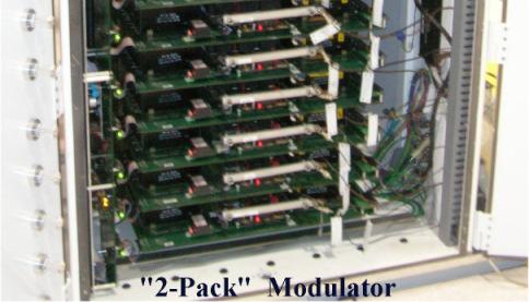
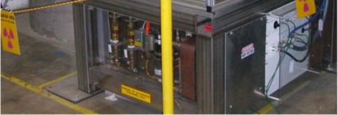
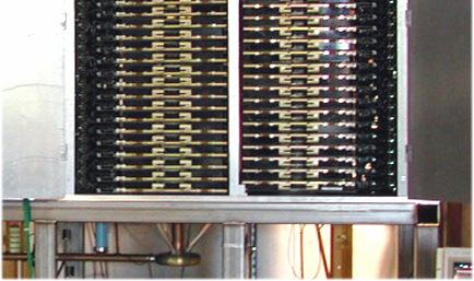
5 SLAC Induction Modulator Development 8/4-Pack Table-top 2-Pack Table-top kv capacitors 3.3 kv IGBT 6.5 kv IGBT Larger IGBT heat sink Page 5


 1800 volts per IGBT 2700 Amps per Driver")
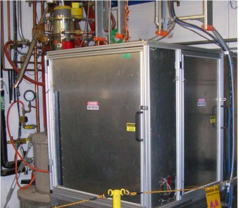
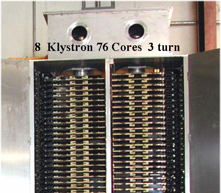
6 NLC 8-PACK (8-XP) MODULATOR Water Load 500 kv, 650 Amps CORES AND SECONDARY A 3 Turn Secondary A, 725 Meg watts for 3.2µs, 350 kw Ave. SOLID STATE DRIVERS 152 IGBT s Drivers (two per Primary) 1800 volts per IGBT 2700 Amps per Driver 5045 Klystron 400 kv, 450 Amps Page 6


 XL4 Klystrons")
7 NLC 4-PACK (4-XL4) MODULATOR controls Klystron supplies drivers CORES AND SECONDARY A 3 Turn Secondary A, XL4 Klystrons 320 A 1.6 µsec SOLID STATE DRIVERS 76 IGBT s Drivers 1800 volts per IGBT 3600 Amps per Driver (4) XL4 Klystrons 400kV 1200A Page 7


8 Table-top (6575 Equivalent) Modulator IGBT DRIVER Collector GRN Grid +15V Emitter DRVn1 C10 100ufd 3kv Dn1 8kv T10 Qn1 23 kv Cn A 1/1 50ufd 400v 2 ea 3.3Kv 800A IGBT drivers 10 CORE sections + + C31 100ufd 3kv 23 kv, 6.0 ka IGBT DRIVER Q31 D31 8kv T31 Collector V-Sec GRN C32 3 usec Grid +15V 1/1 Emitter 2 ea 3.3Kv 800A 50ufd 400v DRV31 C21 100ufd 3kv IGBT DRIVER Q21 D21 8kv T21 Collector GRN C22 Grid +15V 1/1 Emitter 2 ea 3.3Kv 800A 50ufd 400v DRV21 C11 100ufd 3kv IGBT DRIVER Q11 D11 8kv T11 Collector GRN C12 Grid +15V 1/1 Emitter 2 ea 3.3Kv 800A 50ufd 400v 5045 KLYSTRON 340 kv 396 A 3 us 1/15 Pulse Transformer A 20 IGBT drivers 2.2 kv, 2.7 ka 1 Turn Secondary 1:15 conventional X-former 330 kv, 360 A (Note: Rise time slow due to pulse transformer leakage inductance and stray capacitance) Page 8


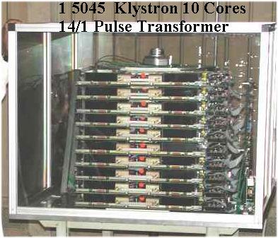
9 NLC DFM1 Hybrid Modulator Water Load 500kV 500A kv (2) XK4 capacitors Klystrons 400kV 440A DFM1 Hybrid modulator utilizing DFM fabricated parts; Larger IGBT heat sink15 Metglas cores, 30 IGBT drivers, with a single secondary turn driving a conventional 1:10 pulse transformer: 530kV, 600A, 1.6 µsec, 120 Hz Page 9


10 ORION 5045 Klystron Modulator 2 > 2 > 1 > 1 > 8 24kV, 6kA A 16 IGBT drivers: 3.0 kv, 3.1 ka 1 Turn Secondary 1:15 conventional X-former: 360 kv, 414 A 1) Iout 200A/V: 5 VOL µF kv 2) Vout 1kV/V: 5 VOL 500 nsec capacitors Resistive load 4 ohms 30nF Modulator only 24kV 6000A Page 10
11 SLAC Modulator Program Conclusions IGBT-based solid state modulators are capable of meeting (and exceeding) the high power klystron requirements R&D opportunities to improve efficiency, fault tolerance, and modulator lifetime Pulse power optimized IGBT High voltage, high bandwidth adder design Integrated HLRF design: optimize entire source including modulator Page 11
X-band Solid State Modulator Development. Craig Burkhart Power Conversion Department January 5, 2011
 X-band Solid State Modulator Development raig Burkhart Power onversion Department January 5, 20 Overview Inductive adder topology SLA development SLA team: Richard assel (SLA slide material) Minh Nguyen
Solid State Modulators for X-Band Accelerators
 Solid State Modulators for X-Band Accelerators John Kinross-Wright Diversified Technologies, Inc. Bedford, Massachusetts DTI X-Band Experience Developed and built two completely different NLC-class modulator
Chapter 4. Rf System Design. 4.1 Introduction Historical Perspective NLC Rf System Overview
 Chapter 4 Rf System Design 4.1 Introduction 4.1.1 Historical Perspective The design of the NLC main linacs is based on the extensive experience gained from the design, construction, and 35 years of operation
PULSED MODULATOR TECHNOLOGY
 PULSED MODULATOR TECHNOLOGY Hiroshi MATSUMOTO J-PARC/KEK CONTENTS 1. VARIOUS REQUIREMENT OF THE RECENT MODULATORS SHORT PULSE WIDTH (~µsec) LONG PULSE WIDTH (~msec) AND HIGH REP. RATE. (200 Hz) OUTPUT
Next Linear Collider. The 8-Pack Project. 8-Pack Project. Four 50 MW XL4 X-band klystrons installed on the 8-Pack
 The Four 50 MW XL4 X-band klystrons installed on the 8-Pack The Demonstrate an NLC power source Two Phases: 8-Pack Phase-1 (current): Multi-moded SLED II power compression Produce NLC baseline power: 475
J/NLC Progress on R1 and R2 Issues. Chris Adolphsen
 J/NLC Progress on R1 and R2 Issues Chris Adolphsen Charge to the International Linear Collider Technical Review Committee (ILC-TRC) To assess the present technical status of the four LC designs at hand,
KLYSTRON GUN ARCING AND MODULATOR PROTECTION
 SLAC-PUB-10435 KLYSTRON GUN ARCING AND MODULATOR PROTECTION S.L. Gold Stanford Linear Accelerator Center (SLAC), Menlo Park, CA USA Abstract The demand for 500 kv and 265 amperes peak to power an X-Band
INFN School on Electron Accelerators. RF Power Sources and Distribution
 INFN School on Electron Accelerators 12-14 September 2007, INFN Sezione di Pisa Lecture 7b RF Power Sources and Distribution Carlo Pagani University of Milano INFN Milano-LASA & GDE The ILC Double Tunnel
THE NEXT LINEAR COLLIDER TEST ACCELERATOR: STATUS AND RESULTS * Abstract
 SLAC PUB 7246 June 996 THE NEXT LINEAR COLLIDER TEST ACCELERATOR: STATUS AND RESULTS * Ronald D. Ruth, SLAC, Stanford, CA, USA Abstract At SLAC, we are pursuing the design of a Next Linear Collider (NLC)
A Unique Power Supply for the PEP II Klystron at SLAC*
 I : SLAC-PUB-7591 July 1997 A Unique Power Supply for the PEP II Klystron at SLAC* R. Case1 and M. N. Nguyen Stanford Linear Accelerator Center Stanford University, Stanford, CA 94309 Presented at the
L-Band RF R&D. SLAC DOE Review June 15 th, Chris Adolphsen SLAC
 L-Band RF R&D SLAC DOE Review June 15 th, 2005 Chris Adolphsen SLAC International Linear Collider (ILC) RF Unit (TESLA TDR Layout) Gradient = 23.4 MV/m Bunch Spacing = 337 ns Fill Time = 420 µs Train Length
X-Band Klystron Development at
 X-Band Klystron Development at SLAC Slide 1 The Beginning X-band klystron work began at SLAC in the mid to late 80 s to develop high frequency (4x SLAC s-band), high power RF sources for the linear collider
Overview of the X-band R&D Program
 Overview of the X-band R&D Program SLAC-PUB-9442 August 2002 Abstract T.O. Raubenheimer Stanford Linear Accelerator Center, Stanford University, Stanford, California 94309 USA An electron/positron linear
Towards an X-Band Power Source at CERN and a European Structure Test Facility
 Towards an X-Band Power Source at CERN and a European Structure Test Facility Erk Jensen and Gerry McMomagle CERN The X-Band Accelerating Structure Design and Test-Program Workshop Day 2: Structure Testing
RF considerations for SwissFEL
 RF considerations for H. Fitze in behalf of the PSI RF group Workshop on Compact X-Ray Free Electron Lasers 19.-21. July 2010, Shanghai Agenda Introduction RF-Gun Development C-band development Summary
CERN EUROPEAN ORGANIZATION FOR NUCLEAR RESEARCH. A 50 Hz LOW-POWER SOLID-STATE KLYSTRON-MODULATOR
 CERN EUROPEAN ORGANIZATION FOR NUCLEAR REEARCH CTF3 Note 051(Tech.) (IGCT witch) A 50 Hz LOW-POWER OLID-TATE KLYTRON-MODULATOR P. Pearce, L. ermeus, L. hen Abstract A solid-state klystron-modulator has
WG2 Group Summary. Chris Adolphsen Terry Garvey Hitoshi Hayano
 WG2 Group Summary Chris Adolphsen Terry Garvey Hitoshi Hayano Linac Options Fest On Thursday afternoon, various experts summarized the linac baseline options. Although hard choices have yet to be made,
NLC Review- Baseline Modulator
 NLC Review- Baseline Modulator Baseline- build today Develop Cost Model Approach _ Conventional A4odulator, Compromise of cost, reliability, efficiency and performance I modulator per 2 Klystrons ,NLC
45 MW, 22.8 GHz Second-Harmonic Multiplier for High-Gradient Tests*
 US High Gradient Research Collaboration Workshop. SLAC, May 23-25, 2007 45 MW, 22.8 GHz Second-Harmonic Multiplier for High-Gradient Tests* V.P. Yakovlev 1, S.Yu. Kazakov 1,2, and J.L. Hirshfield 1,3 1
Evaluation of Performance, Reliability, and Risk for High Peak Power RF Sources from S-band through X-band for Advanced Accelerator Applications
 Evaluation of Performance, Reliability, and Risk for High Peak Power RF Sources from S-band through X-band for Advanced Accelerator Applications Michael V. Fazio C. Adolphsen, A. Jensen, C. Pearson, D.
Pulsed Klystrons for Next Generation Neutron Sources Edward L. Eisen - CPI, Inc. Palo Alto, CA, USA
 Pulsed Klystrons for Next Generation Neutron Sources Edward L. Eisen - CPI, Inc. Palo Alto, CA, USA Abstract The U.S. Department of Energy (DOE) Office of Science has funded the construction of a new accelerator-based
PULSED POWER FOR FUTURE LINEAR ACCELERATORS
 PULSED POWER FOR FUTURE LINEAR ACCELERATORS Peter D. Pearce High-energy accelerators High-energy accelerators enable us to collide particle beams together and create conditions believed to be similar to
XFEL High Power RF System Recent Developments
 XFEL High Power RF System Recent Developments for the XFEL RF Group Outline XFEL RF System Requirements Overview Basic Layout RF System Main Components Multibeam Klystrons Modulator RF Waveguide Distribution
RF Power Generation II
 RF Power Generation II Klystrons, Magnetrons and Gyrotrons Professor R.G. Carter Engineering Department, Lancaster University, U.K. and The Cockcroft Institute of Accelerator Science and Technology Scope
Development of High Power Vacuum Tubes for Accelerators and Plasma Heating
 Development of High Power Vacuum Tubes for Accelerators and Plasma Heating Vishnu Srivastava Microwave Tubes Division, CSIR-Central Electronics Engineering Research Institute, Pilani-333031, Rajasthan,
NLC - The Next Linear Collider Project NLC R&D. D. L. Burke. DOE Annual Program Review SLAC April 9-11, 2003
 DOE Annual Program Review SLAC April 9-11, 2003 NLC Activities for the Past Year Accelerator Design centered around ILC-TRC studies. Technology R&D focused on the RF R&D. Modulator, klystron, SLED-II,
DEVELOPMENT OF X-BAND KLYSTRON TECHNOLOGY AT SLAC
 DEVELOPMENT OF X-BAND KLYSTRON TECHNOLOGY AT SLAC George Caryotakis, Stanford Linear Accelerator Center P.O. Box 4349 Stanford, CA 94309 Abstract * The SLAC design for a 1-TeV collider (NLC) requires klystrons
RF plans for ESS. Morten Jensen. ESLS-RF 2013 Berlin
 RF plans for ESS Morten Jensen ESLS-RF 2013 Berlin Overview The European Spallation Source (ESS) will house the most powerful proton linac ever built. The average beam power will be 5 MW which is five
CHAPTER 3 SEPARATION OF CONDUCTED EMI
 54 CHAPTER 3 SEPARATION OF CONDUCTED EMI The basic principle of noise separator is described in this chapter. The construction of the hardware and its actual performance are reported. This chapter proposes
Detailed Design Report
 Detailed Design Report Chapter 4 MAX IV Injector 4.6. Acceleration MAX IV Facility CHAPTER 4.6. ACCELERATION 1(10) 4.6. Acceleration 4.6. Acceleration...2 4.6.1. RF Units... 2 4.6.2. Accelerator Units...
OT 100/ /700 P5
 OT 100/120 277/700 P5 OPTOTRONIC Outdoor Constant current LED drivers Areas of application _ Street and urban lighting _ Industry _ Suitable for luminaires of protection class I Product benefits _ High
ILC RF System R&D. Chris Adolphsen, SLAC. Section of 1.3 GHz SC Linac. June 29, 2007 PAC07 Talk FRYC01
 ILC RF System R&D Chris Adolphsen, SLAC June 29, 2007 PAC07 Talk FRYC01 Section of 1.3 GHz SC Linac ILC Main Linac RF Unit (1 of 560) RF System Gradient = 31.5 MV/m Rep Rate = 5 Hz Beam Current = 9.0 ma
RF Solutions for Science.
 RF Solutions for Science www.thalesgroup.com State-of-the-art RF sources for your scientific needs High-power klystrons HIGH KLYSTRONS WITH RF LONG PULSE above 50 μs Thales has been one of the leading
Overview of NLC/JLC Collaboration *
 SLAC PUB 10117 August 2002 Overview of NLC/JLC Collaboration * K. Takata KEK, Oho, Tsukuba-shi 305-0801, JAPAN On behalf of the NLC Group Stanford Linear Accelerator Center, Stanford, California 94309,
High Power ARNS/IFF Limiter Module: Ultra Low Flat Leakage & Fast Recovery Time
 RELEASED RFLM-961122MC-299 High Power ARNS/IFF Limiter Module: Ultra Low Flat Leakage & Fast Recovery Time Features: SMT Limiter Module: 8mm x 5mm x 2.5mm Frequency Range: 960 MHz to 1,215 MHz High Average
Pulses inside the pulse mode of operation at RF Gun
 Pulses inside the pulse mode of operation at RF Gun V. Vogel, V. Ayvazyan, K. Floettmann, D. Lipka, P. Morozov, H. Schlarb, S. Schreiber FLASH Seminar, DESY March 29, 2011 Contents Why we need a PiPmode
A HIGH POWER LONG PULSE HIGH EFFICIENCY MULTI BEAM KLYSTRON
 A HIGH POWER LONG PULSE HIGH EFFICIENCY MULTI BEAM KLYSTRON A.Beunas and G. Faillon Thales Electron Devices, Vélizy, France S. Choroba DESY, Hamburg, Germany Abstract THALES ELECTRON DEVICES has developed
4.4 Injector Linear Accelerator
 4.4 Injector Linear Accelerator 100 MeV S-band linear accelerator based on the components already built for the S-Band Linear Collider Test Facility at DESY [1, 2] will be used as an injector for the CANDLE
High-power klystrons. The benchmark in scientific research. State-of-the-art RF sources for your accelerator
 > High- klystrons The benchmark in scientific research State-of-the-art RF sources for your accelerator Thales has been one of the leading manufacturers of RF and microwave sources for decades, and is
RF Upgrades & Experience At JLab. Rick Nelson
 RF Upgrades & Experience At JLab Rick Nelson Outline Background: CEBAF / Jefferson Lab History, upgrade requirements & decisions Progress & problems along the way Present status Future directions & concerns
X-Band klystron development at the Stanford Linear Accelerator Center
 SLAC-PUB-8346 March 2000 X-Band klystron development at the Stanford Linear Accelerator Center D. Sprehn, G. Caryotakis, E. Jongewaard, R. M. Phillips, and A. Vlieks Stanford Linear Accelerator Center
Design, Fabrication and Testing of Gun-Collector Test Module for 6 MW Peak, 24 kw Average Power, S-Band Klystron
 Available online www.ejaet.com European Journal of Advances in Engineering and Technology, 2014, 1(1): 11-15 Research Article ISSN: 2394-658X Design, Fabrication and Testing of Gun-Collector Test Module
2 Work Package and Work Unit descriptions. 2.8 WP8: RF Systems (R. Ruber, Uppsala)
") 2 Work Package and Work Unit descriptions 2.8 WP8: RF Systems (R. Ruber, Uppsala) The RF systems work package (WP) addresses the design and development of the RF power generation, control and distribution
2 Work Package and Work Unit descriptions 2.8 WP8: RF Systems (R. Ruber, Uppsala) The RF systems work package (WP) addresses the design and development of the RF power generation, control and distribution
DEVELOPMENT OF A 10 MW SHEET BEAM KLYSTRON FOR THE ILC*
 DEVELOPMENT OF A 10 MW SHEET BEAM KLYSTRON FOR THE ILC* D. Sprehn, E. Jongewaard, A. Haase, A. Jensen, D. Martin, SLAC National Accelerator Laboratory, Menlo Park, CA 94020, U.S.A. A. Burke, SAIC, San
Lecture 17 Microwave Tubes: Part I
 Basic Building Blocks of Microwave Engineering Prof. Amitabha Bhattacharya Department of Electronics and Communication Engineering Indian Institute of Technology, Kharagpur Lecture 17 Microwave Tubes:
ECGR 6264 RF Design Midterm Spring 2005
 ECGR 6264 RF Design Midterm Spring 2005 Name: Student Number: Do NOT begin until told to do so Make sure that you have all pages before starting Open notes DO ALL WORK ON THE SPACE GIVEN Do NOT use the
Wire Survival Test of Crowbar Less, High Voltage DC, Klystron Bias Power Supply
 Open Science Journal of Electrical and Electronic Engineering 2017; 4(1): 1-9 http://www.openscienceonline.com/journal/j3e Wire Survival Test of Crowbar Less, High Voltage DC, Klystron Bias Power Supply
A SHEET-BEAM KLYSTRON PAPER DESIGN
 SLAC-PUB-8967 A SHEET-BEAM KLYSTRON PAPER DESIGN G. Caryotakis Stanford Linear Accelerator Center, Stanford University, Stanford Ca. 94309 Abstract What may be the first detailed cold test and computer
Karin Rathsman, Håkan Danared and Rihua Zeng. Report from RF Power Source Workshop
 Accelerator Division ESS AD Technical Note ESS/AD/0020 Karin Rathsman, Håkan Danared and Rihua Zeng Report from RF Power Source Workshop 10 July 2011 Report on the RF Power Source Workshop K. Rathsman,
Development of klystrons with ultimately high - 90% RF power production efficiency
 Development of klystrons with ultimately high - 90% RF power production efficiency A. Baikov (MUFA), I. Syratchev (CERN), C. Lingwood, D. Constable (Lancaster University) Introduction FCC has high power
Modulator Overview System Design vs. Tunnel Topologies. Snowmass Workshop August 16, 2005 Ray Larsen for the SLAC ILC Group
 Modulator Overview System Design vs. Tunnel Topologies Snowmass Workshop August 16, 2005 Ray Larsen for the SLAC ILC Group Outline! I. Modulator Options vs. Topologies! II. Preliminary Cost Estimates!
Linac upgrade plan using a C-band system for SuperKEKB
 Linac upgrade plan using a C-band system for SuperKEKB S. Fukuda, M. Akemono, M. Ikeda, T. Oogoe, T. Ohsawa, Y. Ogawa, K. Kakihara, H. Katagiri, T. Kamitani, M. Sato, T. Shidara, A. Shirakawa, T. Sugimura,
SRS and ERLP developments. Andrew moss
 SRS and ERLP developments Andrew moss Contents SRS Status Latest news Major faults Status Energy Recovery Linac Prototype Latest news Status of the RF system Status of the cryogenic system SRS Status Machine
Electro-Optic Beam Deflectors
 Toll Free: 800 748 3349 Electro-Optic Beam Deflectors Conoptics series of electro-optic beam deflectors utilize a quadrapole electric field in an electro-optic material to produce a linear refractive index
Reprint of Poster Presentation EML, May Welleman, E. Ramezani, J. Walmeyer, S. Gekenidis
 Reprint of Poster Presentation EML, May 1998 Welleman, E. Ramezani, J. Walmeyer, S. Gekenidis ABB Semiconductors AG Fabrikstrasse 3, CH-5600 Lenzburg / Switzerland Tel.: +41-62-888-6381 Fax: +41-62-888-6310
DESIGN AND PERFORMANCE OF L-BAND AND S-BAND MULTI BEAM KLYSTRONS
 DESIGN AND PERFORMANCE OF L-BAND AND S-BAND MULTI BEAM KLYSTRONS Y. H. Chin, KEK, Tsukuba, Japan. Abstract Recently, there has been a rising international interest in multi-beam klystrons (MBK) in the
Improvements to the APS LINAC and SR/Booster klystron HVPS, and Accomplishments of the 352MHz RFTS
 Improvements to the APS LINAC and SR/Booster klystron HVPS, and Accomplishments of the 352MHz RFTS G. Trento Accelerator Systems Division Argonne National Laboratory Work supported by the U.S. Department
Jae-Young Choi On behalf of PLS-II Linac team
 PLS-II Linac 2015. 4. 8. Jae-Young Choi On behalf of PLS-II Linac team Accelerators in Pohang Accelerator Laboratory XFEL (under construction) 400 M$ Machines under installation PLS-II PAL : Chronology
IOT RF Power Sources for Pulsed and CW Linacs
 LINAC 2004 Lübeck, August 16 20, 2004 IOT RF Power Sources H. Bohlen, Y. Li, Bob Tornoe Communications & Power Industries Eimac Division, San Carlos, CA, USA Linac RF source property requirements (not
reported by T. Shintake KEK / RIKEN Japan Summary of C-band R&D for Linear Collider at KEK New soft-x-ray FEL Project at RIKEN/SPring-8
 C-band RF System R&D reported by T. Shintake KEK / RIKEN Japan Summary of C-band R&D for Linear Collider at KEK New soft-x-ray FEL Project at RIKEN/SPring-8 Project was funded in 2001 April Material Science
Klystron Tubes. Two forms of such a device, also called linear beam klystron, are given in the following figure.
 Klystron Tubes Go to the klystron index The principle of velocity-variation, first used in Heil oscillators, was also used in other microwave amplifying and oscillating tubes. The application for klystron
GA A26497 SOLID-STATE HIGH-VOLTAGE CROWBAR UTILIZING SERIES-CONNECTED THYRISTORS
 GA A26497 SOLID-STATE HIGH-VOLTAGE CROWBAR by J.F. Tooker, P. Huynh, and R.W. Street JUNE 2009 DISCLAIMER This report was prepared as an account of work sponsored by an agency of the United States Government.
HIGH VOLTAGE SWITCH PERFORMANCE OF THE EIMAC X-2159 TETRODE ABSTRACT
 HIGH VOLTAGE SWITCH PERFORMANCE OF THE EIMAC X-2159 TETRODE by Bobby R. Gray High Power Component & Effects Section Techniques Branch Surveillance Division Rome Air Development Center Griffiss Air Force
Current status of XFEL/SPring-8 project and SCSS test accelerator
 Current status of XFEL/SPring-8 project and SCSS test accelerator Takahiro Inagaki for XFEL project in SPring-8 inagaki@spring8.or.jp Outline (1) Introduction (2) Key technology for compactness (3) Key
Direct PWM. 1000/2000 Series POWERBLOK MODULE
 Direct PWM 1000/2000 Series POWERBLOK MODULE Features A universal servo-drive integrated on a Power Hybrid Module. Designed for direct PWM Servo Control Designed for use with Deta Tau's PMAC controllers
American Power Design, Inc.
 FEATURES 4 Customer Selects Output Voltage 4 Outputs to 8000 Vdc 4 Proportional Output Voltage 4 Six-Sided Shielded Case 4 60 khz Switching Frequency 4 5000 Vdc Output Isolation 4 Continuous Short Circuit
Test of ScannerMAX Saturn 1 with 600Hz Sine-wave input, having an optical scan angle of 40 optical degrees peak to peak.
 Test of ScannerMAX Saturn 1 with 600Hz Sine-wave input, having an optical scan angle of 40 optical degrees peak to peak. What follows are scope screen shots of a test of ScannerMAX Saturn 1B with our standard
IOT OPERATIONAL EXPERIENCE ON ALICE AND EMMA AT DARESBURY LABORATORY
 IOT OPERATIONAL EXPERIENCE ON ALICE AND EMMA AT DARESBURY LABORATORY A. Wheelhouse ASTeC, STFC Daresbury Laboratory ESLS XVIII Workshop, ELLETRA 25 th 26 th November 2010 Contents Brief Description ALICE
Development of Multiple Beam Guns for High Power RF Sources for Accelerators and Colliders
 SLAC-PUB-10704 Development of Multiple Beam Guns for High Power RF Sources for Accelerators and Colliders R. Lawrence Ives*, George Miram*, Anatoly Krasnykh @, Valentin Ivanov @, David Marsden*, Max Mizuhara*,
Spear3 RF System Sam Park 11/06/2003. Spear3 RF System. High Power Components Operation and Control. RF Requirement.
 Spear3 RF System RF Requirement Overall System High Power Components Operation and Control SPEAR 3 History 1996 Low emittance lattices explored 1996 SPEAR 3 proposed 11/97 SPEAR 3 design study team formed
FR205, 142 CPS1804. Power Supply Control .33Ω, 2W, K, nF. CPT uF 4148, 130 A64 3A-T , 116
 9 A B C D E F G H I J 17V for PS IC Remote Connector 100K, 113 392K, 529 0Ω, 132 30Ω,139 4937, 141 62K, 143A 002 POWER 510Ω, 004 1371 149 200pF, 138 0Ω, 533 FR205, 142 CPS1804 1 003 112 115A 18Ω, 133 Wire
Recent developments in cyclotrons for proton therapy at IBA
 Recent developments in cyclotrons for proton therapy at IBA Yves Jongen. Founder & CRO IBA sa We Protect, Enhance and Save Lives. A typical PT center 30-55 millions for equipment 45-100 millions for the
Ios english manual:ios english manual.qxd 07/08/ :35 Page 1
 Ios english manual:ios english manual.qxd 07/08/2008 10:35 Page 1 Ios english manual:ios english manual.qxd 07/08/2008 10:35 Page 2 Contents Introduction...1 Design Innovation...2-3 Installation...3 Ventilation...4
LED Driver Linear / area fixed output
 Driver LC 10W 350mA fixc lp SNC2 ESSENCE series Product description Fixed output built-in LED Driver Constant current LED Driver Output current 350 ma Max. output power 10.2 W Up to 80 % efficiency For
ILC-LNF TECHNICAL NOTE
 IL-LNF EHNIAL NOE Divisione Acceleratori Frascati, July 4, 2006 Note: IL-LNF-001 RF SYSEM FOR HE IL DAMPING RINGS R. Boni, INFN-LNF, Frascati, Italy G. avallari, ERN, Geneva, Switzerland Introduction For
CEPC Klystron Development
 CEPC Klystron Development Zusheng Zhou On behalf of High Efficiency RF Source R&D Collaboration Institute of High Energy Physics Sep. 26, 2018, HKUST, Hong Kong 1 Outline Strategy and plan 650MHz/800kW
Measurement, Protection and Controls
 5 th Modulator Klystron Workshop MDK2001 Session 2-1 Chairman : B. Frammery (CERN) Measurement, Protection and Controls Session 2-1 Measurement, Protection & Controls Session 2-1 - A new interlock system
SLAC X-band Technology R&D. Tor Raubenheimer DOE Briefing June 11 th, 2010
 SLAC X-band Technology R&D Tor Raubenheimer DOE Briefing June 11 th, 2010 Introduction Overall ARD strategy ILC Program X-band program Compact XFEL and other applications Status and development needs Proposed
clipping; yellow LED lights when limiting action occurs. Input Section Features
 ELX-1A Rack-Mount Mic/Line Mixer Four inputs, one output in a single rack space Very-highery-high-quality audio performance High reliability Extensive filtering circuitry and shielding protect against
LED Driver Compact fixed output
 Driver LC 40W 900mA fixc C SNC ESSENCE series Product description Fixed output built-in LED Driver Constant current LED Driver Output current 900 ma Max. output power 40 W Nominal life-time up to 50,000
Status of KEK X-band Test Facility and its future plans
 Status of KEK X-band Test Facility and its future plans Shuji Matsumoto Accelerator Lab., KEK 5/30/2007 US High Field Gradient Collaboration Workshop, SLAC. 1 Contents The New X-band Test Facility (XTF)
LED Driver Compact fixed output
 Driver LC 10W 250mA fixc R ADV ADV series Product description Fixed output built-in LED Driver Constant current LED Driver Output current 250 ma For luminaires of protection class II For ambient temperatures
16 Stage Bi-Directional LED Sequencer
 16 Stage Bi-Directional LED Sequencer The bi-directional sequencer uses a 4 bit binary up/down counter (CD4516) and two "1 of 8 line decoders" (74HC138 or 74HCT138) to generate the popular "Night Rider"
King Fahd University of Petroleum and Minerals Electrical Engineering Department 1. Homework 5 - SOLUTION KEY
 Electrical Engineering Department 1 Homework 5 - SOLUTION KEY EE-306 Electromechanical Devices - Semester 162 Electrical Engineering Department 2 Problem 1 Consider a Europeon city, it is necessary to
PHASED OUT. LED control gear Compact fixed output. Driver LC 40W 900mA fixc C SNC China Domestic ESSENCE series
 Product description Fixed output built-in LED Driver Constant current LED Driver Output current 900 ma Max. output power 40 W Nominal life-time up to 30,000 h For luminaires of protection class I and protection
HV823 & HV825 EL Lamp Driver Circuits. Lamp Color/Size (in 2 ) Lamp Brightness 1,2 (ft-lm)
 Lamp Brightness 1,2 (ft-lm)") HV & HV Driver Circuits ANH Note This application note presents fourteen driver circuits utilizing the Supertex HV and HV drivers. They have been optimized for a variety of applications and may be used
HV & HV Driver Circuits ANH Note This application note presents fourteen driver circuits utilizing the Supertex HV and HV drivers. They have been optimized for a variety of applications and may be used
FMS3810/3815 Triple Video D/A Converters 3 x 8 bit, 150 Ms/s
 Triple Video D/A Converters 3 x 8 bit, 150 Ms/s Features 8-bit resolution 150 megapixels per second 0.2% linearity error Sync and blank controls 1.0V p-p video into 37.5Ω or 75Ω load Internal bandgap voltage
LED Driver Compact fixed output
 Driver LC 45W 1050mA fixc C SNC ESSENCE series Product description Fixed output built-in LED Driver Constant current LED Driver Output current 1,050 ma output power 45 W Nominal life-time up to 50,000
Key Features and functions. General Description
 Technical Specification Summary Frequency Range 470 862MHz Typ. Gain 56 db P1dB 1400 W Typ. Efficiency >40 % @ 1dBcp Analogue TV 2400 Wps Temperature Range 0 to +45C DVB 290 Wrms Max VSWR 3:1 DTV 500 Wrms
USER MANUAL Goldmund PH3.8 Phono Preamplifier
 USER MANUAL Goldmund PH3.8 Phono Preamplifier Congratulations. Thank you for purchasing the Goldmund PH3.8 Phono Preamplifier. You have acquired the best Phono Preamplifier ever made for professional and
ADVANCED HIGH-POWER MICROWAVE VACUUM ELECTRON DEVICE DEVELOPMENT
 ADVANCED HIGH-POWER MICROWAVE VACUUM ELECTRON DEVICE DEVELOPMENT H. P. Bohlen, Inc., Palo Alto, CA Abstract The microwave 1 power requirements of particle accelerators have been growing almost exponentially
Introduction: CW SRF linac types, requirements and challenges High power RF system architecture
 RF systems for CW SRF linacs S. Belomestnykh Cornell University Laboratory for Elementary-Particle Physics LINAC08, Victoria, Canada October 1, 2008 Outline L band Introduction: CW SRF linac types, requirements
Status and Plans for PEP-II
 Status and Plans for PEP-II John Seeman SLAC Particle and Particle-Astrophysics DOE HEPAP P5 Review April 21, 2006 Topics Luminosity records for PEP-II in October 2005 Fall shut-down upgrades Run 5b turn
CP-830FP Chassis TX-29E50D TX-29E50D/B TX-29PS12D TX-29PS12F TX-29PS12P SPECIFICATIONS. Order No: PCZ C2
 Order No: PCZ0510103C2 SPECIFICATIONS Power Source: Power Consumption: 220-240V a.c.,50hz 100W Stand-by Power Consumption: 1,5W Aerial Impedance: 75Ω unbalanced, Coaxial Type Receiving System: PAL-I, B/G,
Synchronization circuit with synchronized vertical divider system for 60 Hz TDA2579C
 FEATURES Synchronization and horizontal part Horizontal sync separator and noise inverter Horizontal oscillator Horizontal output stage Horizontal phase detector (sync to oscillator) Triple current source
OTM-3550-SW FREQUENCY AGILE F.C.C. COMPATIBLE TELEVISION MODULATOR INSTRUCTION MANUAL
 FREQUENCY AGILE F.C.C. COMPATIBLE TELEVISION MODULATOR INSTRUCTION MANUAL Phone: (209) 586-1022 (800) 545-1022 Fax: (209) 586-1026 E-Mail: salessupport@olsontech.com 025-000233 REV E www.olsontech.com
LED control gear Compact fixed output. Uconverter LCI 55 W 1400 ma O010 TOP series Ø4,4. Ordering data
 Product description 1-channel for indoor use Inbuilt for luminaires of protection class I Output current and output voltage adjustable FA output 12 V TC input channel ominal life of 50,000 h (at ta max.
News from HZB / BESSY Wolfgang Anders at ESLS-RF Meeting September 2010 Trieste
 News from HZB / BESSY Wolfgang Anders at ESLS-RF Meeting September 2010 Trieste Outline Status Klystrons / IOT Modifications of transmitters New LINAC for BESSY II Status BERLinPro HoBiCaT Extension --
45 Hz to 500 Hz 1.0% Hz to 1 khz 2.0% + 3. Accuracy 0.09% + 2. Range / resolution. Range / resolution. Accuracy 1% + 2
 AC Voltage Range¹ / resolution 2 3 4 45 Hz to 500 Hz 1.0% + 3 500 Hz to 1 khz 2.0% + 3 600.0 mv / 0.1 mv 6.000 V / 0.001 V 60.00 V / 0.01 V 600.0 V / 0.1 V 1000 V / 1 V 1. All AC voltage ranges are specified
UNISONIC TECHNOLOGIES CO., LTD TL431L
 UNISONIC TECHNOLOGIES CO., LTD TL431L PROGRAMMABLE PRECISION REFERENCE DESCRIPTION The UTC TL431L is a three-terminal adjustable regulator with a guaranteed thermal stability over applicable temperature