Assembly Instructions And User Guide. Elite Nixie. Nixie Tube Clock Elite Issue 2 (07 June 2018)
|
|
|
- Meryl Caldwell
- 5 years ago
- Views:
Transcription


1 Assembly Instructions And User Guide Elite Nixie - 1 -
2 REVISION HISTORY Issue Number Date Reason for Issue 2 07 June 2018 Added more NL840 details 1 04 May 2018 New document - 2 -
3 1. INTRODUCTION Here are the key features of the ELITE Nixie: Hours, Minutes and Seconds display Direct drive to six medium size Nixie Tubes Supports IN-8, NL84x. Noiseless, Direct Drive giving optimum digit clarity Uses a Quartz Crystal Oscillator as the timebase 12 or 24 hour modes Programmable leading zero blanking Date display in either DD.MM.YY or MM.DD.YY or YY.MM.DD format Programmable date display each minute Scrolling display of date or standard display Alarm, with programmable snooze period Optional GPS / XTERNAsynchronisation with status indicator LED Dedicated DST button to switch between DST and standard time Supercapacitor backup. Keeps time during short power outages PIR Motion Sensor input and accessory available. Configurable timeout period Simple time setting using two buttons Configurable for leading zero blanking Double dot colon neon lamps 11 colon neon modes including AM / PM indication (top / bottom or left / right), railroad (slow or fast) etc. Seconds can be reset to zero to precisely the set time Programmable night mode - blanked or dimmed display to save tubes or prevent sleep disturbance Rear Indicator LEDs dim at night to prevent sleep disturbance Weekday aware Master Blank function to turn off HV/ tubes and LEDs on weekends or during working hours Separate modes for colon neons during night mode Standard, fading, or crossfading with scrollback display modes Slot Machine Cathode poisoning prevention routine Programmable RGB tube lighting select YOUR favourite colour palette 729 colours possible. Have a different colour or your choosing every hour, or autochanging colours Provision for adding switch for independently switching off RGB LEDs Not AC frequency dependent works in all countries All user preferences stored to non-volatile memory Additional wireless functions if XTERNA module used: - Display of outdoor temperature in Celsius or Fahrenheit. - Min / Max temperature in last 24 hours - Wireless, Auto Sync of time from GPS with auxilliary TCXO - GPS Sync time, and time since last GPS Fix - Voltage of XTERNA module battery - 3 -
4 1.4 SAFETY DANGER: The clock pcb includes a switched-mode voltage booster circuit. This generates nominally 170 Volts DC. Assembly may only be undertaken by individuals who are suitably qualified and experienced in electronics assembly, and are familiar with safe procedures for working with high voltages. If in doubt, refer to a suitably qualified engineer before proceeding. The voltages generated by this circuit can give a potentially LETHAL ELECTRIC SHOCK. DISCLAIMER: This product is supplied as a kit of parts, intended only for suitably qualified electronic engineers, who are suitably qualified and experienced in electronics assembly, and are familiar with safe procedures for working with high voltages. The supplier, his agents or associates accept no liability for any damage, injury or death arising from the use of this kit of parts. This is not a finished product, and the person assembling the kit is responsible for ensuring that the finished product complies with any applicable local regulations governing electrical equipment, eg. UL, CE, VDE
.")
5 2. TOOLS AND EQUIPMENT REQUIRED 2.1 Tools required to assemble the PCB. The following tools will be required to assemble the PCB: - Soldering iron with a small tip (1-2 mm). - Wire cutters to trim the excess component leads after soldering. (TIP: A small pair of nail clippers works very well for this function). - Wire strippers (TIP: A small pair of scissors is quite suitable). - Multimeter for voltage tests and for identifying the resistors. - A small hot air gun will be needed to shrink the heat shrink tubing over the neon lamp wires. 2.2 Materials you will need. Solder lead / tin solder is highly recommended. USE LEAD/ TIN SOLDER! Lead free solder, as now required to be used in commercial products in Europe, has a much higher melting point and can be very hard to work with. Desoldering wick (braid) can be useful if you accidentally create solder bridges between adjacent solder joints. 2.3 Other items you will need. The clock kit does not include a power adapter. The following type of adapter should be obtained and used with the kit: Output 12V DC regulated, minimum power output capability of 500mA Output plug: 2.1mm pin, centre positive. A suitable adapter is shown below: - 5 -
6 3. LIST OF COMPONENTS 3.1 Table of Components Driver Board Circuit Designation Part Description Resistors R1 4.7 KΩ, ¼ Watt R2 390 KΩ, ¼ Watt R3 4.7 KΩ, ¼ Watt R4, R5, R6 270 Ω, ¼ Watt R7 4.7 KΩ, ¼ Watt R8, R9, R Ω, ¼ Watt Capacitors C1, C2 220uF 16-25V Electrolytic C3 1uF, 250V Electrolytic C4 220uF 16-25V Electrolytic C5 10pF Ceramic C6 33pF Ceramic C7 0.22F Supercapacitor C8, C9 100nF Transistors Q1 IRFD220 Q2 MPSA42 Diodes D1, D2 1N5819 D3 1N4148 D4 1N5819 D5 UF4004 D6, D7, D8 3mm Yellow LED RGB1 RGB6 APA106 RGB LED Integrated Circuits IC1 LM2576 5V voltage regulator IC2 PIC16F1938 in socket Miscellaneous L1, L2 100uH inductor ALARM, SET, ADJ, DST Miniature push button IC2 Socket 28 Way narrow IC socket for IC2 PWR (12V IN Socket) 2.1mm PCB power socket GPS, PIR Surface mount 3.5mm jack socket LS1 Piezo sounder FUSE 500mA fuse X KHz watch crystal J1 12 way MicroMatch Connector (Female) CY18 Module Rx Module with 2 X 2 way connectors - 6 -
7 3.2 Packing Sheet Driver Board Part Description Quantity Resistors 270 Ω, ¼ Watt KΩ, ¼ Watt KΩ, ¼ Watt 1 Capacitors 10pF, Ceramic 1 33pF, Ceramic 1 100nF, Ceramic 2 220uF, 16-25V, Electrolytic 3 1uF, 250V, Electrolytic F 1 Transistors IRFD220 1 MPSA42 1 Diodes 1N N UF mm Yellow LED 3 APA106 RGB LED 6 Integrated Circuits LM2576 5V voltage regulator 1 PIC16F bit microcontroller 1 Miscellaneous 100uH inductor 2 Miniature push button 4 28 way narrow IC Socket for IC mm PCB power socket 1 Surface mount 3.5mm jack socket 2 Piezo sounder 1 500mA fuse 1 12 way MicroMatch connector 1 (Female) CY18 Rx Module 1 2 way Right angle connector KHz watch crystal Packing Sheet - Additional parts Driver Board Printed Circuit Board 159mm X 55mm 5cm black heat shrink tubing (5mm diameter) 20cm insulated wire for the whip antenna 2 X M3 X 5mm plastic screws 2 X M3 X 4mm plastic screws 2 X M3 X 6mm threaded hex spacer (plastic) Laser-cut Jig for forming and mounting the LEDs - 7 -
8 3.4 Packing Sheet - IN-8 Tube PCB Printed Circuit Board with pre-soldered HV5622 ICs 12 Way Micromatch connector (Male) 4 X 4mm neon lamps 30cm clear heat shrink 66 gold socket receptacles 2 X 100nF ceramic capacitors 6 X 15 KΩ, ¼ Watt resistors 4 X 390 KΩ, ¼ Watt resistors 2 X 50mm tall glass cover tubes 3.4 Packing Sheet - NL840 Tube PCB Printed Circuit Board with pre-soldered HV5622 ICs 12 Way Micromatch connector (Male) 4 X 4mm neon lamps 30cm clear heat shrink 66 gold socket receptacles 2 X 100nF ceramic capacitors 6 X 10 KΩ, ¼ Watt resistors 4 X 390 KΩ, ¼ Watt resistors 2 X 50mm tall glass cover tubes - 8 -
9 3.5 Parts Identification The resistors used in the kit are 1% tolerance metal film. They are marked with four coloured bands to identify the value. However it is sometimes unclear in which direction the bands should be read. Therefore, we recommend that the resistors be identified with a multimeter. Please note the fuse will look like one of the pictures below. It can easily be confused for a capacitor. It is a self-resetting fuse. Inductors L1 and L2 may take different apperances: - 9 -
) Clip off the polarization tab from the")


10 4. ASSEMBLY OF THE TUBE PCB 4.1 J2 (12 Way Micromatch connector (male)) Clip off the polarization tab from the connector as it is not needed. Then solder the connector into the tube PCB on the opposite side to the pre-soldered ICs. Now, proceed according to the tube type you are using. 4.2 IN-8 and NL84x Nixie Tubes There are 66 individual sockets that need to be soldered in. The best method is a follows. IN-8: Slide 11 sockets onto the 11 pins of the tube. NL84x: Slide 10 sockets onto the 10 outer pins on the tube. With reference to the PCB check which one of the inner pins is needed (the corresponding hole on the PCB is plated), and slide a socket over this pin too
11 Insert the tube with sockets into the PCB from the side with the pre-soldered ICs. Push firmly in. You may need to wiggle a little from side to side, to get all the sockets to fully go into the holes, to the level as shown below. Flip over the PCB and solder the pins, ensuring the tube stays vertical. Solder sparingly as soon as you see solder flow around the annulus, withdraw the solder and soldering iron. Remove the tube, Finally clip off the then solder the next tube locations long tails of the sockets. in turn


12 4.3 R20 R25 (15 KΩ or 10KΩ) R26 R29 (390 KΩ) C12, C13 (100nF) You can solder the top pads if its easier the holes are plated through, so it does not matter if you solder the top pads or the bottom pads. Don t solder top AND bottom, there is no need. As with all the components, after soldering clip the excess leads off. 4.4 AM1, AM2, PM1, PM2 (4 mm neon lamp) Each neon is separately addressable, and many flashing and indication modes are implemented see the configuration setup later in the manual. The AM1 and PM1 neons are taller, and mounted on the rear 2 locations. The leads of the two rear neons need to be extended. Use pieces of wire cut from leads of resistors to extend the wires so they are at least 40mm long: Next, cut the clear heat shrink tubing into 8 lengths: 4 lengths of 20mm and 4 lengths of 35mm: Slip the insulation over the neon lamp leads and with a hot air gun, shrink the tubing:


13 Finally, solder the neons in place on the PCB, with the taller neons at the back. The glass cover tubes can be placed over later. The IN-8 / NL84x tube PCB is now complete
) To solder this perfectly, it is best to")


14 5. ASSEMBLY OF THE DRIVER PCB 5.1 J1 (12 Way Micromatch connector (Female)) To solder this perfectly, it is best to fit the tube board temporarily so you can be sure everthing is in perfect alignment. Gather together the components below. The screws are the shorter, 4mm ones. Then screw the hex spacers in position as shown below and also loosely place the 12 way connector. Then place the tube PCB in position, and engage the 12 way connectors and screw together with the longer 5mm screws
 D3 (1N4148) C1, C2 (220uF) PWR (DC Socket) L1(100uH Inductor) IC1 (LM2576) IC1 is a Surface Mount part, but it is large and easy to solder.")

15 You can now solder the 12 way connector, on the bottom of the driver PCB. Then remove the tube PCB and all the screws and spacers. 5.2 Low Voltage Generator components. Fuse D1, D2 (1N5819) D3 (1N4148) C1, C2 (220uF) PWR (DC Socket) L1(100uH Inductor) IC1 (LM2576) IC1 is a Surface Mount part, but it is large and easy to solder. Start by wetting one pad with solder. Then place the part in position and heat the lead so the solder below it melts and anchors the part. The four other leads can then be soldered. Do not solder the heatsink tab. C1 and C2 are polarized. The Positive lead is the longest, and goes in the pad marked +. The diodes are also polarized the band on the part must match the band marked on the white PCB marking

16 5.3 Testing Low Voltage Power Supply. Identify the test GND, 5V and HV test points at the side of the PCB. Plug in the 12V DC power supply, and then test using a DC voltmeter: Touch the black probe on the GND test point and the red probe on the 5V test point. The voltage should measure between 5.6 and 5.9 Volts. If not, disconnect power and check your work. Do not proceed with the assembly until the error is corrected. Once the test is completed, disconnect the power. 5.4 High Voltage Generator components. Socket for IC2 R1, R3 (4.7 KΩ) R2 (390 KΩ) C3 (1uF) C4 (220uF) D4 (1N5819) D5 (UF4004) Q1 (IRFD220) L2 (100uH Inductor)


17 Take care that the notched end of the IC socket is at the end shown. However if after you solder the part you realise the notch is at the wrong end, DON T try to desolder it! Actually, so long as the IC has the correct orientation, the socket does not really matter. Also the MOSFET needs to be placed with the two joined pins as marked on the PCB. 5.5 High Voltage Generator Test. - Refer to the warnings on page 5 - Insert IC2 into its socket. Orient the notch on the IC with the notch on the IC socket and the PCB marking. - Power up the PCB, and using the GND and HV test points, measure the high voltage generated using a voltmeter on DC setting. It should be between 165 and 176 Volts. If this is in order, disconnect the power supply
 C5 (10pF) C6 (33pF) X1 (Watch Crystal) C8 (100nF) The")

18 5.6 R7 (4.7 KΩ) C5 (10pF) C6 (33pF) X1 (Watch Crystal) C8 (100nF) The 10pF capacitor is usually marked 10 and not surprisingly the 33pF is marked 33. The 100nF is marked 104. Don t switch C5 and C6 or the timekeeping will be very slow

19 5.7 Tube Test Now comes a very exciting part of the assembly the first tube test. Replace the two small hex spacers that support the tube PCB. Remember to use the smaller 4mm screws underneath the driver board. Plug in the tube PCB, taking care the fuse is not trapped under it, but stands to the side of the tube PCB. Take six Nixie Tubes corresponding to your tube PCB, and carefully insert into the sockets. Now power up. After a short delay, the tubes should light and all start counting from zero to 9 and repeat. Please note this is a count UP, not a count DOWN. If you contact us with a support issue at this stage, please be clear about the count UP. If you refer to a count DOWN, it will be very confusing and slow down your support query! If you do not get this count UP, or have missing or overlapping digits, stop and check your work. Missing digits is usually rectified by pinching the tube contacts (when powered off!) so they make better contact with the tube. Also try swapping tubes around to see if the problem is with the tube, or the location. Please make these basic tests before contacting us for help and have the results to hand. Once completed, remove the tube PCB and store it safely
 C7 (0.")


20 5.8 R4, R5, R6, R8, R9, R10 (270Ω) Q2 (MPSA42) 5.9 LS1(Piezo sounder) C7 (0.22F) C9 (100nF) PIR, GPS (SMD Jack Sockets) The 0.22F capacitor is polarised note the arrows on the PCB, to correspond with the arrows on the part. To solder the SMD jack sockets, first tin one pad per jack socket: Then place the socket over the pad and re-heat the pad to wet the solder and anchor the part. The remaining pads can then be soldered


21 5.10 CY18 Module and Connectors Push the two connectors onto the end pins of the CY18 receiver Module. Then position on the PCB. Press the black connectors level with the the PCB,and check alignment of the module before soldering the four pads. Then withdraw the CY18 module until later


22 5.11 SET, ADJ, DST, ALARM (Push button switch) Only solder the two pins closest to the board edge. The other two pins are the frame and are not electrically connected. By only soldering the two active pads, if you make a mistake it is much easier to remove or re-position the switches! It is easier to solder one pin per switch first, then re-position by rewetting the pad until the switch is fully pushed into position. Then solder the second pin D6, D8 (3mm Yellow LED) Using the LED bending jig, bend D6 and D8 as shown below


23 Now the anode leads of the LEDs will be in the correct orientation as you insert into the holes in the PCB behind the ALARM and DST switches. Use the jig again, to align the LEDs above the switches. This will give the correct spacing for if you want to use one of our cases. Now bend and solder D7. The longer lead goes in the pad with a circle around it. Think about the orientation before you bend the leads. D7 should be level with the GPS jack socket next to it, and protrude by its full body length from the rear of the PCB
 Using the large hole")


24 5.13 RGB1 RGB6 (APA106 RGB LED) Using the large hole in the LED jig, bend the LED leads in three steps as shown below, noting the position of the longer two leads. Then install the RGB LEDs from the base of the PCB


25 To prevent excess stray light, you can add small pieces of the 5mm heat shrink over the LEDs. It is not necessary to shrink the tubing. If you choose to shrink it, be careful as it may shrink so narrow that almost no light comes out Antenna wire Strip 3mm insulation from the end of the wire supplied and cut the wire to 17cm length. Solder the wire to the ANT pad as shown below

26 5.15 Final Assembly Plug in the wireless receiver module. Then re-attach the tube board. You can now place the glass colon covers over the neons
27 6. HOW TO OPERATE THE CLOCK The four buttons have the following functions: SET: Exit tube test routine on cold power-up; Show date; Set time and date; Enter configuration menu; ADJ: Adjust: time, date, alarm time, configuration parameters; Enter XTERNA Stats Menu; ALARM: Set alarm time; snooze; cancel snooze/alarm; DST: Toggle between DST and Standard Time (+/- 1 Hour) Enter colour setup menu; scroll through colour / time options Entering configuration mode: The principal settings of the clock are stored in flash memory your preferred configuration is stored even after powering off the clock for extended periods. To access the configuration mode press and hold the SET button. After 2 seconds the seconds will become highlighted. Continue holding the button a further 2 seconds until the clock displays in this format: 00-XX-99. The 99 in the seconds digits tells you that you are in the configuration menu. In configuration mode the hours digits diplay the current parameter being adjusted, and the minutes digits display the current value stored against the parameter. For each parameter, and referring to the table below, scroll through the range of possible values by pressing the ADJ button. When the desired value has been reached, move on to the next parameter by pressing the SET button. When the last parameter has been set, pressing SET one more time will revert the clock back to time display mode. The first parameter (0) cannot be changed as it is the software revision number. It will show for several seconds and then move to parameter 1. In all correspondence on support issues, please quote the board type, revision date and software version
28 Parameter Description Values 0 Software revision 20 = version 2.0, 12 = version 2.1 etc 1 12 / 24 Hr mode 0 12 Hr (default) 1 24 Hr 2 Date format 0 = MM.DD.YY (default) 1 = DD.MM.YY 2 = YY.MM.DD 3 Leading zero blanking eg. 01:54:32 0 leading zero blanked (default) 1 leading zero displayed 4 Night Mode start hour Night Mode end hour Night Mode 0 Tubes off 1 Dimmed display (default) 7 Master Blank start hour Master Blank end hour Master Blank days 1 0 Off (default) 1 Weekdays 2 - Weekends 3 All days 10 Colon neons mode 0 Both off 1 AM/PM Indication, left / right 2 AM/PM Indication, left / right flashing 3 AM/PM Indication, top / bottom 4 AM/PM Indication, top / bottom flashing 5 All slow flashing 6 Slow flashing left / right 7 All flashing 8 Both illuminated 9 Railroad fast 10 Railroad slow 11 Colon neons during night dimmed mode 2 As per parameter Radio time signal source 3 0 to 3 reserved 4 GPS 5 - XTERNA 13 GPS Baud rate Kbps Kbps (default) 14 Radio time offset hours 0-13 (default 0) 4 15 Radio time offset mins 0-45 (default 0) 4 16 Radio time offset polarity 0 - Minus time (default) 1 Plus time 17 PIR Motion Sensor Period 0 No PIR installed (default) 1 15 seconds 2 30 seconds 3 1 minute 4 2 minutes 5 5 minutes 6 10 minutes 7 15 minutes 8 20 minutes 9 30 minutes
29 18 Snooze period 0 6 minutes (default) 1 9 minutes 2 12 minutes 3 15 minutes 19 Reserved 20 Time Calibration Factor 0-99 (each unit adjusts by 0.2s per day) 21 Time Calibration Polarity 0 - Make clock slower 1 - Make clock faster 22 Slots Mode 5 0 Slots disabled 1 Slots every minute 2 - Slots every 10 minutes (default) 3 - Slots every hour 4 Slots at midnight 23 Reserved 24 Reserved 25 Reserved 26 Display Mode 0 standard change of digits 1 fading digits 2 fading digits with scrollback effect (default) 27 Auto date display each minute 0 Off 1 - Static display of date 2 Scrolling display of date (default) (default 0 gives 15 seconds override) 9 28 Night Mode Override minutes 29 Thermometer Settings 0 Don t display temperature 1 Fahrenheit display (default) 2 Celsius display 30 Reserved 31 Restore default settings 0 Keep user settings 1 Restore original default settings 8 Notes: 1. Master Blanking Mode has priority over Night Mode. Use to disable the clock on weekends (eg clock is in office), or during office hours (eg clock is at home). Complete HV shutdown to save power and tube life. 2. Night time neons mode is active when night mode is set to dim. During night time blanking the tubes AND neons are disabled. 3. Clock is fully functional without GPS / XTERNA synchronisation. Set time manually. 4. Enter your time zone offset from the synchronisation source. Note that GPS transmits UTC. 5. Visual effect / cathode poisoning prevention all digits on all tubes are cycled for 10 seconds. 6. Date will be displayed each minute between 50 and 55 seconds past the minute. 7. Press SET briefly during Night Mode to show time for prescribed period. 8. Set this parameter to 1 to restore factory configuration settings. Internal operations will then load all the original settings and restore the value to
30 Setting the Time and Date: Before setting the time, press 'DST' briefly to toggle between DST and standard time modes. Set according to whether you are currently in DST time or not. The adjacent DST LED will light or extinguish accordingly. From time display mode, press and hold SET button for 2 seconds until the seconds digits are highlighted. Press the ADJ button to reset seconds to zero. Briefly Press SET again and the hours will be highlighted Press the ADJ button to set the minutes. Briefly Press SET again and the hours will be highlighted. Press the ADJ button to set the hours. Proceed in this fashion to set the calendar: Year, Month and Day. Finally, briefly Press SET again to revert to normal clock operation. Showing Date: From time display mode, briefly press SET button. Date will be shown for 5 seconds, then revert to time display. Auto Date Display: Setting parameter 27 to 1 or 2 will enable auto display of date between 50 and 55 seconds past each minute. Night Blanking Override: During programmed night blanking, the blanking may be overridden to see the time by briefly pressing the SET button. Tubes will remain lit for the period defined in parameter 28. Setting Alarm: Press the ALARM Button. The seconds digits show the on / off status of the alarm: 00 (off) or 01 (on). Set on / off status, then minutes followed by hours by using the ALARM and ADJ buttons. When set, the alarm LED will also light
31 Cancelling Alarm: Press ALARM briefly to cancel alarm and enter snooze mode, or a longer press until the clock bleeps, to cancel snooze. Alarm remains set for subsequent days. Rapid DST Adjustment Press DST briefly to toggle between DST and standard time. The indicator shows whether DST mode is active or not. Note, that GPS time data does not contain DST information, so the DST status will need to be set manually in GPS sync mode as well as manual time-set mode. Calibration of Timekeeping Accuracy Over time you may observe the clock runs faster or slower than an accurate time standard. You can finely adjust the timekeeping by setting configuration parameters 20 and 21. We recommend to precisely set the clock against a known accurate clock, and then record the time drift in seconds after 5 full days (120 hours). Program this value into parameter 20. Set parameter 21 to 0 to slow down the clock and to 1 to speed up the clock
32 7. XTERNA FUNCTIONS 7.1 About the XTERNA Module XTERNA is our new concept for synchronising time and capturing outdoor temperature for display on our clock and thermometer kits. Driven by a PIC microcontroller with advanced low power modes, the XTERNA captures time from GPS satellites every 6 hours, and stores in an on-board Temperature Controlled Crystal Oscillator (TCXO). Further, the device captures outdoor temperature every 10 minutes from an on-board DS18B20 digital temperature sensor. Every 10 minutes XTERNA transmits the time and temperature data, which can be received by our XTERNA compatible clocks. Additional data is transmitted such as battery voltage and GPS fix time. Supplied as a complete hobby kit of parts (For shipping reasons, batteries are not included), the kit takes approx minutes to comfortably assemble. The TCXO IC is pre-soldered, so there is no fiddly SMD soldering to worry about. Naturally, XTERNA is sealed against rain ingress. Battery life is estimated between 6 to 12 months. We recommend high quality branded batteries for the longest operation between battery changes. The module should be placed outdoors. But as close as possible to the indoor clock or thermometer and away from direct sunlight. 7.2 Specification Working Temperature Range: -40 C to +60 C. (-40 F to +140 F) Typical Reception Range: 10 to 30 Metres (30 to 100 ft). 7.3 Configuring for XTERNA Reception Elite Class Nixie Clocks are configured by default for XTERNA reception. If you have changed your configuration settings, you need to set parameter 12 to value 5. Also parameters 14, 15, 16 need to be set to specify your location s offset from UTC
 with the DST button. 7.5 Temperature Display The temperature is also transmitted with the time.")
33 7.4 Time Synchronisation Function XTERNA broadcasts every 10 minutes. After configuring your clock, please be patient in waiting for the first Synchronisation. Upon synchronisation the yellow LED D7 will illuminate. Remember to set DST ( Summer Time ) with the DST button. 7.5 Temperature Display The temperature is also transmitted with the time. Therefore, temperature will not be displayed until after the first synchronisation. Set Celsius or Fahrenheit using parameter 29: Fahrenheit: 1 Celsius : 2 Temperature is displayed between 30 and 35 seconds past each minute. Celsius is displayed with 0.5 C resolution. Fahrenheit is displayed with 1 F resolution. Positive and negative temperature is indicated by the left hand neons: Neon indicator PM2 acts as a decimal point. 7.6 Temperature Validity If no valid data is received on the next scheduled sync (every 10 minutes), the temperature will be deemed to be old and invalid. Temperature will not be shown until a new valid temperature is received


34 7.7 XTERNA Stats menu The Stats menu is accessible only if relevant XTERNA data has been received. From time display, press ADJ to enter the Stats Menu. Six items of data are displayed in sequence, stepped through by pressing the ADJ button sequentially, and finally exiting back to time display. Please see the table below. Stats Menu Item Description 1 Minimum Temperature in last 24 hours Range of Values -40 C to +60 C 40 F to 140 F Example 2 Maximum Temperature in last 24 hours -40 C to +60 C 40 F to 140 F 3 Voltage of XTERNA Battery 2.5V to 5.0V 4 Time required for last GPS fix loaded into the TCXO 0 to 98 sec 99 = no fix at last attempt 5 Hours and minutes since last GPS fix loaded into the TCXO 00:00 to 99:99 6 XTERNA Firmware version 1.00 onwards

35 8. CONFIGURING THE RGB LED TUBE LIGHTS The clock features a separate and dedicated setup menu for the RGB LED lights, accessed from the DST button. All settings are stored to non-volatile memory, so your favourite colours will still be there after even after a long power off. You can set fixed colours and intensities, or program an auto colour cycling effect at your choice of speed. 8.1 Entering RGB LED menu Press and hold the DST button until the display shows: 00: 0:00. NX3 will not be lit. For each hour (0-23), you can set a custom colour Each custom colour can have your choice of BLUE, GREEN and RED values from 0 (colour off) to 8 (maximum brightness) Mix the colours using the ALARM, ADJ, SET buttons. Use low values (1,2 and 3) for low brightness, eg. For night time Set the value to 0 for that colour to be off Once you are happy with the colour for that hour, press DST to move to the next hour Have fun playing with your favourite colours and intensities!


36 Colours are displayed live during RGB menu: In the example above, between 11 and 12 hours, the LEDs will be purple (8 blue, 0 green, 8 red) In the example below, between 19 and 20 hours, the LEDs will be blue with a hint of green (8 blue, 2 green and 0 red)

37 8.2 Setting auto colour cycling Setting colour RED to value 9 has a special meaning: This will enable auto colour cycling for the specified hour. The speed of the cycling will then be governed by the GREEN value: 0 = very slow change 9 = very fast change This auto colour cycling mode is explained in the picture below: Red = 9, therefore Auto Colour Cycling is enabled for hours Green = 3, so speed is 3. Blue value has no effect. Note: The colours do not cycle live during Auto Colour Cycling setup. The cycling starts only during normal time and date display

38 9. USING A GPS RECEIVER The clock can receive time from a GPS receiver that transmits information using NMEA-0183 protocol, using the $GPRMC sentence. 9.1 Configuring for GPS Synchronisation. Set parameter 12 to value 4. Set the baud rate in parameter 13. Set parameters 14 and 15 for the hours and minutes your time zone is offset from UTC Time. This is usually only whole hours. Set parameter (16) to identify whether the offset is minus (0) or positive (1) of the time source. D7 will light when the clock has received a recent GPS or XTERNA synchronisation data


39 10. PIR MOTION SENSOR The clock has a 3.5mm Jack Plug socket for connection of our PIR Motion Sensor Accessory, available separately as a quick build kit. This useful accessory helps save tube life and power by powering down the clock when it senses the room is empty. The sensing range is typically up to 12 ft (3.5 metres) When installed and configured (configuration parameter 17), the sensor will sense motion in the room, and switch off the High Voltage generator, tubes and RGB LEDs when the PIR time period has expired. Configuration Parameter 17: 0 No PIR installed (default) 1 15 seconds 2 30 seconds 3 1 minute 4 2 minutes 5 5 minutes 6 10 minutes 7 15 minutes 8 20 minutes 9 30 minutes It is important to remember that the function does not override Night Blanking and Master Blanking, so when the clock is in Night Blanking or Master Blanking, no amount of jumping around in front of the sensor will light the tubes! If you are using the PIR motion sensor, the Night Blanking and Master Blanking periods are rather redundant, so it is recommended to not use these if you have the PIR installed. The suggested initial PIR period is 10 minutes (Config 17 = 6)

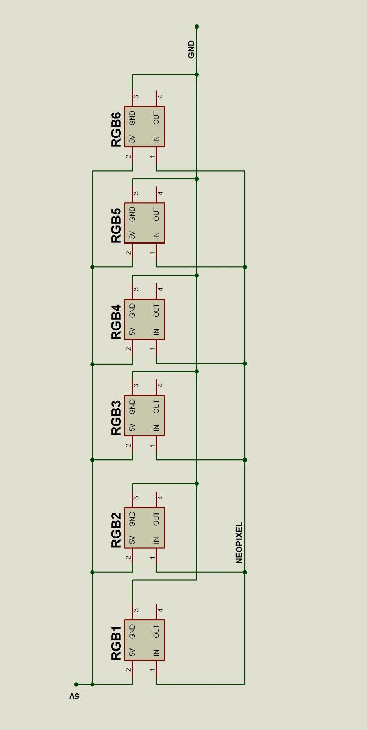
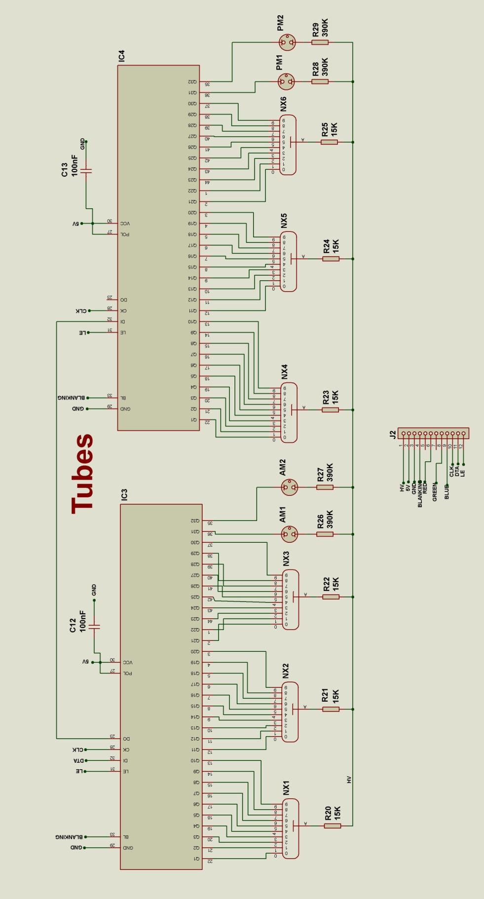
40 11. CIRCUIT DIAGRAM
41 - 41 -
42 - 42 -
Nixie Clock Type Quattro'
 Assembly Instructions And User Guide Nixie Clock Type Quattro' - 1 - Issue Number Date REVISION HISTORY 2 8 Sept 2012 Errors corrected 1 27 July 2012 New document Reason for Issue - 2 - 1.1 Nixie Quattro
Assembly Instructions And User Guide. Nixie FunKlock. FunKlock Issue 4 (1 February 2017)
") Assembly Instructions And User Guide Nixie FunKlock - 1 - Issue Number Date REVISION HISTORY 4 1 February 2017 New diode for D2 3 27 December 2013 C7 / C8 error page 15 2 7 November 2013 Errors corrected
Assembly Instructions And User Guide Nixie FunKlock - 1 - Issue Number Date REVISION HISTORY 4 1 February 2017 New diode for D2 3 27 December 2013 C7 / C8 error page 15 2 7 November 2013 Errors corrected
Nixie Clock Type Nixie Maestro
 Assembly Instructions and User Guide Nixie Clock Type Nixie Maestro - 1 - Issue Number Date REVISION HISTORY Reason for Issue 4 01 April 2017 New version with neons for AM / PM 3 10 December 2014 Typing
SN-Class Nixie Clock Kits
 Assembly Instructions And User Guide SN-Class Nixie Clock Kits - 1 - REVISION HISTORY Issue Date Reason for Issue Number 1 20 November 2017 New document - 2 - 1. INTRODUCTION 1.1 About the How can the
Nixie Clock Type IN-8 & NL840 Nixie'
 Assembly Instructions And User Guide Nixie Clock Type IN-8 & NL840 Nixie' - 1 - REVISION HISTORY Issue Number Date 4 15 December 2016 New diode for D2 3 30 August 2014 Typos 2 25 June 2014 Added NL840
Nixie Clock Type Frank 3'
 Assembly Instructions And User Guide Nixie Clock Type Frank 3' - 1 - REVISION HISTORY Issue Number Date Reason for Issue 4 16 December 2016 New diode for D2 3 12 November 2012 Improved first clock test
Nixie Clock Type Nixie QTC Plus
 Assembly Instructions And User Guide Nixie Clock Type Nixie QTC Plus - 1 - REVISION HISTORY Issue Date Number Draft 1 29 August 2018 New document Reason for Issue - 2 - 1. INTRODUCTION 1.1 Nixie QTC Plus
Nixie Clock Type SixNix
 Assembly Instructions And User Guide Nixie Clock Type SixNix - 1 - Issue Number Date REVISION HISTORY Reason for Issue 6 20 March 2014 Removed WWVB Support 5 14 July 2012 New Board Issue - 19 July 12 4
Nixie Clock Type Frank 2 Z570M
 Assembly Instructions And User Guide Nixie Clock Type Frank 2 Z570M Software version: 7R PCB Revision: 11 April 09-1 - 1. INTRODUCTION 1.1 About the clock Nixie clock type Frank 2 is a compact design with
Nixie Clock Type Nixie QTC
 Assembly Instructions And User Guide Nixie Clock Type Nixie QTC - 1 - REVISION HISTORY Issue Number Date Reason for Issue 12 10 September 2015 C6 changed to 33pF 11a 11 December 2014 C5 changed to 10pF.
Nixie Clock Type Frank 3
 Assembly Instructions And User Guide Nixie Clock Type Frank 3 Software version: 7R PCB Version: 11 April 09-1 - 1. INTRODUCTION 1.1 About the clock Nixie clock type Frank 3 is a compact design with all
Nixie Tube Clock Type Marsden
 Assembly Instructions And User Guide Nixie Tube Clock Type Marsden Software version: RTC-1.3 PCB Revision: 16 Aug 10-1 - 1. INTRODUCTION 1.1 About the clock Nixie clock type Marsden is a compact design
Documentation VFD clock 8 a clock
 Documentation VFD clock 8 a clock This documentation is protected by our copyright. It must not be used for commercial purposes. Congratulations on your purchase of your VFD clock. To guarantee success
Nixie Clock Kit V1.08 Assembly and Operation
 Nixie Clock Kit V1.08 Assembly and Operation Hardware Revision 14.05.2005 Software Version 6.0 Revision 19.04.2006 This document is copyrighted. No parts of this documentation may be used commercially.
Arduino Nixie Clock Modular Rev3
 Arduino Nixie Clock Modular Rev3 Operating Instructions Firmware V348 Supported Models: Modular Revision 3 NixieClockUserManualV348 About this document This is the user instruction manual for the Nixie
Introduction 1. Green status LED, controlled by output signal ST. Sounder, controlled by output signal Q6. Push switch on input D6
 Introduction 1 Welcome to the GENIE microcontroller system! The activity kit allows you to experiment with a wide variety of inputs and outputs... so why not try reading sensors, controlling lights or
Arduino Nixie Clock Classic Rev4 and Rev5 All In One Modular Rev2
 Arduino Nixie Clock Classic Rev4 and Rev5 All In One Modular Rev2 Operating Instructions Firmware V47 Supported Models: Classic Rev4 Classic Rev5 Modular Rev2 All-In-One NixieClockUserManualV47 About this
Arduino Nixie Clock Modular Rev3
 Arduino Nixie Clock Modular Rev3 Operating Instructions Firmware V352 Supported Models: Modular Revision 3 NixieClockUserManualV352 About this document This is the user instruction manual for the Nixie
DIY KIT MHZ 8-DIGIT FREQUENCY METER
 This kit is a stand-alone frequency meter capable of measuring repetitive signals up to a frequency of 50MHz. It has two frequency ranges (15 and 50 MHz) as well as two sampling rates (0.1 and 1 second).
Arduino Nixie Clock Classic Rev4 and Rev5 All In One
 Arduino Nixie Clock Classic Rev4 and Rev5 All In One Operating Instructions Firmware V52 Supported Models: Classic Rev4 Classic Rev5 All-In-One NixieClockUserManualV52 About this document This is the user
DDS VFO CONSTRUCTION MANUAL. DDS VFO Construction Manual Issue 1.1 Page 1
 DDS VFO CONSTRUCTION MANUAL DDS VFO Construction Manual Issue 1.1 Page 1 Important Please read before starting assembly STATIC PRECAUTION The DDS VFO kit contains the following components which can be
Nixie Clock Kit IN-12B color LED backlit Operation Manual Nixie Clock Kit IN-12B V6.0 ( All Right Reserved 2015 )
") Nixie Clock Kit IN-B color LED backlit Operation Manual Nixie Clock Kit IN-B V. ( All Right Reserved ) - - Operation Manual IN-B Nixie Clock Power for your Nixie Clock The clock does not include a wall
Nixie Clock Kit IN-B color LED backlit Operation Manual Nixie Clock Kit IN-B V. ( All Right Reserved ) - - Operation Manual IN-B Nixie Clock Power for your Nixie Clock The clock does not include a wall
7 SEGMENT LED DISPLAY KIT
 ESSENTIAL INFORMATION BUILD INSTRUCTIONS CHECKING YOUR PCB & FAULT-FINDING MECHANICAL DETAILS HOW THE KIT WORKS CREATE YOUR OWN SCORE BOARD WITH THIS 7 SEGMENT LED DISPLAY KIT Version 2.0 Which pages of
COLOUR CHANGING USB LAMP KIT
 TEACHING RESOURCES SCHEMES OF WORK DEVELOPING A SPECIFICATION COMPONENT FACTSHEETS HOW TO SOLDER GUIDE SEE AMAZING LIGHTING EFFECTS WITH THIS COLOUR CHANGING USB LAMP KIT Version 2.1 Index of Sheets TEACHING
Tube Cricket Build Guide
 Tube Cricket Build Guide The Tube Cricket is a small-wattage amp that puts out about 1 watt of audio power. With a 12AU7 tube-preamp and a JRC386 power amp, the Tube Cricket gives you great tone in a compact
Christmas LED Snowflake Project
 Christmas LED Snowflake Project Version 1.1 (01/12/2008) The snowflake is a follow-on from my Christmas star project from a few years ago. This year I decided to make a display using only white LEDs, shaped
ELECTRONIC GAME KIT TEACHING RESOURCES. Version 2.0 BUILD YOUR OWN MEMORY & REACTIONS
 TEACHING RESOURCES SCHEMES OF WORK DEVELOPING A SPECIFICATION COMPONENT FACTSHEETS HOW TO SOLDER GUIDE BUILD YOUR OWN MEMORY & REACTIONS ELECTRONIC GAME KIT Version 2.0 Index of Sheets TEACHING RESOURCES
MAKE AN RGB CONTROL KNOB.
 MAKE AN RGB CONTROL KNOB. This is a knob based colour changing controller that uses a custom programmed microcontroller to pack a lot of features into a small affordable kit. The module can drive up to
MONO AMPLIFIER KIT ESSENTIAL INFORMATION. Version 2.2 CREATE YOUR OWN SPEAKER DOCK WITH THIS
 ESSENTIAL INFORMATION BUILD INSTRUCTIONS CHECKING YOUR PCB & FAULT-FINDING MECHANICAL DETAILS HOW THE KIT WORKS CREATE YOUR OWN SPEAKER DOCK WITH THIS MONO AMPLIFIER KIT Version 2.2 Build Instructions
N3ZI Digital Dial Manual For kit with Backlit LCD Rev 4.00 Jan 2013 PCB
 N3ZI Digital Dial Manual For kit with Backlit LCD Rev 4.00 Jan 2013 PCB Kit Components Item Qty Designator Part Color/Marking PCB 1 LCD Display 1 LCD 1602 Volt Regulator 1 U1 78L05, Black TO-92 Prescaler
Bill of Materials: Super Simple Water Level Control PART NO
 Super Simple Water Level Control PART NO. 2169109 Design a simple water controller in which electrodes are required to sense high and low water levels in a tank. Whenever the water level falls below the
VU-1 VU Meter Kit Volume Unit Meter
 VU-1 VU Meter Kit Volume Unit Meter Simplicity Counts, Detail Matters. No part of this document may be reproduced, either mechanically or electronically, posted online on the Internet, in whole or in part,
Introduction 1. Digital inputs D6 and D7. Battery connects here (red wire to +V, black wire to 0V )
") Introduction 1 Welcome to the magical world of GENIE! The project board is ideal when you want to add intelligence to other design or electronics projects. Simply wire up your inputs and outputs and away
Introduction 1 Welcome to the magical world of GENIE! The project board is ideal when you want to add intelligence to other design or electronics projects. Simply wire up your inputs and outputs and away
Mal-2 assembly guide v1.0
 Mal-2 assembly guide v.0 SONIC POTIONS Schematic and BOM The BOM can be found on Google Docs Prepare the PCB Separate the PCBs using some pliers. PCB We start with the lower PCB and assemble it beginning
Timer Modules. MEU11 24 Hour Module, MEU17 7 Day Module (Without Housing)
") Timer Modules MEU11 24 Hour Module, MEU17 7 Day Module (Without Housing) EMU11 24 Hour Module, EMU17 7 Day Module (With Housing Giving panel mounting facility) Installation & Operating Instructions 1 1.
Timer Modules MEU11 24 Hour Module, MEU17 7 Day Module (Without Housing) EMU11 24 Hour Module, EMU17 7 Day Module (With Housing Giving panel mounting facility) Installation & Operating Instructions 1 1.
QUIZ BUZZER KIT TEACHING RESOURCES. Version 2.0 WHO ANSWERED FIRST? FIND OUT WITH THIS
 TEACHING RESOURCES SCHEMES OF WORK DEVELOPING A SPECIFICATION COMPONENT FACTSHEETS HOW TO SOLDER GUIDE WHO ANSWERED FIRST? FIND OUT WITH THIS QUIZ BUZZER KIT Version 2.0 Index of Sheets TEACHING RESOURCES
NewScope-7A Operating Manual
 2016 SIMMCONN Labs, LLC All rights reserved NewScope-7A Operating Manual Preliminary May 13, 2017 NewScope-7A Operating Manual 1 Introduction... 3 1.1 Kit compatibility... 3 2 Initial Inspection... 3 3
Aspect 2 Circuit Digital Scene Control
 Aspect 2 Circuit Digital Scene Control S p e c i f i c a t i o n 2 circuits of trailing edge dimming 500W total between the two circuits Both circuits feature independent overload, short-circuit and open-circuit
Introduction 1. Green status LED, controlled by output signal ST
 Introduction 1 Welcome to the magical world of GENIE! The project board is ideal when you want to add intelligence to other design or electronics projects. Simply wire up your inputs and outputs and away
N3ZI Digital Dial Manual For kit with Serial LCD Rev 3.04 Aug 2012
 N3ZI Digital Dial Manual For kit with Serial LCD Rev 3.04 Aug 2012 Kit properly assembled and configured for Standard Serial LCD (LCD Not yet connected) Kit Components Item Qty Designator Part Color/Marking
Arduino IN-14 Nixie Clock v42 All-In-One Clock Operating Instructions & Construction Manual
 Arduino IN-14 Nixie Clock v42 All-In-One Clock Operating Instructions & Construction Manual NixieClockIN14InstructionManualRev2V42 Contact Information If you want to get in contact with us, please email
LCD Thermometer / Clock S No. 1253
 Installation and Operating Manual LCD Thermometer / Clock S No. 1253 The 3 fold thermometer with crystal clock is purpose build for the mounting in caravans, boats and intervention vehicles. Please read
American DJ. Show Designer. Software Revision 2.08
 American DJ Show Designer Software Revision 2.08 American DJ 4295 Charter Street Los Angeles, CA 90058 USA E-mail: support@ameriandj.com Web: www.americandj.com OVERVIEW Show Designer is a new lighting
Arduino Modular IN-14 Nixie Clock Rev2 V45 All-In-One Modular Clock Operating Instructions & Construction Manual
 Arduino Modular IN-14 Nixie Clock Rev2 V45 All-In-One Modular Clock Operating Instructions & Construction Manual NixieClockModularInstructionManualRev2V45 Contact Information If you want to get in contact
DIY Guide - Building Franky v1.1, the SEGA Audio and Videocard for MSX
 DIY Guide - Building Franky v1.1, the SEGA Audio and Videocard for MSX 2015 FRS & MSXpró. Translation by FRS and Supersoniqs. Table of Contents Introduction... 3 Materials needed... 3 Audio volume boost...
Multi-Key v2.4 Multi-Function Amplifier Keying Interface
 Multi-Key v2.4 Multi-Function Amplifier Keying Interface ASSEMBLY & OPERATION INSTRUCTIONS INTRODUCTION The Harbach Electronics, LLC Multi-Key is a multi-function external device designed for the safe
8 PIN PIC PROGRAMMABLE BOARD (DEVELOPMENT BOARD & PROJECT BOARD)
") ESSENTIAL INFORMATION BUILD INSTRUCTIONS CHECKING YOUR PCB & FAULT-FINDING MECHANICAL DETAILS HOW THE KIT WORKS LEARN ABOUT PROGRAMMING WITH THIS 8 PIN PIC PROGRAMMABLE BOARD (DEVELOPMENT BOARD & PROJECT
ESSENTIAL INFORMATION BUILD INSTRUCTIONS CHECKING YOUR PCB & FAULT-FINDING MECHANICAL DETAILS HOW THE KIT WORKS LEARN ABOUT PROGRAMMING WITH THIS 8 PIN PIC PROGRAMMABLE BOARD (DEVELOPMENT BOARD & PROJECT
Total solder points: 123 Difficulty level: beginner 1. advanced AUDIO ANALYZER K8098. audio gea Give your. . high-tech ILLUSTRATED ASSEMBLY MANUAL
 Total solder points: 123 Difficulty level: beginner 1 2 3 4 5 advanced AUDIO ANALYZER K8098 ra audio gea Give your. look high-tech ILLUSTRATED ASSEMBLY MANUAL H8098IP-1 Features & Specifications Features
SceneStyle2 User Guide
 SceneStyle2 User Guide Mode Lighting (UK) Limited. The Maltings, 63 High Street, Ware, Hertfordshire, SG12 9AD, UNITED KINGDOM. Telephone: +44 (0) 1920 462121 Facsimile: +44 (0) 1920 466881 e-mail: website:
WiFi Time Provider v1 for Arduino Nixie Clock Operating Instructions & Construction Manual
 WiFi Time Provider v1 for Arduino Nixie Clock Operating Instructions & Construction Manual Document V001c Contact Information If you want to get in contact with us, please email to: nixie@protonmail.ch
Timer Modules. EL11 24 Hour Module EL17 7 Day Module. Installation & Operating Instructions
 Timer Modules EL11 24 Hour Module EL17 7 Day Module Installation & Operating Instructions 1 1. General Information These instructions should be read carefully and retained for further reference and maintenance.
GUIDE TO ASSEMBLY OF ERICA SYNTHS DELAY MODULE
 If you are reading this, most probably, you are about to build Erica Synths DIY DELAY module. The module is 4mm deep, skiff friendly, has solid mechanical construction and doesn t require wiring. Erica
Instrukcja montażu. FLEX LED Neon Instalacja
 FLEX LED Neon Instalacja Instrukcja montażu Polned Sp. z o.o. ul. Falencka 7 PL05-090 Janki Tel. +48 22 4903434 +48 22 4903243 www.polned.pl info@polned.pl. Product Checking: 1) Unpack and carefully examine
TKEY-K16. Touch CW automatic electronic keyer. (No moving parts no contacts) Assembly manual. Last review: March 15, 2018
 Assembly manual. Last review: March 15, 2018") TKEY-K16 Touch CW automatic electronic keyer (No moving parts no contacts) Assembly manual Last review: March 15, 2018 Commands and use manual of the K16 and Updates and news: www.ea3gcy.com Thanks for
TKEY-K16 Touch CW automatic electronic keyer (No moving parts no contacts) Assembly manual Last review: March 15, 2018 Commands and use manual of the K16 and Updates and news: www.ea3gcy.com Thanks for
DTS400B - DZS400BP 3/9/07 10:14 AM Page 1
 DTS400B - DZS400BP 3/9/07 10:14 AM Page 1 18 DTS400B - DZS400BP 3/9/07 10:14 AM Page 3 TABLE OF CONTENTS Section Page Capabilities and Features.......... 1 Installation Instructions............ 2 Instructions
STX Stairs lighting controller.
 Stairs lighting controller STX-1795 The STX-1795 controller serves for a dynamic control of the lighting of stairs. The lighting is switched on for consecutive steps, upwards or downwards, depending on
Thank you for purchasing this product. If installing for someone else, please ensure that the instructions are handed to the householder.
 Instruction Manual TPSE201 (181422) - BOSS TM Universal Programmer TPSE101 (569565) - BOSS TM Universal Timeswitch Thank you for purchasing this product. If installing for someone else, please ensure that
Digital Clock. Perry Andrews. A Project By. Based on the PIC16F84A Micro controller. Revision C
 Digital Clock A Project By Perry Andrews Based on the PIC16F84A Micro controller. Revision C 23 rd January 2011 Contents Contents... 2 Introduction... 2 Design and Development... 3 Construction... 7 Conclusion...
FSM User Guide Page 1 of 28
 FSM User Guide Page 1 of 28 Field Strength Meter User Guide and Kit Assembly Instructions PCB V1.1 Important: Always use or print this document in colour as there are references to the colours of components.
This document is intended to provide information to allow the researcher to build their own device.
 SEXTA Construction Notes Tony Barry, Dave Gault Preamble:- SEXTA is a system (hardware device, firmware, and application software) to create and analyse optical timestamps as observed by a camera and recorder.
Safety Information. Camera System. If you back up while looking only at the monitor, you may cause damage or injury. Always back up slowly.
 Table of Contents Introduction...3 Safety Information...4-6 Before Beginning Installation...7 Installation Guide...8 Wiring Camera & Monitor...9-10 Replacement Installation Diagram...11 Clip-On Installation
XTAL Bank DDS Version 0.02 Sept Preliminary, highly likely to contain numerous errors
 XTAL Bank DDS Version 002 Sept 7 2012 Preliminary, highly likely to contain numerous errors The photo above shows the fully assembled Xtal Bank DDS with 2 DDS modules installed (The kit is normally only
Total solder points: 117 Difficulty level: beginner advanced. RGB Controller K8088 ILLUSTRATED ASSEMBLY MANUAL
 Total solder points: 117 Difficulty level: beginner 1 2 3 4 5 advanced RGB Controller K8088 Control incandescent bulbs, LEDs, common anode led strips, etc... ILLUSTRATED ASSEMBLY MANUAL H8088IP-1 Features
RECORD & PLAYBACK KIT
 TEACHING RESOURCES SCHEMES OF WORK DEVELOPING A SPECIFICATION COMPONENT FACTSHEETS HOW TO SOLDER GUIDE ADD AN AUDIO MESSAGE TO YOUR PRODUCT WITH THIS RECORD & PLAYBACK KIT Version 2.1 Index of Sheets TEACHING
NETWORK COMPASS USER MANUAL CONTENTS
 CONTENTS NETWORK COMPASS USER MANUAL GENERAL INTRODUCTION TO B&G NETWORK...2 INTRODUCTION TO NETWORK COMPASS...3 COMPASS DISPLAY UNIT...4 EXAMPLE SYSTEMS USING NETWORK COMPASS...4 INITIAL POWER-UP...5
Lab 7: Soldering - Traffic Light Controller ReadMeFirst
 Lab 7: Soldering - Traffic Light Controller ReadMeFirst Lab Summary The two-way traffic light controller provides you with a quick project to learn basic soldering skills. Grading for the project has been
ULTRA-VANSTAT WIRELESS PROGRAMMABLE THERMOSTAT FOR CARAVANS
 ULTRA-VANSTAT WIRELESS PROGRAMMABLE THERMOSTAT FOR CARAVANS NOT SUPPLIED PROGRAMMER / TRANSMITTER RECEIVER THIS DOMESTIC STYLE WIRELESS 7 DAY PROGRAMMABLE HEATER CONTROL REPLACES THE TRUMA ULTRAHEAT SWITCH
OWNER S MANUAL MOTORIZED 7 WIDE TFT LCD COLOR MONITOR CNT-701
 OWNER S MANUAL PW MOTORIZED 7 WIDE TFT LCD COLOR MONITOR CNT-701 ANY CHANGES OR MODIFICATIONS IN CONSTRUCTION OF THIS UNIT DEVICE WHICH IS NOT APPROVED BY THE PARTY RESPONSIBLE FOR COMPLIACE COULD VOID
Modellbahn Digital Peter Stärz
 Modellbahn Digital Peter Stärz Dresdener Str. 68 D-02977 Hoyerswerda +49 3571 404027 www.firma-staerz.de info@firma-staerz.de 8-fold Track Occupancy Detector for digital systems with two-wire track (e.g.
7 Day Digital Programmer 3 Channel Surface Mount
 7 Day Digital Programmer 3 Channel Surface Mount Model: TRT038N Installation & Operating Instructions 1. General Information These instructions should be read carefully and retained for further reference
16 Stage Bi-Directional LED Sequencer
 16 Stage Bi-Directional LED Sequencer The bi-directional sequencer uses a 4 bit binary up/down counter (CD4516) and two "1 of 8 line decoders" (74HC138 or 74HCT138) to generate the popular "Night Rider"
Fixed Audio Output for the K2 Don Wilhelm (W3FPR) & Tom Hammond (NØSS) v August 2009
 & Tom Hammond (NØSS) v August 2009") Fixed Audio Output for the K2 Don Wilhelm (W3FPR) & Tom Hammond (NØSS) v. 2.1 06 August 2009 I have had several requests to provide a fixed audio output from the K2. After looking at the circuits that
Fixed Audio Output for the K2 Don Wilhelm (W3FPR) & Tom Hammond (NØSS) v. 2.1 06 August 2009 I have had several requests to provide a fixed audio output from the K2. After looking at the circuits that
Ten-Tec (865) Service Department:(865)
 Service Department:(865)") Ten-Tec (865) 453-7172 Service Department:(865) 428-0364 Installation Instructions for Ten-Tec Jupiter AT538K Tuner Kit The installation of the AT538K is divided into two steps. The first step is to reprogram
Ten-Tec (865) 453-7172 Service Department:(865) 428-0364 Installation Instructions for Ten-Tec Jupiter AT538K Tuner Kit The installation of the AT538K is divided into two steps. The first step is to reprogram
VU Meter Buffer DIY Kit
 VU Meter Buffer DIY Kit Warning This document is distributed for educational purposes only. This equipment operates at potentially lethal voltages. Only trained, qualified personnel should operate, maintain,
Azatrax Model Railroad Track Signal Control - Single Track
 Installation Guide Azatrax Model Railroad Track Signal Control - Single Track TS2 What it is: The TS2 operates one or two trackside block signals (one in each direction) on one track to simulate the block
Revision 1.2d
 Specifications subject to change without notice 0 of 16 Universal Encoder Checker Universal Encoder Checker...1 Description...2 Components...2 Encoder Checker and Adapter Connections...2 Warning: High
INSTALLATION & USER GUIDE
 INSTALLATION & USER GUIDE Digidim 458 8-Channel Dimmer STEP 1 Assemble Dimmer Unit STEP 2 Mount Dimmer Chassis STEP 3 Electrical Installation STEP 4 Attach Module and Make Connections STEP 5 Replace Cover
FRQM-2 Frequency Counter & RF Multimeter
 FRQM-2 Frequency Counter & RF Multimeter Usage Instructions Firmware v2.09 Copyright 2007-2011 by ASPiSYS Ltd. Distributed by: ASPiSYS Ltd. P.O.Box 14386, Athens 11510 (http://www.aspisys.com) Tel. (+30)
LP20. Installation & User Guide. Dual Channel Programmer. Part number 25039DR
 Dual Channel Programmer Part number 25039DR! For GREENSTAR CDi, GREENSTAR i JUNIOR and GREENSTAR Si MODELS also GREENSTAR i SYSTEM and GREENSTAR CDi SYSTEM MODEL(only when used with the optional integral
SINGLE ZONE CLIMATE ZONING SYSTEM. Technical Manual. Polyaire Pty Ltd
 SINGLE ZONE CLIMATE ZONING SYSTEM Technical Manual Polyaire Pty Ltd 11-13 White Road GEPPS CROSS South Australia, 5094 Tel: (08) 8349 8466 Fax: (08) 8349 8446 www.polyaire.com.au CONTENTS Features 1 Application
Industrial Monitor Update Kit
 Industrial Monitor Update Kit (Bulletin Number 6157) Installation Instructions 2 Table of Contents Table of Contents Industrial Monitor Update Kit... 3 Overview... 3 Part 1 - Initial Preparation... 5 Part
Vorne Industries. 87/719 Analog Input Module User's Manual Industrial Drive Itasca, IL (630) Telefax (630)
 Telefax (630)") Vorne Industries 87/719 Analog Input Module User's Manual 1445 Industrial Drive Itasca, IL 60143-1849 (630) 875-3600 Telefax (630) 875-3609 . 3 Chapter 1 Introduction... 1.1 Accessing Wiring Connections
Vorne Industries 87/719 Analog Input Module User's Manual 1445 Industrial Drive Itasca, IL 60143-1849 (630) 875-3600 Telefax (630) 875-3609 . 3 Chapter 1 Introduction... 1.1 Accessing Wiring Connections
Model DT-311J. And DT-311J-230V(AC) DIGITAL STROBOSCOPE INSTRUCTION MANUAL
 DIGITAL STROBOSCOPE INSTRUCTION MANUAL") Test Equipment Depot - 800.517.8431-99 Washington Street Melrose, MA 02176 - TestEquipmentDepot.com Model DT-311J And DT-311J-230V(AC) DIGITAL STROBOSCOPE INSTRUCTION MANUAL 1. GENERAL The DT-311J DIGITAL
Test Equipment Depot - 800.517.8431-99 Washington Street Melrose, MA 02176 - TestEquipmentDepot.com Model DT-311J And DT-311J-230V(AC) DIGITAL STROBOSCOPE INSTRUCTION MANUAL 1. GENERAL The DT-311J DIGITAL
The NorCal SMT Dummy Load Assembly and Operating Manual Rev. 1.0 January 4, 2005
 The NorCal SMT Dummy Load Assembly and Operating Manual Rev. 1.0 January 4, 2005 Copyright 2005 W3CD 1 1. Introduction The NorCal SMT Dummy Load is a practice kit for anyone wishing to gain some experience
Building the BX24-AHT
 Building the BX24-AHT file:///f /LASER/build-it.htm (1 of 8) [03/04/2002 5:21:52 PM] file:///f /LASER/build-it.htm (2 of 8) [03/04/2002 5:21:52 PM] Tips & Tricks Use a 25W or smaller soldering iron with
Inputs and outputs. Connecting leads. Buzzer
 Inputs and outputs Mr Bit experiments are designed to help younger pupils get started with connecting sensors and devices to the BBC micro:bit. They are useful 'warm-up' activities before attempting Mr
Lab 7: Soldering - Traffic Light Controller ReadMeFirst
 Lab 7: Soldering - Traffic Light Controller ReadMeFirst Lab Summary The two way traffic light controller provides you with a quick project to learn basic soldering skills. Grading for the project has been
ADD AN AUDIO MESSAGE TO YOUR PRODUCT WITH THIS RECORD & PLAYBACK KIT
 ADD AN AUDIO MESSAGE TO YOUR PRODUCT WITH THIS RECORD & PLAYBACK KIT BUILD INSTRUCTIONS Before you start take a look at the Printed Circuit Board (PCB). The components go in the side with the writing on
FD Trinitron Colour Television
 R 4-205-569-32(1) FD Trinitron Television Instruction Manual GB KV-14LM1U 2000 by Sony Corporation NOTICE FOR CUSTOMERS IN THE UNITED KINGDOM A moulded plug complying with BS1363 is fitted to this equipment
JS007WQK HEAVY DUTY WIRELESS REVERSING KIT 7 LCD DIGITAL QUAD RECORDING MONITOR with WATERPROOF CCD CAMERA
 JS007WQK HEAVY DUTY WIRELESS REVERSING KIT 7 LCD DIGITAL QUAD RECORDING MONITOR with WATERPROOF CCD CAMERA The JS007WQK is loaded with userfriendly features and is ideal for use in heavy duty vehicles.
LINK-RAY TM MODULATORS FOR CONSTANT- VOLTAGE. LinkRay Modulators 12 V / 24 V Constant-voltage Applications MODULATORS
 MUSIUM RESTAURANT SOUVENIR SHOP EXIT LinkRay Modulators 12 V / 24 V Constant-voltage Applications LINK-RAY TM MODULATORS FOR CONSTANT- VOLTAGE LINK-RAY TM MODULATORS FOR CONSTANT-VOLTAGE APPLICATIONS 186755
AXE101 PICAXE-08M2 Cyberpet Kit
 AXE101 PICAXE-08M2 Cyberpet Kit The Cyberpet project uses a PICAXE-08M2 microcontroller with two LEDs as the pets eyes and a piezo sounder as a voice for the pet. The project also uses a switch so that
RD RACK MOUNT DIMMER OWNERS MANUAL VERSION /09/2011
 RD - 122 RACK MOUNT DIMMER OWNERS MANUAL VERSION 1.3 03/09/2011 Page 2 of 14 TABLE OF CONTENTS UNIT DESCRIPTION AND FUNCTIONS 3 POWER REQUIREMENTS 3 INSTALLATION 3 PLACEMENT 3 POWER CONNECTIONS 3 OUTPUT
EPROM pattern generator with "Genlock"
 EPROM pattern generator with "Genlock" This generator uses an EPROM to store several pictures that can then be selected by means of a thumb-wheel switch. Alternatively, if the pictures stored are in a
Installing The PK-AM keyer and. from Jackson Harbor Press Operating: A Morse code keyer chip with pot speed control
 Installing The PK-AM keyer and from Jackson Harbor Press Operating: A Morse code keyer chip with pot speed control The PK-AM keyer is a modification for the PK-AM kit, it changes the AM transmitter to
L, LTC, LTM, LT are registered trademarks of Linear Technology Corporation. Other product
 DESCRIPTION WARNING! Do not look directly at operating LED. This circuit produces light that can damage eyes. Demo Circuit 1265 QUICK START GUIDE LTC3220/LTC3220-1 360mA Universal 18-Channel LED Driver
Installation and User Guide 458/CTR8 8-Channel Ballast Controller Module
 Installation and User Guide 458/CTR8 8-Channel Ballast Controller Module Helvar Data is subject to change without notice. www.helvar.com i Contents Section Page Introduction 1 Installation 2 1. Attach
Peak Atlas IT. RJ45 Network Cable Analyser Model UTP05. Designed and manufactured with pride in the UK. User Guide
 GB05-7 Peak Atlas IT RJ45 Network Cable Analyser Model UTP05 Designed and manufactured with pride in the UK User Guide Peak Electronic Design Limited 2001/2013 In the interests of development, information
XTM72E & F Real-Time Clock Modules
 Capricorn Controls Ltd Data & Application Notes Page 1 of 8 XTM72E & F Real-Time Clock Modules Originally designed to compliment our wide range of Gen-Set controls, these DC powered Real-Time-Clocks have
Bill of Materials: Magic Color PART NO
 Magic Color PART NO. 2193838 Magic color is a guessing game. With this game you can surprise your friends and leave them with amazement, how the game guesses what they have in their minds. Only two selections