Overview of NIRS Accelerator Activity
|
|
|
- Charleen Ward
- 5 years ago
- Views:
Transcription


1 Overview of NIRS Accelerator Activity Koji Noda Research Center for Charged Particle Therapy National Institute of Radiological Sciences Workshop on Hadron Beam Therapy April , Erice, Italy Hospital
2 1. Introduction Contents 2. Tour 3. Development of Technologies at 4. Compact Carbon-Therapy Facility 5. New Treatment-Facility Project


3 Heavy Ion Medical Accelerator in Chiba 1. Introduction Tokyo Narita international airport National Institute of Radiological Sciences Chiba Prefecture
 charged particles He, C, Ne, Si, Ar Range: 30cm in soft tissue 800MeV/u (Si) Maximum irradiation area: 22cmΦ Dose rate: 5Gy/min Beam")
4 facility 1. Introduction Ion species: High LET (100keV/μm) charged particles He, C, Ne, Si, Ar Range: 30cm in soft tissue 800MeV/u (Si) Maximum irradiation area: 22cmΦ Dose rate: 5Gy/min Beam direction: horizontal, vertical Size: 7200 m 2 (60 x 120 m) Cost: 320 M US$ (32,600 M JPY) 135 M$ for building 165 M$ for machine (Heavy Ion Medical Accelerator in Chiba)
5 Progress of treatment number 1. Introduction advanced medicine. clinical study Treatment Period: 43 wks 1st Term(Apr Aug): 18.5wks 2nd Term(Sept Feb):24.5wks Treatment: 4 days per week Total: 4504 (Jun 1994 Feb 2009)

6 Statistics of treatment 1. Introduction Eye Lachrymal Digestive duct Lung Liver Rectum Brain Head & Neck Bone & Soft tissue Pancreas Prostate Uterus Tumors Miscellaneous Prostate Lung Eye Head and Rectum Neck Bone/Soft Tissue Uterus Liver Prostate Rectum Bone & Soft Uterus tissue Pancreas CNS Pancreas Liver Uveal Melanoma Lung Skull Base Digestive duct Esophagus Lymph Lachrymal Nodes Lacrimal Gland Brain Head Others & Neck Patients Total No.: 4, The histogram shows the number of tumors treated from June 94 to Feb. 09. Total number is 4,502, and treatments of more than 30% are utilized with irradiation gated with respiration.
7 Typical operation 1. Introduction Mon Tue Wed Thu Hour Maintenance or tuning Beam R&D Treatment Treatments: Daytime on weekday Experiment (Phys.&Bio): Night and daytime on weekend. Machine maintenance: Daytime on Monday. Fri Sat Sun Experiment Shutdown Operation time: 8300h/2ring Breakdown ratio:0.6%@ 04


")
8 1. Introduction Result of clinical trials Lung Treatment planning GyE T2N0M0 stage IB 28GyE (1 fraction) before 1 year after
9 1. Introduction Contents 2. Tour 3. Development of Technologies at 4. Compact Carbon-Therapy Facility 5. New Treatment-Facility Project

10 Linac cascade Ion source tour 2. Tour Synchrotron Irradiation system Treatment room Transport line


11 Ion source 2. Tour 10GHz-ECR source PIG source 18GHz-ECR source


12 Linac cascade 2. Tour Alvarez Linac RFQ Linac There are a cascade of linear accelerators consists of RFQ-linac and Alvarez linac. Both are operated with 100MHz RF power. RFQ first accelerates up to 800keV/n, then the Alvarez linac accelerates up to 6MeV/u. They have ability to accelerate ions with charge-mass ratio of 1/7.


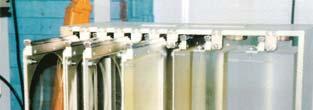
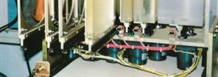
13 The pre-accelerated ions are injected into synchrotrons. There are two synchrotron rings on the lower level and upper level. Circumference is about 130m. Their optical design is normal FODO. The synchrotron can accelerates ions with q/m=1/2 up to 800 MeV/n at the maximum. Synchrotron Injection system 2. Tour Extraction system RF system for acceleration


14 Beam transport line 2. Tour Vertical beam line Horizontal beam line
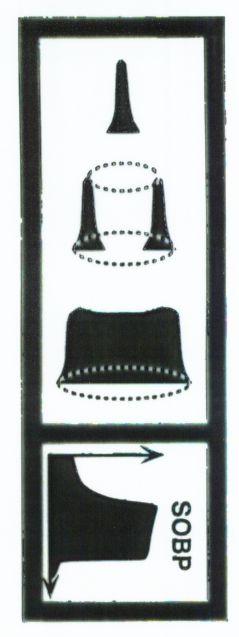
15 Irradiation system 2. Tour Scattering material Dose monitor Wobbling Magnet Ridge Filter Controller Multi Leaf Collimator Range Shifter Cancer Tumor Irradiation area Bolus


16 Treatment room 2. Tour Horizontal port Vertical port

. Almost cases, it takes about 15 minutes.")
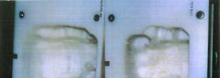
17 Positioning patient 2. Tour A patient must be positioned precisely before the treatment by comparing x-ray radiography image to digitally reconstructed radiography image (DRR). Almost cases, it takes about 15 minutes. On the other hand, irradiation takes about 1~2 minutes. Horizontal & vertical beam port
18 1. Introduction Contents 2. Tour 3. Development of Technologies at 4. Compact Carbon-Therapy Facility 5. New Treatment-Facility Project
19 R&D for Upgrade of Accelerator 3. R&D 1. For increasing irradiation accuracy Gated Irradiation with Patient s Breathing: RF-KO Slow Extraction Improvement of time structure of extracted beam (Reduction of Spill Ripple) Intensity Modulation Delivering high duty beam 2. For increasing efficiency of treatment and study TSA of Injector Automatic beam-axis alignment Intensity Upgrade Development of Ion Source Development of Electron Cooler 3. Development of key technologies of medical accelerator Step-wise variable energy for Injector Development of non-destructive monitors Development of APF-IH Linac Development of Compact ECR Ion Source Compact Carbon-Therapy Machine Development of Compact Un-tuned RF Cavity
20 Intensity Upgrade 3. R&D Intensity should be increasing by suppressing space charge effect, which is effective for the compact synchrotron. Laslett tune shift 2 NRr z p ΔQ A y = 2 3 π b( a + b) β γ Q y 1 B f Under several c-ions, the vertical tune is spread across a few resonance lines, which decreases beam intensity and lifetime!!
21 Transverse Gymnastics - Resonance Correction - 3. R&D Resonance correction by using additional sextupoles Before correction Intensity (10 10 ppp) After correction Intensity (10 10 ppp) Veritcal tune Vertical tune Qx+2Qy=10 Longer lifetime is realized!!
22 To suppress space-charge effect Longitudinal Gymnastics - Multi-Harmonic Acceleration - ΔQ y Bunch Shape 2 NRr z p = A 2 3 π b( a + b) β γ Q Bunching Factor Large Bf Small ΔQ We can obtain beam intensity more than carbons in one cycle. y 1 B f 3. R&D


23 3. R&D Respiration gated irradiation - Irradiation system of coincident with a patient s respiratory motion - Accelerator Interlock system Gated beam extraction system (RF knockout method) Treatment control Watch & record system Gate signal generator Beam monitor Ion beam PSD Respiration waveform Reference Image Compare Positioning Image Planning simulation Positioning area Irradiation room X-ray TV Positioning system using x-ray TV images
24 3. R&D RF-knockout extraction (1) Diffusion by transverse RF-field Frequency modulation (FM) + Constant separatrix Fast response of beam on/off Easy operation Amplitude modulation (AM)
25 3. R&D RF-knockout extraction (2) We have developed the RF-KO slow extraction method, since As a result, we can almost suppress the spill ripple by the dual FM and Separate function methods. NIM-A 522, p.196.

26 3. R&D RF-knockout extraction (3) 80 Boundary of separatrix Counts (arb. unit) n=0 n=10 5 AM func. Feedback r Spill Global Spill Control for RF-KO Assuming radial distribution of particle diffused by RF-KO while keeping Reyleigh distribution, The AM function can be optimized so as to keep the extracted intensity constant. A deviation of the optimized AM function from the true one is corrected by the feedback. The right figure shows an experimental result. As a result, we can obtain the constant intensity in the spill.


27 Global Spill Control and Intensity Modulation 3. R&D f k Function Generators Voltage Controlled Amplifier VCA RF Switch Circulating beam Kicker Electrode V AM RF Amp. AM Function controller Ionization Chanber Scanning Irradiation System Extracted Beam Spill Current Amp 10-6 A/V, 100kHz I T Scanning Magnets Range Shifter I Beam gate Intensity Intensity T
28 1. Introduction Contents 2. Tour 3. Development of Technologies at 4. Compact Carbon-Therapy Facility 5. New Treatment-Facility Project
29 4. Compact Facility Specification 1. Ion species: high LET (100keV/μm) charged particle - Carbon 2. Range: Max. 25cm in water 3. Maximum irradiation area: 15cm square 4. Dose rate: 5Gy/min pps (C ions) 5. Irradiation direction : horizontal, vertical 6. Treatment rooms: 3 (H&V, H, V) 7. Irradiation technique: gating & layer stacking irradiation 1. Accelerator systems and Irradiation systems : High reliability, stability, reproducibility, easy operation, easy maintenance and absolute safety 2. The other requirements : - Precise beam delivering - Easy beam tuning in a short time - Accurate dose measurement and control - Fail-safe system


 0.16 0.12 0.08-0.50-0.25 0 0.25 0.50 0.")


30 4. Compact Facility Design and R&D for Compact Facility Beam Study Compact RF-cavity Compact Injector RFQ + APF-IH Development Irrad. Tech. Intensity (10 10 ppp) Intensity (10 10 ppp) Veritcal tune Vertical tune High-Precision MLC

31 4. Compact Facility Gunma University Heavy-Ion Medical Center Treatment Room Synchrotron 10Ghz-ECR Injector Linac APF-IH


32 4. Compact Facility Gunma University Heavy-Ion Medical Center
33 1. Introduction Contents 2. Tour 3. Development of Technologies at 4. Compact Carbon-Therapy Facility 5. New Treatment-Facility Project


34 Motivation of New Treatment Facility 5. New Project (a) (b) 840cc 69cc Large changing target shape and size We should modify a treatment planning corresponding to change of target during treatment, Adaptive Cancer Treatment

35 Present Method 5. New Project Broad Beam Method with Wobbler and Scatterer Dose distribution is independent of beam quality Easy dose management Low beam-utilization efficiency Extra-dose is given on normal tissue when irregular shape Require Bolus and patient collimator
36 3D Scanning Method 5. New Project Adaptive Therapy by 3D Scanning 1) Beam utilization efficiency 100% 2) Irradiation on irregular shape target 3) No bolus & collimator 1) Depend directly on beam quality 2) Not easy dose management 3) Sensitive to organ motion Scanner Monitor Range Shifter Beam Dose distribution of pencil beam

37 3D organ motion with breathing 5. New Project

 In order to avoid hot/cold spot due to target motion, we decided to employ gating method with")
38 NIRS Simulation of moving tumor irradiation Non-gating Example: Φ40mm spherical target Motion:7mm in gate -40 Gating Moving Tumor Irradiation Fast Scanning is the key technology for completing rescanning within tolerable time. ( πt / 3, φ ) s( t) = cos 2s New Project Gating with rescanning (8 times) In order to avoid hot/cold spot due to target motion, we decided to employ gating method with rescanning
39 Fast scanning for moving target 5. New Project In order to realize the rescanning with gating within acceptable irradiation time, we have studied following strategy. 1. Treatment planning for fast scanning 5 2. Modification of acc. operation 2 3. Fast scanning magnet times speed up of irradiation time

 i T P max 2 u min 2 [ ] [ ( )] max biol, i + U i DP + Q + [ ( ) + ] + P DP U i Dbiol, i w + + QO Dbiol, i w U i DO i O 2 + Predict EDR 0.5 0.4 0.")
40 5. New Project (1) Planning for fast scanning Optimization including the contribution of extra dose in raster scanning Without U i 0.5 Ui Beam intensity y (mm) Fast scanning with beam of high intensity EDR cause dose distortion x (mm) 50 f Cost function : f(w) ( ) o w = Q D ( w) i T P max 2 u min 2 [ ] [ ( )] max biol, i + U i DP + Q + [ ( ) + ] + P DP U i Dbiol, i w + + QO Dbiol, i w U i DO i O 2 + Predict EDR With U i Extra dose in raster scanning (EDR) : U i 0 50

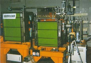
41 (2) Extended FT in Synchrotron 5. New Project SMx Fluorescent screen SMy Beam Syn. BM 1. Treatment planning for fast scanning 5 2. Modification of acc. operation 2 3. Fast scanning magnet 10 Since c-ions is enough high to complete single-fraction, we have employed the extended FT to save the dead time of synchrotron operation. plan


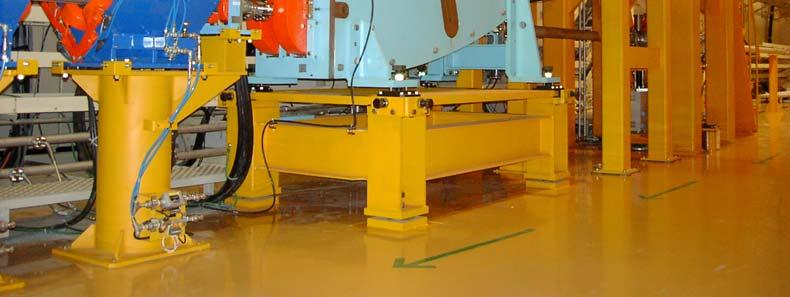
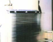
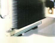
42 5. New Project (3) Fast Scanning Magnet 100mm/ms in H 50mm/ms in V Scanning Magnet Pos. Moni. Dose Moni Range Shifter Since 29 December 2008
+(2) Total time: Scanning time:")

43 Fast 3D-Scanning Experiment 5. New Project (1)+(2) Total time: Scanning time: Range-shifter time: 76 s 64 s 12 s (1)+(2)+(3) Total time: 18.5 s Scanning time: 6. 5 s Range-shifter time:12 s


44 5. New Project 11-steps Energy Operation Toward Variable-Energy 430 MeV Flattop 140 MeV Accel 加速 Decel 減速 入射 Inj Operation Pattern Flattop

 Stored")
45 5. New Project 11-steps Energy Operation C 6+, 290 MeV/n 11-steps Beam Extraction Operation Pattern (SX) Stored Beam Beam Spill
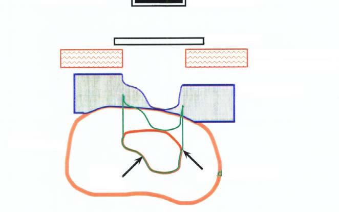
46 Phase-Controlled Raster Scanning Average position of target in each slice is to be Zero one slice with rescanning in one gate y 1st scan 5. New Project respiration signal 6 Gate ON time 3rd scan 2nd scan x averaged distribution displacement (mm) Δr 1 Δr 2 Δr 3 respiration gate -4 1st 2nd 3rd 4th 5th 6th time 1st scan time (s) beam current time z slice No. n n+1 n+2 n+3 scanning trajectory This method needs intensity modulation.


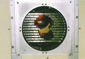
47 5. New Project PCR method ~ experiment Fabrication of moving phantom XY moving stage Wedge for range variation It is possible to operate arbitrary waveform. Screen+CCD system is set on the stage. Specification X and Y direction : ±20mm Range direction : ±17mm (WEL) Max. speed: 40 mm/s


 400 500 12800 15360 16384-50 -100 In this stage, we only")
48 5. New Project PCR method ~ experiment Experimental result Simulation result Non-gating Non-rescanning Non-gating With rescanning (PCR) In this stage, we only tested 2D uniform scanning without gating. Next step is 3D scanning test including non-periodic irregular motion!
49 5. New Project New Treatment Facility: Specification 1. Ion species: 12 C, 16 O ( 11 C, 15 O) 2. Irradiation method: PCR with Gating 3. Range: > 25cm in water 4. Maximum irradiation area: 22cm square for Fixed Port 15cm square for Gantry 5. Delivered Intensity: pps (C ions) 6. Treatment rooms: 2 (H&V), Rotating gantry
: 2")


50 New Treatment Facility (1) 5. New Project 3D Scanning with Gating (H&V): 2 rooms Rotating Gantry : 1 room Research Building for Charged Particle Therapy building Hospital New treatment facility Rotating Gantry Wall RGF QM PRN1 SMx SMy PRN2 RSF 3D Scanning 9.0 m Monitors 0 1 2m Iso-center
51 New Treatment Facility (2) 5. New Project Ground-Breaking Ceremony Construction 19 Feb, 09 6 Feb, 09

52 New Treatment Facility (3) 5. New Project The construction of the new treatment facility will be completed at March New facility building Thanks for your attention!!
53
Development of New Carbon Therapy Facility and Future Plan of HIMAC
 Development of New Carbon Therapy Facility and Future Plan of Koji Noda Research Center for Charged Particle Therapy National Institute of Radiological Sciences 1. Introduction Contents 2. New Carbon-Therapy
Particle Beam Production - A Synchrotron-Based System - Prof. Dr. Thomas Haberer Scientific-technical Director Heidelberg Iontherapy Center
 Particle Beam Production - A Synchrotron-Based System - Prof. Dr. Thomas Haberer Scientific-technical Director Heidelberg Iontherapy Center Outline Situation/Rationale Requirements Synchrotron choice Functions
National Institute of Radiological Sciences. Naoya Saotome
 National Institute of Radiological Sciences Naoya Saotome 1 Contents Introduction History and collaboration KCC i-rock Commissioning of commercial scanning system NIRS Gantry Commissioning of NIRS s Gantry
* National Laboratory for High Energy Physics (KEK) **** Institute for Nuclear Study, University of Tokyo (INS)
 **** Institute for Nuclear Study, University of Tokyo (INS)") Particle Accelerators, 1990, Vol. 33, pp. 147-152 Reprints available directly from the publisher Photocopying permitted by license only 1990 Gordon and Breach, Science Publishers, Inc. Printed in the United
Particle Accelerators, 1990, Vol. 33, pp. 147-152 Reprints available directly from the publisher Photocopying permitted by license only 1990 Gordon and Breach, Science Publishers, Inc. Printed in the United
CERN S PROTON SYNCHROTRON COMPLEX OPERATION TEAMS AND DIAGNOSTICS APPLICATIONS
 Marc Delrieux, CERN, BE/OP/PS CERN S PROTON SYNCHROTRON COMPLEX OPERATION TEAMS AND DIAGNOSTICS APPLICATIONS CERN s Proton Synchrotron (PS) complex How are we involved? Review of some diagnostics applications
Implementing a Proton Beam Scanning System within an Operating Clinical Facility
 Implementing a Proton Beam Scanning System within an Operating Clinical Facility Ben Clasie Many thanks to Hassan Bentefour, Hanne Kooy, and Jay Flanz for their help preparing this presentation 1 Francis
DOSE DELIVERY SYSTEM OF THE VARIAN PROBEAM SYSTEM WITH CONTINUOUS BEAM
 DOSE DELIVERY SYSTEM OF THE VARIAN PROBEAM SYSTEM WITH CONTINUOUS BEAM EUCARD 2 WORKSHOP ON INNOVATIVE DELIVERY SYSTEMS IN PARTICLE THERAPY TORINO, 23 25 FEB 2017 VARIAN PARTICLE THERAPY HOLGER GÖBEL MANGER
III. Proton-therapytherapy. Rome SB - 3/5 1
 Outline Introduction: an historical review I Applications in medical diagnostics Particle accelerators for medicine Applications in conventional radiation therapy II III IV Hadrontherapy, the frontier
The PEFP 20-MeV Proton Linear Accelerator
 Journal of the Korean Physical Society, Vol. 52, No. 3, March 2008, pp. 721726 Review Articles The PEFP 20-MeV Proton Linear Accelerator Y. S. Cho, H. J. Kwon, J. H. Jang, H. S. Kim, K. T. Seol, D. I.
OPERATIONAL EXPERIENCE AT J-PARC
 OPERATIONAL EXPERIENCE AT J-PARC Hideaki Hotchi, ) for J-PARC commissioning team ), 2), ) Japan Atomic Energy Agency (JAEA), Tokai, Naka, Ibaraki, 39-95 Japan, 2) High Energy Accelerator Research Organization
Promises and Perils of Proton Therapy Beam Delivery (Implications) or Towards Cost Effective Particle Therapy
 or Towards Cost Effective Particle Therapy") Promises and Perils of Proton Therapy Beam Delivery (Implications) or Towards Cost Effective Particle Therapy Jay Flanz MGH/FBTC Harvard Medical School What is a Beam Delivery? Start with an accelerator
Promises and Perils of Proton Therapy Beam Delivery (Implications) or Towards Cost Effective Particle Therapy Jay Flanz MGH/FBTC Harvard Medical School What is a Beam Delivery? Start with an accelerator
Present Status and Future Upgrade of KEKB Injector Linac
 Present Status and Future Upgrade of KEKB Injector Linac Kazuro Furukawa, for e /e + Linac Group Present Status Upgrade in the Near Future R&D towards SuperKEKB 1 Machine Features Present Status and Future
PEP II Design Outline
 PEP II Design Outline Balša Terzić Jefferson Lab Collider Review Retreat, February 24, 2010 Outline General Information Parameter list (and evolution), initial design, upgrades Collider Ring Layout, insertions,
Tutorial: Trak design of an electron injector for a coupled-cavity linear accelerator
 Tutorial: Trak design of an electron injector for a coupled-cavity linear accelerator Stanley Humphries, Copyright 2012 Field Precision PO Box 13595, Albuquerque, NM 87192 U.S.A. Telephone: +1-505-220-3975
Recent developments in cyclotrons for proton therapy at IBA
 Recent developments in cyclotrons for proton therapy at IBA Yves Jongen. Founder & CRO IBA sa We Protect, Enhance and Save Lives. A typical PT center 30-55 millions for equipment 45-100 millions for the
Proton Engineering Frontier Project
 Proton Engineering Frontier Project OECD Nuclear Energy Agency Fifth International Workshop on the Utilisation and Reliability of High Power Proton Accelerators (HPPA5) (6-9 May 2007, Mol, Belgium) Yong-Sub
SPEAR 3: Operations Update and Impact of Top-Off Injection
 SPEAR 3: Operations Update and Impact of Top-Off Injection R. Hettel for the SSRL ASD 2005 SSRL Users Meeting October 18, 2005 SPEAR 3 Operations Update and Development Plans Highlights of 2005 SPEAR 3
PRESENT STATUS OF J-PARC
 PRESENT STATUS OF J-PARC # F. Naito, KEK, Tsukuba, Japan Abstract Japan Proton Accelerator Research Complex (J-PARC) is the scientific facility with the high-intensity proton accelerator aiming to realize
The Elettra Storage Ring and Top-Up Operation
 The Elettra Storage Ring and Top-Up Operation Emanuel Karantzoulis Past and Present Configurations 1994-2007 From 2008 5000 hours /year to the users 2010: Operations transition year Decay mode, 2 GeV (340mA)
Low Level RF for PIP-II. Jonathan Edelen LLRF 2017 Workshop (Barcelona) 16 Oct 2017
 16 Oct 2017") Low Level RF for PIP-II Jonathan Edelen LLRF 2017 Workshop (Barcelona) 16 Oct 2017 PIP-II LLRF Team Fermilab Brian Chase, Edward Cullerton, Joshua Einstein, Jeremiah Holzbauer, Dan Klepec, Yuriy Pischalnikov,
Low Level RF for PIP-II Jonathan Edelen LLRF 2017 Workshop (Barcelona) 16 Oct 2017 PIP-II LLRF Team Fermilab Brian Chase, Edward Cullerton, Joshua Einstein, Jeremiah Holzbauer, Dan Klepec, Yuriy Pischalnikov,
Detailed Design Report
 Detailed Design Report Chapter 4 MAX IV Injector 4.6. Acceleration MAX IV Facility CHAPTER 4.6. ACCELERATION 1(10) 4.6. Acceleration 4.6. Acceleration...2 4.6.1. RF Units... 2 4.6.2. Accelerator Units...
Hadron Therapy Technologies
 Hadron Therapy Technologies S. Peggs, BNL & ESS-S Bevalac 1950-1993 Many figures courtesy of Jay Flanz 1 Consumer demand 1 in 3 Europeans will confront some form of cancer in their lifetime. Cancer is
Production of quasi-monochromatic MeV photon in a synchrotron radiation facility
 Production of quasi-monochromatic MeV photon in a synchrotron radiation facility Presentation at University of Saskatchewan April 22-23, 2010 Yoshitaka Kawashima Brookhaven National Laboratory NSLS-II,
STATUS AND CONCEPTUAL DESIGN OF THE CONTROL SYSTEM FOR THE HEAVY ION THERAPY ACCELERATOR FACILITY HICAT
 10th ICALEPCS Int. Conf. on Accelerator & Large Expt. Physics Control Systems. Geneva, 10-14 Oct 2005, PO1.025-1 (2005) STATUS AND CONCEPTUAL DESIGN OF THE CONTROL SYSTEM FOR THE HEAVY ION THERAPY ACCELERATOR
2 Work Package and Work Unit descriptions. 2.8 WP8: RF Systems (R. Ruber, Uppsala)
") 2 Work Package and Work Unit descriptions 2.8 WP8: RF Systems (R. Ruber, Uppsala) The RF systems work package (WP) addresses the design and development of the RF power generation, control and distribution
2 Work Package and Work Unit descriptions 2.8 WP8: RF Systems (R. Ruber, Uppsala) The RF systems work package (WP) addresses the design and development of the RF power generation, control and distribution
New Filling Pattern for SLS-FEMTO
 SLS-TME-TA-2009-0317 July 14, 2009 New Filling Pattern for SLS-FEMTO Natalia Prado de Abreu, Paul Beaud, Gerhard Ingold and Andreas Streun Paul Scherrer Institut, CH-5232 Villigen PSI, Switzerland A new
LCLS RF Reference and Control R. Akre Last Update Sector 0 RF and Timing Systems
 LCLS RF Reference and Control R. Akre Last Update 5-19-04 Sector 0 RF and Timing Systems The reference system for the RF and timing starts at the 476MHz Master Oscillator, figure 1. Figure 1. Front end
RF considerations for SwissFEL
 RF considerations for H. Fitze in behalf of the PSI RF group Workshop on Compact X-Ray Free Electron Lasers 19.-21. July 2010, Shanghai Agenda Introduction RF-Gun Development C-band development Summary
Linac 4 Instrumentation K.Hanke CERN
 Linac 4 Instrumentation K.Hanke CERN CERN Linac 4 PS2 (2016?) SPL (2015?) Linac4 (2012) Linac4 will first inject into the PSB and then can be the first element of a new LHC injector chain. It will increase
A NOVEL GANTRY FOR PROTON THERAPY AT THE PAUL SCHERRER INSTITUTE
 A NOVEL GANTRY FOR PROTON THERAPY AT THE PAUL SCHERRER INSTITUTE E. Pedroni, T. Böhringer, A. Coray, G. Goitein, M. Grossmann, A. Lomax, S. Lin, M. Jermann Paul Scherrer Institute, CH-5232 Villigen PSI,
The FAIR plinac RF Systems
 The FAIR plinac RF Systems Libera Workshop Sep. 2011 Gerald Schreiber Gerald Schreiber, GSI RF Department 2 (1) Overview GSI / FAIR (2) FAIR Proton Linear Accelerator "plinac" (3) plinac RF Systems (4)
Status of SOLARIS Arkadiusz Kisiel
 Status of SOLARIS Arkadiusz Kisiel Solaris National Synchrotron Light Source Jagiellonian University Czerwone Maki 98 30-392 Kraków www.synchrotron.uj.edu.pl Arkadiusz.Kisiel@uj.edu.pl On behalf of SOLARIS
NEW CYCLOTRON DEVELOPMENTS AT IBA
 NEW CYCLOTRON DEVELOPMENTS AT Y. Jongen, W. Kleeven and S.Zaremba, Chemin du Cyclotron 3, B-1348 Louvain-la-Neuve, Belgium Abstract This paper describes some recent cyclotron developments done at - Ion
Quality Assurance Implementation at the Roberts Proton Therapy Center. James McDonough 3 August 2013
 Quality Assurance Implementation at the Roberts Proton Therapy Center James McDonough 3 August 2013 1 Roberts Proton Therapy Center Machine configuration and layout 4 gantries, 1 fixed beam line, 1 research
Commissioning of Accelerators. Dr. Marc Munoz (with the help of R. Miyamoto, C. Plostinar and M. Eshraqi)
") Commissioning of Accelerators Dr. Marc Munoz (with the help of R. Miyamoto, C. Plostinar and M. Eshraqi) www.europeanspallationsource.se 6 July, 2017 Contents General points Definition of Commissioning
Commissioning of Accelerators Dr. Marc Munoz (with the help of R. Miyamoto, C. Plostinar and M. Eshraqi) www.europeanspallationsource.se 6 July, 2017 Contents General points Definition of Commissioning
Current status of XFEL/SPring-8 project and SCSS test accelerator
 Current status of XFEL/SPring-8 project and SCSS test accelerator Takahiro Inagaki for XFEL project in SPring-8 inagaki@spring8.or.jp Outline (1) Introduction (2) Key technology for compactness (3) Key
Beam instrumentation at the 1-MW proton J-PARC RCS
 Beam instrumentation at the 1-MW proton J-PARC RCS HB2014 54th ICFA Advanced Beam Dynamics Workshop on High-Intensity, High-Brightness and High Power Hadron Beams East Lansing, MI Nov.12, 2014 Kazami Yamamoto
EPJ Web of Conferences 95,
 EPJ Web of Conferences 95, 04012 (2015) DOI: 10.1051/ epjconf/ 20159504012 C Owned by the authors, published by EDP Sciences, 2015 The ELENA (Extra Low Energy Antiproton) project is a small size (30.4
Low-Energy Electron Linacs and Their Applications in Cargo Inspection
 Low-Energy Electron Linacs and Their Applications in Cargo Inspection Yawei Yang on behalf of Huaibi Chen *,1, Chuanxiang Tang 1 Yaohong Liu 2 *chenhb@tsinghua.edu.cn 1 Department of Engineering Physics,
LIGHT PROTON THERAPY PROJECT
 17 th of MAY 2018 LIGHT PROTON THERAPY PROJECT Yevgeniy Ivanisenko on behalf of ADAM team FORM-01040-A AVO-ADAM Advanced Oncotherapy (AVO) is a public company ADAM is R&D center of AVO ~ 100 employees
3 cerl. 3-1 cerl Overview. 3-2 High-brightness DC Photocathode Gun and Gun Test Beamline
 3 cerl 3-1 cerl Overview As described before, the aim of the cerl in the R&D program includes the development of critical components for the ERL, as well as the construction of a test accelerator. The
Activities on FEL Development and Application at Kyoto University
 Activities on FEL Development and Application at Kyoto University China-Korea-Japan Joint Workshop on Electron / Photon Sources and Applications Dec. 2-3, 2010 @ SINAP, Shanghai Kai Masuda Inst. Advanced
BEAM DIAGNOSTICS IN THE CNAO INJECTION LINES COMMISSIONING
 BEAM DIAGNOSTICS IN THE CNAO INJECTION LINES COMMISSIONING A. Parravicini, G. Balbinot, J. Bosser, E. Bressi, M. Caldara, L. Lanzavecchia, M. Pullia, M. Spairani, CNAO Foundation, Pavia, Italy C. Biscari,
Studies on an S-band bunching system with hybrid buncher
 Submitted to Chinese Physics C Studies on an S-band bunching system with hybrid buncher PEI Shi-Lun( 裴士伦 ) 1) XIAO Ou-Zheng( 肖欧正 ) Institute of High Energy Physics, Chinese Academy of Sciences, Beijing
New Spill Structure Analysis Tools for the VME Based Data Acquisition System ABLASS at GSI
 New Spill Structure Analysis Tools for the VME Based Data Acquisition System ABLASS at GSI T. Hoffmann, P. Forck, D. A. Liakin * Gesellschaft f. Schwerionenforschung, Planckstr. 1, D-64291 Darmstadt *
COMMISSIONING SCENARIOS FOR THE J-PARC ACCELERATOR COMPLEX
 COMMISSIONING SCENARIOS FOR THE J-PARC ACCELERATOR COMPLEX T. Koseki, M. Ikegami, M. Tomizawa, Accelerator Laboratory, KEK, Tsukuba, Japan F. Noda, JAEA, Tokai, Japan Abstract The J-PARC (Japan Proton
4.4 Injector Linear Accelerator
 4.4 Injector Linear Accelerator 100 MeV S-band linear accelerator based on the components already built for the S-Band Linear Collider Test Facility at DESY [1, 2] will be used as an injector for the CANDLE
G. Pittá(*), S. Braccini TERA Foundation, Novara, Italy (*) Corresponding author.
, S. Braccini TERA Foundation, Novara, Italy (*) Corresponding author.") Frascati Physics Series Vol. VVVVVV (xxxx), pp. 000-000 XX Conference Location, Date-start - Date-end, Year MATRIX: AN INNOVATIVE PIXEL IONIZATION CHAMBER FOR ON-LINE BEAM MONITORING IN HADRONTHERAPY G.
Frascati Physics Series Vol. VVVVVV (xxxx), pp. 000-000 XX Conference Location, Date-start - Date-end, Year MATRIX: AN INNOVATIVE PIXEL IONIZATION CHAMBER FOR ON-LINE BEAM MONITORING IN HADRONTHERAPY G.
Beam Loss Detection for MPS at FRIB
 Beam Loss Detection for MPS at FRIB Zhengzheng Liu Beam Diagnostics Physicist This material is based upon work supported by the U.S. Department of Energy Office of Science under Cooperative Agreement DE-SC0000661.
Bunch-by-bunch feedback and LLRF at ELSA
 Bunch-by-bunch feedback and LLRF at ELSA Dmitry Teytelman Dimtel, Inc., San Jose, CA, USA February 9, 2010 Outline 1 Feedback Feedback basics Coupled-bunch instabilities and feedback Beam and feedback
Top-Up Experience at SPEAR3
 Top-Up Experience at SPEAR3 Contents SPEAR 3 and the injector Top-up requirements Hardware systems and modifications Safety systems & injected beam tracking Interlocks & Diagnostics SPEAR3 Accelerator
An Overview of Beam Diagnostic and Control Systems for AREAL Linac
 An Overview of Beam Diagnostic and Control Systems for AREAL Linac Presenter G. Amatuni Ultrafast Beams and Applications 04-07 July 2017, CANDLE, Armenia Contents: 1. Current status of existing diagnostic
Simulations on Beam Monitor Systems for Longitudinal Feedback Schemes at FLASH.
 Simulations on Beam Monitor Systems for Longitudinal Feedback Schemes at FLASH. Christopher Behrens for the FLASH team Deutsches Elektronen-Synchrotron (DESY) FLS-2010 Workshop at SLAC, 4. March 2010 C.
LLRF at SSRF. Yubin Zhao
 LLRF at SSRF Yubin Zhao 2017.10.16 contents SSRF RF operation status Proton therapy LLRF Third harmonic cavity LLRF Three LINAC LLRF Hard X FEL LLRF (future project ) Trip statistics of RF system Trip
The FLASH objective: SASE between 60 and 13 nm
 Injector beam control studies winter 2006/07 talk from E. Vogel on work performed by W. Cichalewski, C. Gerth, W. Jalmuzna,W. Koprek, F. Löhl, D. Noelle, P. Pucyk, H. Schlarb, T. Traber, E. Vogel, FLASH
BEAM DYNAMICS AND EXPERIMENT OF CPHS LINAC *
 BEAM DYNAMICS AND EXPERIMENT OF CPHS LINAC * L. Du #, C.T. Du, X.L. Guan, C.X. Tang, R. Tang, X.W. Wang, Q.Z. Xing, S.X. Zheng, Key Laboratory of Particle & Radiation Imaging (Tsinghua University), Ministry
LCLS Injector Technical Review
 LCLS Injector Technical Review Stanford Linear Accelerator Center November 3&4 2003 Review Committee Members: Prof. Patrick O Shea Chair University of Maryland Dr. E. Colby Stanford Linear Accelerator
Status of SOLARIS. Paweł Borowiec On behalf of Solaris Team
 Status of SOLARIS Paweł Borowiec On behalf of Solaris Team e-mail: pawel.borowiec@uj.edu.pl XX ESLS-RF Meeting, Villingen 16-17.11.2016 Outline 1. Timeline 2. Injector 3. Storage ring 16-17.11.2016 XX
LHC Beam Instrumentation Further Discussion
 LHC Beam Instrumentation Further Discussion LHC Machine Advisory Committee 9 th December 2005 Rhodri Jones (CERN AB/BDI) Possible Discussion Topics Open Questions Tune measurement base band tune & 50Hz
North Damping Ring RF
 North Damping Ring RF North Damping Ring RF Outline Overview High Power RF HVPS Klystron & Klystron EPICS controls Cavities & Cavity Feedback SCP diagnostics & displays FACET-specific LLRF LLRF distribution
CHAPTER 4: HIGH ENERGY X-RAY GENERATORS: LINEAR ACCELERATORS. Jason Matney, MS, PhD
 CHAPTER 4: HIGH ENERGY X-RAY GENERATORS: LINEAR ACCELERATORS Jason Matney, MS, PhD Objectives Medical electron linear accelerators (often shortened to LINAC) The Basics Power Supply Magnetron/Klystron
Linatron - M9 & M9A. Modular high-energy X-ray source. 2.0 Performance
 The Linatron -M is a modular system. The control console, modulator, and RF unit are common to all model configurations. Only the X-ray head changes to match the application. The Linatron - M is designed
Digital BPMs and Orbit Feedback Systems
 Digital BPMs and Orbit Feedback Systems, M. Böge, M. Dehler, B. Keil, P. Pollet, V. Schlott Outline stability requirements at SLS storage ring digital beam position monitors (DBPM) SLS global fast orbit
Basic rules for the design of RF Controls in High Intensity Proton Linacs. Particularities of proton linacs wrt electron linacs
 Basic rules Basic rules for the design of RF Controls in High Intensity Proton Linacs Particularities of proton linacs wrt electron linacs Non-zero synchronous phase needs reactive beam-loading compensation
A HIGH POWER LONG PULSE HIGH EFFICIENCY MULTI BEAM KLYSTRON
 A HIGH POWER LONG PULSE HIGH EFFICIENCY MULTI BEAM KLYSTRON A.Beunas and G. Faillon Thales Electron Devices, Vélizy, France S. Choroba DESY, Hamburg, Germany Abstract THALES ELECTRON DEVICES has developed
Experience with the Cornell ERL Injector SRF Cryomodule during High Beam Current Operation
 Experience with the Cornell ERL Injector SRF Cryomodule during High Beam Current Operation Matthias Liepe Assistant Professor of Physics Cornell University Experience with the Cornell ERL Injector SRF
Week 0: PPS Certification and Processing. Mon Feb 11 Tue Feb 12 Wed Feb 13 Thu Feb 14 Fri Feb 15 Sat Feb 16 Sun Feb 17
 Week 0: PPS Certification and Processing Mon Feb 11 Tue Feb 12 Wed Feb 13 Thu Feb 14 Fri Feb 15 Sat Feb 16 Sun Feb 17 Work in tunnel Work in tunnel PPS Certification PPS Certification PPS Certification
P. Emma, et al. LCLS Operations Lectures
 P. Emma, et al. LCLS Operations Lectures LCLS 1 LCLS Accelerator Schematic 6 MeV 135 MeV 250 MeV σ z 0.83 mm σ z 0.83 mm σ z 0.19 mm σ δ 0.05 % σ δ 0.10 % σ δ 1.6 % Linac-0 L =6 m rf gun L0-a,b Linac-1
IOT OPERATIONAL EXPERIENCE ON ALICE AND EMMA AT DARESBURY LABORATORY
 IOT OPERATIONAL EXPERIENCE ON ALICE AND EMMA AT DARESBURY LABORATORY A. Wheelhouse ASTeC, STFC Daresbury Laboratory ESLS XVIII Workshop, ELLETRA 25 th 26 th November 2010 Contents Brief Description ALICE
XFEL High Power RF System Recent Developments
 XFEL High Power RF System Recent Developments for the XFEL RF Group Outline XFEL RF System Requirements Overview Basic Layout RF System Main Components Multibeam Klystrons Modulator RF Waveguide Distribution
Jefferson Lab Experience with Beam Halo, Beam Loss, etc.
 Jefferson Lab Experience with Beam Halo, Beam Loss, etc. Pavel Evtushenko with a lot of input from many experienced colleagues Steve Benson, Dave Douglas, Kevin Jordan, Carlos Hernandez-Garcia, Dan Sexton,
Design and Simulation of High Power RF Modulated Triode Electron Gun. A. Poursaleh
 Design and Simulation of High Power RF Modulated Triode Electron Gun A. Poursaleh National Academy of Sciences of Armenia, Institute of Radio Physics & Electronics, Yerevan, Armenia poursaleh83@yahoo.com
Trigger-timing signal distribution system for the KEK electron/positron injector linac
 Trigger-timing signal distribution system for the KEK electron/positron injector linac T. Suwada, 1 K. Furukawa, N. Kamikubota, and M. Satoh, Accelerator Laboratory, High Energy Accelerator Research Organization
LEPTON COLLIDER OPERATION WITH CONSTANT CURRENTS Λ
 SLAC-PUB-11706 LEPTON COLLIDER OPERATION WITH CONSTANT CURRENTS Λ U. Wienands y, SLAC, Stanford, CA, USA Abstract Electron-positron colliders have been operating in a topup-and-coast fashion with a cycle
Joint ICTP/IAEA Advanced School on Dosimetry in Diagnostic Radiology and its Clinical Implementation May 2009
 2033-17 Joint ICTP/ Advanced School on Dosimetry in Diagnostic Radiology and its Clinical Implementation 11-15 May 2009 Dosimetry for CT 3: Practical Experiences Claire-Louise Chapple Freeman Hospital
Upgrading LHC Luminosity
 1 Upgrading LHC Luminosity 2 Luminosity (cm -2 s -1 ) Present (2011) ~2 x10 33 Beam intensity @ injection (*) Nominal (2015?) 1 x 10 34 1.1 x10 11 Upgraded (2021?) ~5 x10 34 ~2.4 x10 11 (*) protons per
45 MW, 22.8 GHz Second-Harmonic Multiplier for High-Gradient Tests*
 US High Gradient Research Collaboration Workshop. SLAC, May 23-25, 2007 45 MW, 22.8 GHz Second-Harmonic Multiplier for High-Gradient Tests* V.P. Yakovlev 1, S.Yu. Kazakov 1,2, and J.L. Hirshfield 1,3 1
DESIGN OF 1.2-GEV SCL AS NEW INJECTOR FOR THE BNL AGS*
 DESIGN OF 1.2-GEV SCL AS NEW INJECTOR FOR THE BNL AGS* A. G. Ruggiero, J. Alessi, M. Harrison, M. Iarocci, T. Nehring, D. Raparia, T. Roser, J. Tuozzolo, W. Weng. Brookhaven National Laboratory, PO Box
Commissioning the TAMUTRAP RFQ cooler/buncher. E. Bennett, R. Burch, B. Fenker, M. Mehlman, D. Melconian, and P.D. Shidling
 Commissioning the TAMUTRAP RFQ cooler/buncher E. Bennett, R. Burch, B. Fenker, M. Mehlman, D. Melconian, and P.D. Shidling In order to efficiently load ions into a Penning trap, the ion beam should be
FIRST SIMULTANEOUS TOP-UP OPERATION OF THREE DIFFERENT RINGS IN KEK INJECTOR LINAC
 FIRST SIMULTANEOUS TOP-UP OPERATION OF THREE DIFFERENT RINGS IN KEK INJECTOR LINAC M. Satoh #, for the IUC * Accelerator Laboratory, High Energy Accelerator Research Organization (KEK) 1-1 Oho, Tsukuba,
KEKB INJECTOR LINAC AND UPGRADE FOR SUPERKEKB
 KEKB INJECTOR LINAC AND UPGRADE FOR SUPERKEKB S. Michizono for the KEK electron/positron Injector Linac and the Linac Commissioning Group KEK KEKB injector linac Brief history of the KEK electron linac
Mechanical aspects, FEA validation and geometry optimization
 RF Fingers for the new ESRF-EBS EBS storage ring The ESRF-EBS storage ring features new vacuum chamber profiles with reduced aperture. RF fingers are a key component to ensure good vacuum conditions and
THE IBA SUPERCONDUCTING SYNCHROCYCLOTRON PROJECT S2C2
 THE IBA SUPERCONDUCTING SYNCHROCYCLOTRON PROJECT S2C2 W. Kleeven, M. Abs, E. Forton, S. Henrotin, Y. Jongen, V. Nuttens, Y. Paradis, E. Pearson, S. Quets, J. Van de Walle, P. Verbruggen, S. Zaremba, IBA,
CLIC Feasibility Demonstration at CTF3
 CLIC Feasibility Demonstration at CTF3 Roger Ruber Uppsala University, Sweden, for the CLIC/CTF3 Collaboration http://cern.ch/clic-study LINAC 10 MO303 13 Sep 2010 The Key to CLIC Efficiency NC Linac for
Photoinjector Laser Operation and Cathode Performance
 Photoinjector Laser Operation and Cathode Performance Daniele Sertore, INFN Milano LASA Siegfried Schreiber, DESY Laser operational experience Laser beam properties Cathode performances Outlook TTF and
RF Power Generation II
 RF Power Generation II Klystrons, Magnetrons and Gyrotrons Professor R.G. Carter Engineering Department, Lancaster University, U.K. and The Cockcroft Institute of Accelerator Science and Technology Scope
Advanced Photon Source - Upgrades and Improvements
 Advanced Photon Source - Upgrades and Improvements Horst W. Friedsam, Jaromir M. Penicka Argonne National Laboratory, Argonne, Illinois, USA 1. INTRODUCTION The APS has been operational since 1995. Recently
Design Studies For The LCLS 120 Hz RF Gun Injector
 BNL-67922 Informal Report LCLS-TN-01-3 Design Studies For The LCLS 120 Hz RF Gun Injector X.J. Wang, M. Babzien, I. Ben-Zvi, X.Y. Chang, S. Pjerov, and M. Woodle National Synchrotron Light Source Brookhaven
Beam Instrumentation for CTF3 and CLIC
 Beam Instrumentation for CTF3 and CLIC Beam loss - Beam halo monitoring developments CLIC diagnostic Common developments with other projects Specific requirements for CLIC Beam Loss and Beam Halo measurement
Equipment Installation, Planning, Layout, organisation and updates
 Equipment Installation, Planning, Layout, organisation and updates Simon Mataguez, Julie Coupard with contributions of the LIU-PLI team Table of contents: LIU installation activities Organisation of the
Oak Ridge Spallation Neutron Source Proton Power Upgrade Project and Second Target Station Project
 Oak Ridge Spallation Neutron Source Proton Power Upgrade Project and Second Target Station Project Workshop on the future and next generation capabilities of accelerator driven neutron and muon sources
Electrical and Electronic Laboratory Faculty of Engineering Chulalongkorn University. Cathode-Ray Oscilloscope (CRO)
") 2141274 Electrical and Electronic Laboratory Faculty of Engineering Chulalongkorn University Cathode-Ray Oscilloscope (CRO) Objectives You will be able to use an oscilloscope to measure voltage, frequency
2141274 Electrical and Electronic Laboratory Faculty of Engineering Chulalongkorn University Cathode-Ray Oscilloscope (CRO) Objectives You will be able to use an oscilloscope to measure voltage, frequency
P. Adamson, Fermi National Accelerator Laboratory, Batavia, IL 60510, USA. Abstract
 Abstract 7 0 0 k W M A I N I N J E C T O R O P E R A T I O N S F O R N O νa AT FNAL P. Adamson, Fermi National Accelerator Laboratory, Batavia, IL 60510, USA Following a successful career as an antiproton
The basic parameters of the pre-injector are listed in the Table below. 100 MeV
 3.3 The Pre-injector The high design brightness of the SLS requires very high phase space density of the stored electrons, leading to a comparatively short lifetime of the beam in the storage ring. This,
Status of RF Power and Acceleration of the MAX IV - LINAC
 Status of RF Power and Acceleration of the MAX IV - LINAC Dionis Kumbaro ESLS RF Workshop 2015 MAX IV Laboratory A National Laboratory for synchrotron radiation at Lunds University 1981 MAX-lab is formed
RF Power Klystrons & 20 Year Look. R. Nelson 7/15/15
 RF Power Klystrons & 20 Year Look R. Nelson 7/15/15 RF Power klystrons 8 x 13 kw klystrons Page 2 Why A klystron? Best (only) choice at the time - 1988 Easy to use: Input (drive), output (to CM), power
Linac3 experience for LHC ion runs
 Linac3 experience for LHC ion runs G Bellodi for the Linac3 team Keywords: beam performance reliability set up time results of MDs remaining unknowns 1 A year in perspective Source removed: change of main
Summary of the 1 st Beam Line Review Meeting Injector ( )
") Summary of the 1 st Beam Line Review Meeting Injector (23.10.2006) 15.11.2006 Review the status of: beam dynamics understanding and simulations completeness of beam line description conceptual design of
Summary of the 1 st Beam Line Review Meeting Injector (23.10.2006) 15.11.2006 Review the status of: beam dynamics understanding and simulations completeness of beam line description conceptual design of
THE OPERATION EXPERIENCE AT KOMAC*
 THAM2X01 Proceedings of HB2016, Malmö, Sweden THE OPERATION EXPERIENCE AT KOMAC* Yong-Sub Cho, Kye-Ryung Kim, Kui Young Kim, Hyeok-Jung Kwon, Han-Sung Kim, Young-Gi Song Korea Atomic Energy Research Institute,
Development of an Abort Gap Monitor for High-Energy Proton Rings *
 Development of an Abort Gap Monitor for High-Energy Proton Rings * J.-F. Beche, J. Byrd, S. De Santis, P. Denes, M. Placidi, W. Turner, M. Zolotorev Lawrence Berkeley National Laboratory, Berkeley, USA