Preface. About SunFounder. About Super Kit. Free Support
|
|
|
- Elizabeth Paulina Wilkerson
- 5 years ago
- Views:
Transcription
1 About SunFounder Preface SunFounder is a technology company focused on Raspberry Pi and Arduino open source community development. Committed to the promotion of open source culture, we strive to bring the fun of electronics making to people all around the world and enable everyone to be a maker. Our products include learning kits, development boards, robots, sensor modules and development tools. In addition to high quality products, SunFounder also offers video tutorials to help you build your own project. If you have interest in open source or making something cool, welcome to join us! Visit for more! About Super Kit The super kit is suitable for the SunFounder Uno, SunFounder Mega 2560, SunFounder Duemilanove, and SunFounder Nano. All the code included in this kit works with these boards. Our SunFounder board is fully compatible with Arduino. With this kit, we will walk you through the know-how of using the SunFounder board in a hands-on way. Starting with the basics of electronics, you'll learn through building several creative projects. Including a selection of the most common and useful electronic components, this kit will help you "control" the physical world. In this book, we will show you circuits with both realistic illustrations and schematic diagrams. You can go to our official website to download related code by clicking LEARN -> Get Tutorials and watch videos under VIDEO. Free Support If you have any TECHNICAL questions, add a topic under FORUM section on our website and we'll reply as soon as possible. For NON-TECH questions like order and shipment issues, please send an to service@sunfounder.com. You're also welcomed to share your projects on FORUM. Rept 4.0
2 Contents Components List... 1 Notice... 7 Lesson 1 Blinking LED...9 Lesson 2 Controlling an LED by Button Lesson 3 Controlling an LED by PWM...16 Lesson 4 Controlling an LED by Potentiometer...21 Lesson 5 Flowing LED Lights...24 Lesson 6 RGB LED...27 Lesson 7 DC Motor Control...30 Lesson 8 LCD Lesson 9 Serial Monitor Lesson 10 7-Segment Display Lesson 11 74HC Lesson 12 Dot Matrix LED Display Lesson 13 NE555 Timer...56 Lesson 14 Rotary Encoder...60 Lesson 15 ADXL Lesson 16 Simple Creation - Light Alarm...68 Lesson 17 Simple Creation - Traffic Light...71 Lesson 18 Simple Creation - Digital Dice Lesson 19 Simple Creation - Small Fan... 76
3


4 Components List No. Name Qty. Component 1 RGB LED Timer IC 1 3 Optocoupler (4N35) 2 4 Shift Register (74HC595) 2 5 L293D 1 1
 5 9 Resistor (220Ω) 8 (red, red,")
 11 Resistor (10kΩ) 4 (brown,")
 13 Resistor (5.")
5 6 Accelerometer ADXL Rotary Encoder 1 8 Push-Button (small) 5 9 Resistor (220Ω) 8 (red, red, black, black, brown) 10 Resistor (1kΩ) 4 (brown, black, black, brown, brown) 11 Resistor (10kΩ) 4 (brown, black, black, red, brown) 12 Resistor (1MΩ) 1 (brown, black, green, gold) 13 Resistor (5.1MΩ) 1 (green, brown, green, gold) 2


6 14 Switch 1 15 Potentiometer (50kΩ) *2 LCD Character Display *8 Dot-Matrix Display Segment Character Display 2 3
")
 2 22")


7 19 DC Motor 1 20 LED (red) LED (white) 2 22 LED (green) 2 23 LED (yellow) 2 24 NPN Transistor (S8050) 2 4
 2 26")

 4 29")

8 25 PNP Transistor (S8550) 2 26 Capacitor Ceramic 100nF 4 27 Capacitor Ceramic 10nF 4 28 Diode Rectifier (1N4007) 4 29 Breadboard 1 30 USB Cable 1 5
 65 32 Dupont Wire")


9 31 Jumper Wire (Male to Male) Dupont Wire (Female to Male) Passive Buzzer 1 34 Fan 1 Note: After unpacking, please check that the number of components is correct and that all components are in good condition. 6

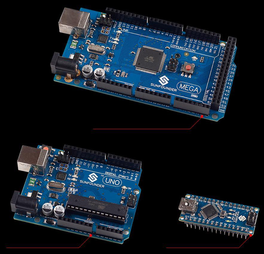
10 Notice All the experiments in this kit are done with SunFounder Uno R3 board, but they are also compatible with SunFounder Mega 2560, SunFounder Nano and all official Arduino Boards. All the code included in this kit works with these boards. So what does COMPATIBLE mean here? It means you can use any of the three boards to do the same experiment with the same wiring. Take turning on an LED as an example. We use SunFounder Uno as the microcontroller, but you can also use SunFounder Nano or SunFounder Mega 2560 to serve the same function. Just select the right Board and COM when compiling. 7
11 8
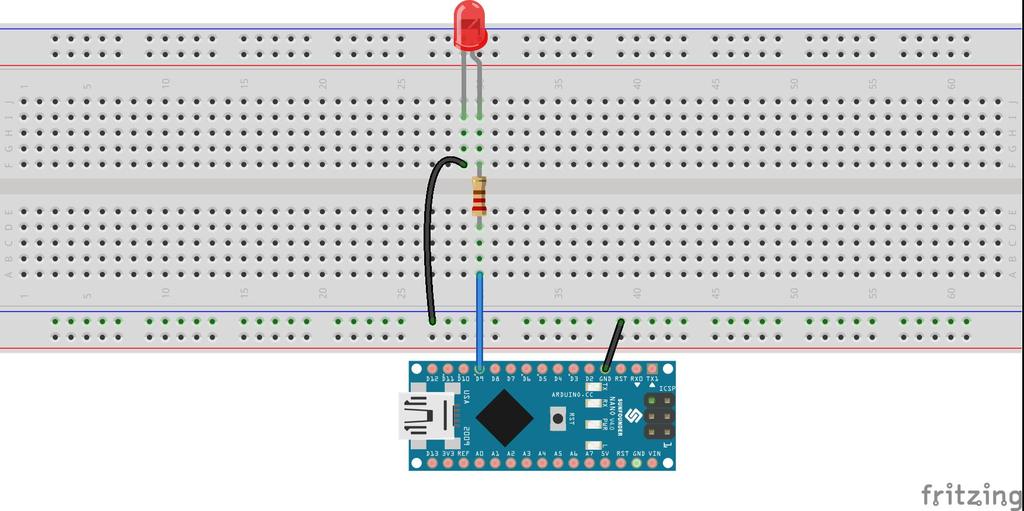
12 Lesson 1 Blinking LED Introduction In this lesson, you will learn how to use the SunFounder Uno board by turning on an LED and making it blink once per second. Components - 1 * SunFounder Uno board - 1 * USB cable - 1 * Resistor (220Ω) - 1 * 1 LED - 1 * Breadboard - Jumper wires Principle LED A light-emitting diode (LED) is a semiconductor device which can turn electric energy into light energy via PN junctions. By wavelength, it can be categorized into laser diode, infrared light-emitting diode and visible light-emitting diode which is usually known as lightemitting diode (LED). LEDs are usually red, yellow, green, blue, or color-changing --- their color varies with different voltages. Before building any circuit, you should know the parameters of the components in the circuit, such as their operating voltage, operating circuit, etc. A current-limiting resistor should be connected when an LED is used; or else the LED can be burnt due to excessive currents. In this experiment, the operating voltage of the LED is between 1.5V and 2.0V and the operating current is 10mA - 20mA. The SunFounder Uno board can supply 5V power, the LED we choose works at 1.7V, 15mA. The current-limiting resistance equals total voltage subtracted by LED voltage, then divided by current. In this case, that would be (5-1.7)/ Thus, the current-limiting resistance equals 220Ω. 9
13 Experimental Procedures Step 1: Build the circuit The schematic diagram 10
14 Step 2: Program (Please refer to the example code in LEARN -> Get Tutorials on our website) Step 3: Compile the code Step 4: Upload the sketch to the SunFounder Uno board You should now see the LED blinking. Experimental Summary Through this experiment, you have learned how to turn on an LED. You can also change the blinking frequency of the LED by changing the num value in the delay function delay (num). For example, change it to delay (250) and you will find that the LED blinks more quickly. Tips: For any TECHNICAL questions, add a topic under FORUM section on our website and we'll reply as soon as possible. For NON-TECH questions like order issues, please service@sunfounder.com. 11

 - 1 * Breadboard - Jumper wires Principle Button Buttons are a common component used to control electronic")
15 Lesson 2 Controlling an LED by Button Introduction In this experiment, you will learn how to turn on/off an LED by using an I/O port and a button. The "I/O port" refers to the INPUT and OUTPUT port. Here the INPUT port of the SunFounder Uno board is used to read the output of an external device. Since the board itself has an LED (connected to Pin 13), you can use this LED to do this experiment for convenience. Components - 1 * SunFounder Uno board - 1 * USB cable - 1 * Button - 1 * Resistor (10kΩ) - 1 * Breadboard - Jumper wires Principle Button Buttons are a common component used to control electronic devices. They are usually used as switches to connect or break circuits. Although buttons come in a variety of sizes and shapes, the one used here is a 6mm mini-button as shown in the following pictures. Pins pointed out by the arrows of same color are meant to be connected. Front Back 12
16 When the button is pressed, the pins pointed by the blue arrow will connect to the pins pointed by the red arrow (see the above figure), thus closing the circuit, as shown in the following diagrams. Generally, the button can be connected directly to the LED in a circuit to turn on or off the LED, which is comparatively simple. However, sometimes the LED will brighten automatically without any button pressed, which is caused by various kinds of external interference. In order to avoid this interference, a pull-down resistor is used usually connect a 1K 10KΩ resistor between the button and GND. It can be connected to GND to consume the interference when the button is off. This circuit connection is widely used in numerous circuits and electronic devices. We may use the button to control a circuit later in many experiments (in or outside this kit maybe), so you might get its principle, which is very simple, and application at the beginning of your study. 13


17 Experimental Procedures Step 1: Build the circuit The schematic diagram 14

18 Step 2: Program (Please refer to the example code in LEARN -> Get Tutorials on our website) Step 3: Compile the code Step 4: Upload the sketch to the SunFounder Uno board Now, press the button, and the LED on the SunFounder Uno board will light up. 15
19 Lesson 3 Controlling an LED by PWM Introduction In this lesson, let s try something interesting gradually changing the luminance of an LED through programming. Since the pulsing light looks like breathing, we give it a magical name - breathing LED. We ll accomplish this effect with pulse width modulation (PWM). Components - 1 * SunFounder Uno board - 1 * Breadboard - 1 * LED - 1 * Resistor (220Ω) - 1 * USB cable - Jumper wires Principle PWM Pulse width modulation, or PWM, is a technique for getting analog results with digital means. Digital control is used to create a square wave, a signal switched between on and off. This on-off pattern can simulate voltages in between full on (5 Volts) and off (0 Volts) by changing the portion of the time the signal spends on versus the time that the signal spends off. The duration of "on time" is called pulse width. To get varying analog values, you change, or modulate, that width. If you repeat this on-off pattern fast enough with some device, an LED for example, it would be like this: the signal is a steady voltage between 0 and 5V controlling the brightness of the LED. (See the PWM description on the official website of Arduino). 16
20 We can see from the top oscillogram that the amplitude of the DC voltage output is 5V. However, the actual voltage output is only 3.75V through PWM because the high level only takes up 75% of the total voltage within a period. Here is an introduction to the three basic parameters of PWM: 1. Duty cycle describes the proportion of "on" time to the regular interval or period of time. 2. Period describes the reciprocal of pulses in one second. 17
21 3. The voltage amplitude here is 0V 5V. In this experiment, we use this technology to make the LED brighten and dim slowly so it looks like our breath. 18

22 Experimental Procedures Step 1: Build the circuit The schematic diagram 19
23 Step 2: Program (Please refer to the example code in LEARN -> Get Tutorials on our website) Step 3: Compile the code Step 4: Upload the sketch to the SunFounder Uno board Here you should see the LED gets brighter and brighter, then slowly dimmer, and again brighter and dimmer repeatedly, just like breathing. 20
24 Lesson 4 Controlling an LED by Potentiometer Introduction In the previous experiment, you have learned how to control an LED by PWM programming, which is interesting though sounds slightly abstract. In this lesson, let's see how to change the luminance of an LED by a potentiometer. Components - 1 * SunFounder Uno board - 1 * Breadboard - 1 * Resistor (220Ω) - 1 * LED - 1 * Potentiometer - 1 * USB cable - Jumper wires Principle Analog V.S. Digital A linear potentiometer is an analog electronic component. So what s the difference between an analog value and a digital one? Simply put, digital means on/off, high/low level with just two states, i.e. either 0 or 1. But the data state of analog signals is linear, for example, from 1 to 1000; the signal value changes over time instead of indicating an exact number. Analog signals include those of light intensity, humidity, temperature, and so on. In this experiment, a potentiometer, or pot, is used to change the current in the circuit so the luminance of the LED will change accordingly. And since the pot is an analog device, the current change is smooth, thus the LED will gradually get brighter or dimmer instead of going through an obvious stepwise process. What we mean by PWM here is the digitalization of analog signals, which is a process of approaching analog signals. Since the potentiometer inputs analog signals, it should be connected to analog ports, i.e. A0-A5 of the Uno board, instead of digital ports. 21
25 Experimental Procedures Step 1: Build the circuit The schematic diagram 22

26 As you can see, the potentiometer is connected to pin A0 of the SunFounder Uno board, which can measure voltages from 0V to 5V. The corresponding value returned is from 0 to The measurement accuracy for voltage change is relatively high. Step 2: Program (Please refer to the example code in LEARN -> Get Tutorials on our website) Step 3: Compile the code Step 4: Upload the sketch to the SunFounder Uno board Spin the shaft of the potentiometer and you should see the luminance of the LED change. 23

27 Lesson 5 Flowing LED Lights Introduction In this lesson, we will conduct a simple yet interesting experiment using LEDs to create flowing LED lights. As the name suggests, these eight LEDs in a row successively light up and dim one after another, just like flowing water. Components - 1 * SunFounder Uno board - 1 * Breadboard - 8 * LED - 8 * Resistor (220Ω) - 1 * USB cable - Jumper wires Principle The principle of this experiment is simply to turn on eight LEDs in turn. Experimental Procedures Step 1: Build the circuit 24


28 The schematic diagram Step 2: Program (Please refer to the example code in LEARN -> Get Tutorials on our website) Step 3: Compile the code Step 4: Upload the sketch to the SunFounder Uno board 25

29 Now, you should see eight LEDs brighten one by one from left to right, and then dim in turn from right to left. After that, the LEDs will light up from right to left and dim from left to right. This whole process will repeat until the circuit is power off. 26
30 Lesson 6 RGB LED Introduction Previously we've used the PWM technology to control an LED brighten and dim. In this lesson, we will use it to control an RGB LED to flash various kinds of color. Components - 1 * RGB LED - 3 * Resistor (220Ω) - 1 * Breadboard - 1 * SunFounder Uno board - 1 * USB cable - Jumper wires Principle RGB RGB stands for the red, green, and blue color channels and is an industry color standard. RGB displays various new colors by changing the three channels and superimposing them, which, according to statistics, can create 16,777,216 different colors. Each of the three color channels has 255 stages of brightness. When the three primary colors are all 0, it is the least bright, thus turning it off. When the three colors are all 255, which is the brightest, the LEDs will brighten. When the light emitted of the three colors are mixed together, the colors will be mixed too. However, the brightness is equal to the sum of all brightness. And the more you mix, the brighter the LED gets. This process is known as additive mixing. In this experiment, we will also use PWM which, if you ve followed the lessons thus far, you already have a basic understanding of. Here we input a value between 0 and 255 to the three pins of the RGB LED to make it display different colors. 27


31 Experimental Procedures Step 1: Build the circuit The schematic diagram 28
32 Step 2: Program (Please refer to the example code in LEARN -> Get Tutorials on our website) Step 3: Compile the code Step 4: Upload the sketch to the SunFounder Uno board Here you should see the RGB LED flash circularly red, green, and blue first, then red, orange, yellow, green, blue, indigo, and purple. 29
33 Lesson 7 DC Motor Control Introduction In this experiment, we will learn how to control the direction and speed of a small-sized DC motor by a driver chip L293D and the SunFounder Uno board. Making simple experiments, we will just make the motor rotate left and right, and accelerate or decelerate automatically. Components - 1 * Small-sized DC motor - 1 * L293D - 1 * SunFounder Uno board - 1 * Breadboard - 1 * USB cable - Jumper wires Principle L293D This is a very practical chip that can independently control two DC motors. In this experiment, just about half of the chip is used most pins on the right side of the chip are used to control a second motor, which is not needed since we apply only one motor here. L293D has two pins (Vcc1 and Vcc2) for power supply. Vcc2 is used to supply power for the motor, while Vcc1 to supply for the chip. Since a small-sized DC motor is used here, connect both pins to +5V. If you use a higher power motor, you need to connect Vcc2 to 30
34 an external power supply. At the same time, the GND of L293D should be connected to that of the SunFounder Uno board. DC Motor Specifications Voltage: 3-6V Main Size: length 25mm, thickness 15mm, width 20mm Motor Shaft Length: 9mm, Shaft Diameter 2mm Rated Voltage: 3v Reference Current: A 3v Rotating Speed: RPM Experimental Procedures Step 1: Build the circuit 31
 Step 3: Compile the code Step")

35 The schematic diagram Step 2: Program (Please refer to the example code in LEARN -> Get Tutorials on our website) Step 3: Compile the code Step 4: Upload the sketch to the SunFounder Uno board The blade of the DC motor will begin rotating left and right, in a speed that varies accordingly. 32
36 33
37 Lesson 8 LCD1602 Introduction In this experiment, the SunFounder Uno board is used to directly drive LCD1602 to display characters. Components - 1 * SunFounder Uno board - 1 * Breadboard - 1 * LCD * Potentiometer (50kΩ) - 1 * USB cable - Jumper wires Principle Generally, LCD1602 has parallel ports, that is, it would control several pins at the same time. LCD1602 can be categorized into eight-port and four-port connections. If the eight-port connection is used, then all the digital ports of the SunFounder Uno board are almost completely occupied. If you want to connect more sensors, there will be no ports available. Therefore, the four-port connection is used here for better application. Pins of LCD1602 and their functions VSS: connected to ground VDD: connected to a +5V power supply VO: to adjust the contrast RS: A register select pin that controls where in the LCD s memory you are writing data to. You can select either the data register, which holds what goes on the screen, or an instruction register, which is where the LCD s controller looks for instructions on what to do next. R/W: A Read/Write pin to select between reading and writing mode E: An enabling pin that, when low-level energy is supplied, causes the LDC module to execute relevant instructions. D0-D7: to read and write data A and K: Pins that control the LCD backlight In this experiment, a 50KΩ potentiometer is used to adjust the contrast of LCD1602 to display characters or figures as you want. For programming, it is optimized by calling function libraries. 34


38 Experimental Procedures Step 1: Build the circuit (please be sure the pins are connected correctly. Otherwise, characters will not be displayed properly): The schematic diagram 35

39 Step 2: Program (Please refer to the example code in LEARN -> Get Tutorials on our website) Step 3: Compile Step 4: Upload the sketch to the SunFounder Uno board Note: you may need to adjust the potentiometer on the LCD1602 until it can display clearly. You should now see the characters "SunFounder" and "hello, world" rolling on the LCD. 36
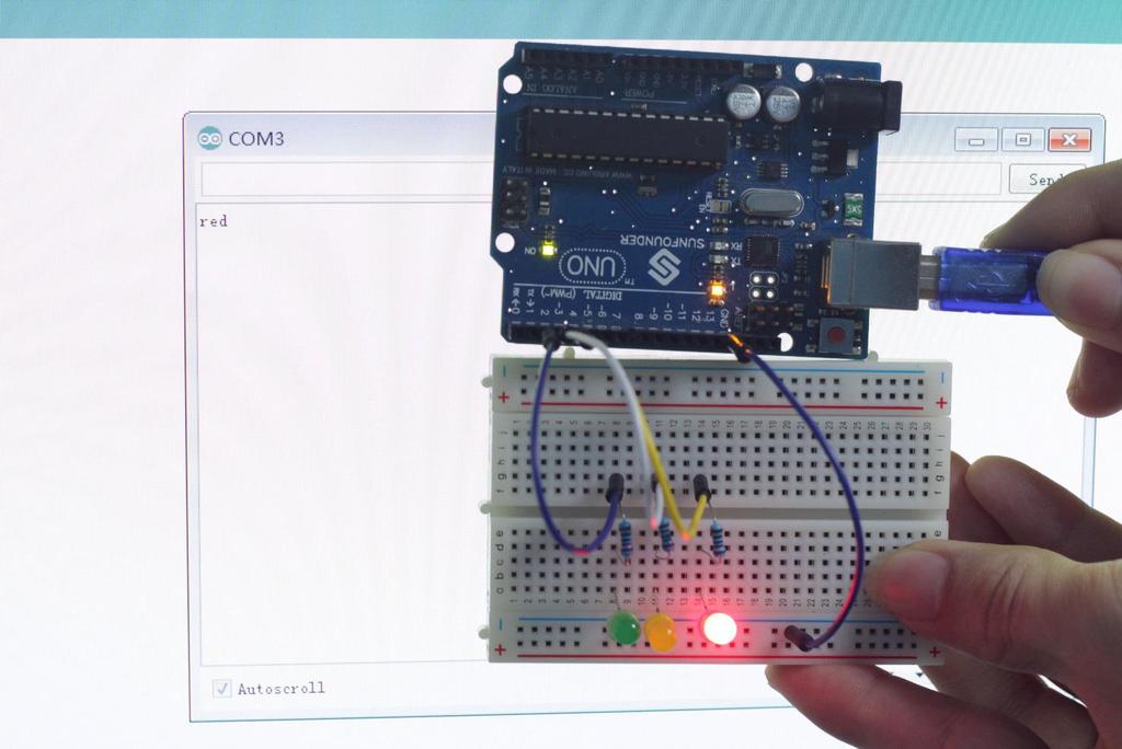
40 Lesson 9 Serial Monitor Introduction In this experiment, you will learn how to turn on or off LEDs through a computer and the Serial Monitor. Serial Monitor is used for communication between the Uno board and a computer or other devices. It is a built-in software in the Arduino environment and you can click the button on the upper right corner to open it. You can send and receive data via the serial port on the Uno board and control the board by input from the keyboard. In this experiment, since we use colored LEDs as loads, you can enter a color among red, green, and blue on Serial Monitor in the IDE. The corresponding LED on the SunFounder Uno board will then light up. Components - 1 * SunFounder Uno board - 1 * Breadboard - 3 * LED - 3 * Resistor (220Ω) - 1 * USB cable - Jumper wires Principle Here, the Serial Monitor serves as a transfer station for communication between your computer and the SunFounder Uno board. First, the computer transfers data to the Serial Monitor, and then the data is read by the Uno board. Finally, the Uno will perform related operations. 37

41 Experimental Procedures Step 1: Build the circuit The schematic diagram 38
42 Step 2: Program (Please refer to the example code in LEARN -> Get Tutorials on our website) Step 3: Compile the code Step 4: Upload the sketch to the SunFounder Uno board Now, click the Serial Monitor button at the upper right corner in the IDE. Then the Serial Monitor window will pop up as shown below. 39
43 With this window, you can not only send data from your computer to the SunFounder Uno board, but also receive data from the board and display it on the screen. When you open the window, it will display "Please input any color of LED:". You can input a color here. If you enter red, green, or blue, click Send, then the corresponding LED on the breadboard will light up. However, if you enter any other colors, no LEDs will brighten. For example, if you input red, you will see the red LED light up. 40
44 41

45 Lesson 10 7-Segment Display Introduction A 7-segment display is a device that can display numerals and letters. It's made up of seven LEDs connected in parallel. Different letters/numbers can be shown by connecting pins on the display to the power source and enabling the related pins, thus turning on the corresponding LED segments. In this lesson we will learn how to use it to display specific characters. Components - 1 * SunFounder Uno board - 1 * 7-segment display (Common Cathode) - 8 * Resistor (220Ω) - 1 * USB cable - 1 * Breadboard - Jumper wires Principle 7-Segment Display A 7-segment display is an 8-shaped component which packages 7 LEDs. Each LED is called a segment when energized, one segment forms part of a numeral (both decimal and hexadecimal) to be displayed. An additional 8th LED is sometimes used within the same package thus allowing the indication of a decimal point (DP) when two or more 7-segment displays are connected together to display numbers greater than ten. Each of the LEDs in the display is given a positional segment with one of its connection pins led out from the rectangular plastic package. These LED pins are labeled from "a" through to "g" representing each individual LED. The other LED pins are connected together forming a common pin. So by forward biasing the appropriate pins of the LED segments in a particular order, some segments will brighten and others stay dim, thus showing the corresponding character on the display. 42
 and Common Anode (CA).")
46 The common pin of the display generally tells its type. There are two types of pin connection: a pin of connected cathodes and one of connected anodes, indicating Common Cathode (CC) and Common Anode (CA). As the name suggests, a CC display has all the cathodes of the 7 LEDs connected when a CA display has all the anodes of the 7 segments connected. Common Cathode 7-Segment Display In a common cathode display, the cathodes of all the LED segments are connected to the logic "0" or ground. Then an individual segment (a-g) is energized by a "HIGH", or logic "1" signal via a current limiting resistor to forward bias the anode of the segment. Common Anode 7-Segment Display In a common anode display, the anodes of all the LED segments are connected to the logic "1". Then an individual segment (a-g) is energized by a ground, logic "0" or "LOW" signal via a current limiting resistor to the cathode of the segment. 43
47 Experimental Procedures Step 1: Build the circuit (here a common cathode 7-segment display is used) The wiring between the 7-segment display and the SunFounder Uno board is as shown below: 7-Segment Display SunFounder Uno Board a 7 b 6 c 5 d 11 e 10 f 8 g 9 dp 4 - GND 44
 Step 3: Compile the")

48 The schematic diagram Step 2: Program (Please refer to the example code in LEARN -> Get Tutorials on our website) Step 3: Compile the code Step 4: Upload the sketch to the SunFounder Uno board You should now see the 7-segment display from 0 to 9 and then A to F, back and forth. 45
49 46

50 Lesson 11 74HC595 Introduction Generally, there are two ways to drive a single 7-segment display. One way is to connect its 8 pins directly to eight ports on the SunFounder Uno board, which we have done previously. Or you can connect the 74HC595 to three ports of the Uno board and then the 7-segment display to the 74HC595. In this experiment, we will use the latter. By this way, we can save five ports considering the Uno board s limited ports, this is very important. Now let's get started! Components - 8 * Resistor (220Ω) - 1 * 74HC595-1 * SunFounder Uno board - 1 * Breadboard - 1 * USB cable - 1 * 7-segment display - Jumper wires Principle 74HC595 The 74HC595 consists of an 8 bit shift register and a storage register with three state parallel outputs. It converts serial input into parallel output so that you can save IO ports of an MCU. The 74HC595 is widely used to indicate multipath LEDs and drive multi-bit segment displays. "Three-state" mentioned above refers to the fact that you can set the output pins as either high, low or high impedance. With data latching, the instant output will not be affected during the shifting; with data output, you can cascade 74HC595s more easily. 47
51 Pins of 74HC595 and their functions: Q0-Q7: 8-bit parallel data output pins, able to control 8 LEDs or 8 pins of 7-segment display directly. Q7 : Series output pin, connected to DS of another 74HC595 to connect multiple 74HC595s in series MR: Reset pin, active at low level; here it is directly connected to 5V. SH: Time sequence input of shift register. On the rising edge, the data in shift register moves successively one bit, i.e. data in Q1 moves to Q2, and so forth. While on the falling edge, the data in shift register remain unchanged. ST: Time sequence input of storage register. On the rising edge, data in the shift register moves into memory register. OE: Output enable pin, active at low level, connected to GND. DS: Serial data input pin VCC: Positive supply voltage GND: Ground Here a function shiftout() is used, which comes with the Arduino IDE. Simply input a number between 0 and 255 and the storage register can convert it into an 8-bit binary number and output it in parallel. This allows you to easily control the 8 pins of the 7-segment display and create any patterns you want. Experimental Procedures Step 1: Build the circuit 7-Segment Display 74HC595 SunFounder Uno R3 a b c d e f g DP Q7 Q6 Q5 Q4 Q3 Q2 Q1 Q0 48
52 VCC 5V DS 11 CE GND ST 12 SH 8 MR 5V Q7 N/C GND GND - GND 49
 Step 3:")

53 The schematic diagram Step 2: Program (Please refer to the example code in LEARN -> Get Tutorials on our website) Step 3: Compile the program Step 4: Burn the program into the SunFounder Uno board You should now see the 7-segment display from 0 to 9 and A to F. 50
54 Lesson 12 Dot Matrix LED Display Introduction With low-voltage scanning, dot matrix LED displays have advantages such as power saving, long service life, low cost, high brightness, a wide angle of view, long visual range, waterproofness, and so on. They can meet the needs of different applications and thus have a broad development prospect. In this experiment, we will make it display some simple characters like numbers and letters to experience its charm from the beginning. Components - 1 * SunFounder Uno board - 1 * Dot-matrix (8*8) - 8 * Resistor (220Ω) - 1 * Breadboard - 2 * 74HC595-1 * USB cable - Jumper wires Principle Dot Matrix The external view: 51

55 Pin definition: Define the row and column numbering at first (only for a dot matrix whose model number ends with BS) Pin numbering corresponding to the above rows and columns: COL Pin No ROW Pin No The 8*8 dot matrix is made up of sixty-four LEDs and each LED is placed at the cross point of a row and a column. When the electrical level of a certain row is High and the electrical level of a certain column is Low, the corresponding LED at their cross point will light up. For example, to turn on the LED at the first dot, you should set ROW 1 to high level and COL 1 to low, so the LED at the first dot brightens; to turn on all the LEDs on the first row, set ROW 1 to high level and COL 1-8 to low, and then all the LEDs on the first row will light up; similarly, set COL 1 to low level and ROW 1-8 to high level, and all the LEDs on the first column will light up. The principle of 74HC595 has been previously illustrated. One chip is used to control the rows of the dot matrix while the other is to control the columns. 52
56 Experimental Procedures Step 1: Build the circuit Connect 74HC595 (u2), Dot Matrix and SunFounder Uno board: 74HC595 (u2) Dot Matrix SunFounder Uno Q1 (Pin1) 2 Q2 (Pin2) 7 Q3 (Pin3) 1 Q4 (Pin4) 12 Q5 (Pin5) 8 Q6 (Pin6) 14 Q7 (Pin7) 9 GND (Pin8) GND Q7 (Pin9) MR (Pin10) 5V SH_cp (Pin11) 12 ST_cp (Pin12) 8 CE (Pin13) GND DS (Pin14) to Q7 of 74HC595 (u3) Q0 (Pin15) 5 VCC (Pin16) 5V Connect the other 74HC595 (u3), Dot Matrix and SunFounder Uno board 74HC595 (u3) Dot-Matrix SunFounder Uno Q1 (Pin1) 3 Q2 (Pin2) 4 Q3 (Pin3) 10 Q4 (Pin4) 6 53
 12 ST_cp (Pin12) 8 CE (Pin13) GND DS (Pin14) 11 Q0 (Pin15) 13 VCC (Pin16) 5V 54")
57 Q5 (Pin5) 11 Q6 (Pin6) 15 Q7 (Pin7) 16 GND (Pin8) GND Q7 (Pin9) to DS of 74HC595 (u2) MR (Pin10) 5V SH_cp (Pin11) 12 ST_cp (Pin12) 8 CE (Pin13) GND DS (Pin14) 11 Q0 (Pin15) 13 VCC (Pin16) 5V 54


58 The schematic diagram Step 2: Program (Please refer to the example code in LEARN -> Get Tutorials on our website) Step 3: Compile the code Step 4: Upload the sketch to the SunFounder Uno board Here you should see the dot-matrix display 0 to 9 and then A to F circularly. 55
59 Lesson 13 NE555 Timer Introduction The NE555 Timer, a mixed circuit composed of analog and digital circuits, integrates analog and logical functions into an independent IC, thus tremendously expanding the applications of analog integrated circuits. It is widely used in various timers, pulse generators, and oscillators. In this experiment, the SunFounder Uno board is used to test the frequencies of square waves generated by the 555 oscillating circuit and show them on Serial Monitor. Components - 1 * SunFounder Uno board - 1 * USB cable - 1 * Breadboard - 1 * NE555-2 * 104 ceramic capacitor - 1 * Potentiometer (50KΩ) - 1 * Resistor (10KΩ) - Jumper wires Principle 555 IC The 555 IC was originally used as a timer, hence the name 555 time base circuit. It is now widely used in various electronic products because of its reliability, convenience, and low price. The 555 is a complex hybrid circuit with dozens of components such as a divider, comparator, basic R-S trigger, discharge tube, and buffer. Its pins and their functions: As shown in the picture, the pins are set dual in-line with the 8-pin package. Pin 1 (GND): the ground 56
: changing the upper and lower level trigger values Pin 6 (THRESHOLD): the input of the upper comparator Pin 7 (DISCHARGE): having two states of suspension and ground connection also")
60 Pin 2 (TRIGGER ): the input of lower comparator Pin 3 (OUTPUT): having two states of 0 and 1 decided by the input electrical level Pin 4 (RESET): outputting low level when supplied a low one Pin 5 (CONTROL VOLTAGE): changing the upper and lower level trigger values Pin 6 (THRESHOLD): the input of the upper comparator Pin 7 (DISCHARGE): having two states of suspension and ground connection also decided by the input, and the output of the internal discharge tube Pin 8 (VCC): the power supply Experimental Procedures Step 1: Build the circuit 57

61 The schematic diagram Step 2: Program (Please refer to the example code in LEARN -> Get Tutorials on our website) Step 3: Compile the code Step 4: Upload the sketch to the SunFounder Uno board After uploading, open the Serial Monitor and you will see the following window. 58


62 Adjust the potentiometer, and the length of the pulse (in microsecond) displayed will change accordingly. 59
63 Lesson 14 Rotary Encoder Introduction A rotary encoder is a type of electro-mechanical device that converts the angular position or motion of a shaft or axle to an analog or digital code. In this experiment, we will learn how to apply one. Components - 1 * SunFounder Uno board - 1 * USB cable - 1 * Breadboard - 1 * Rotary encoder module - Jumper wires Principle There are mainly two types of rotary encoders: absolute and incremental (relative) encoders. The output of absolute encoders indicates the current position of the shaft, making them angle transducers. The output of incremental encoders provides information about the motion of the shaft, which is typically further processed elsewhere into information such as speed, distance, and position. In this experiment, an incremental encoder is used. It is intended to turn rotational displacement into a series of digital pulse signals which are then used to control the angular displacement. It generates two-phase square waves whose phase difference is 90. Usually the two-phase square waves are called channel A and channel B as shown below: 60
64 It s difficult to distinguish between turning left and right of a switch during SCM programming. However, when using an oscilloscope to observe the situation of the switch, you will find that a phase difference exists between the signals of the two output pins, shown as follows: If both channel A and channel B are high, it indicates the switch is spun clockwise (CW); if channel A is high while channel B is low, it implies it is spun counterclockwise (CCW). As a result, if channel A is high, you can tell whether the rotary encoder is turned left or right as long as you know the state of channel B. Experimental Procedures Step 1: Build the circuit 61


65 The schematic diagram For the convenience of wiring, a rotary encoder module is used. Rotary Encoder Module SunFounder Uno 62
66 + 5V GND CLK DT GND Pin 2 (Digital) Pin 3 (Digital) Step 2: Program (Please refer to the example code in LEARN -> Get Tutorials on our website) Step 3: Compile the code Step 4: Upload the sketch to the SunFounder Uno board 63

67 Open Serial Monitor and you will see the angular displacement of the rotary encoder printed on the window. Spin the shaft of the rotary encoder clockwise, and the angular displacement will increase; spin it counterclockwise, the value decreases. Press it down, and the value will be reset and restore to the initial state. 64

68 Lesson 15 ADXL335 Introduction The ADXL335 is a small, thin, low power, complete 3-axis accelerometer with signalconditioned voltage outputs. It measures acceleration with a minimum full-scale range of ±3g. It can measure the static acceleration of gravity in tilt-sensing applications, as well as dynamic acceleration resulting from motion, shock, or vibration. Components - 1 * SunFounder Uno board - 1 * Breadboard - 1 * ADXL335 module - 1 * USB cable - Jumper wires Principle ADXL335 The accelerometer ADXL335 uses a 5*5*2 mm LCC packaging when the ambient temperature ranges from -55 to 125. It is exceptionally light, and the size of the PCB module is only 16mm*20mm (as shown below). It s quite convenient for embedding hardware in engineering projects. The operating voltage of ADXL335 ranges from 1.8V to 3.6V. It can obtain power from analog port A0 and A4 of the SunFounder Uno board. However, considering the convenience, we directly supply 3.3V of the Uno board to the ADXL335. Note: DO NOT supply ADXL335 with 5V of the Uno. What the ADXL335 outputs are analog voltage values. Therefore, what you need to do is collect output voltage values when programming. Of course you also need to perform some engineering projects. If you want to test the accurate figure, you need to edit the code according to relevant data manuals. 65


69 Experimental Procedures Step 1: Build the circuit The schematic diagram Step 2: Program (Please refer to the example code in LEARN -> Get Tutorials on our website) Step 3: Compile the code Step 4: Upload the sketch to the SunFounder Uno board 66

70 After uploading, open Serial Monitor, where you can see the data detected. When the acceleration of the module changes, the figure will change accordingly on the window. 67
71 Lesson 16 Simple Creation - Light Alarm Introduction This experiment is really interesting to apply a DIY phototransistor. DIY phototransistors use the glow effect and photoelectric effect of LEDs they will generate weak currents when some light is shined on it. And we use a transistor to amplify the currents generated, so the SunFounder Uno board can detect them. Components - 1 * SunFounder Uno board - 1 * Breadboard - 1 * USB cable - 1 * Passive buzzer - 1 * Resistor (10KΩ) - 1 * LED - 1 * NPN Transistor S Jumper wires Principle With the photoelectric effect, LEDs generate weak currents when exposed to light waves. NPN consists of a layer of P-doped semiconductor (the "base") between two N-doped layers (see the picture above). A small current entering the base is amplified to produce a large collector and emitter current. That is, when there is a positive potential difference measured from the emitter of an NPN transistor to its base (i.e., when the base is high relative to the emitter) as well as positive potential difference measured from the base to the collector, the transistor becomes active. In this "on" state, current flows between the collector and emitter of the transistor. 68


72 There are three poles for the regions: base (b), emitter (e) and collector (c). They form two P-N junctions, namely the base-emitter junction and collector-base junction. The arrows in the schematic symbol of an NPN (see the figure below) indicates the direction of the baseemitter junction. We can see the two PN junctions with unilateral conductivity inside the transistor, which enables it a switch component. A 10kΩ pull-down resistor is attached to the transistor output stage in order to avoid analog port suspending to interfere with signals and cause misjudgment. Experimental Procedures Step 1: Build the circuit 69
 Step 3:")

73 The schematic diagram Step 2: Program (Please refer to the example code in LEARN -> Get Tutorials on our website) Step 3: Compile the code Step 4: Upload the sketch to the SunFounder Uno board Now, you can hear the buzzer make sounds when the LED is shined. 70

74 Lesson 17 Simple Creation - Traffic Light Introduction In this lesson, we will continue to make amusing experiment simulate a traffic light. The colored lights of a traffic light are typically red for stop, green for go, and yellow for proceed with caution. We'll use LEDs for the indicators. Let's get started! Components - 1 * SunFounder Uno board - 1 * Breadboard - 1 * USB cable - 1 * Rotary encoder - 3 * LED - 3 * Resistor (220Ω) - Jumper wires Principle For a real traffic light, the time length for displaying red and green is much longer than yellow. As a result, we define two cycles with code: a short and a long one. In the short cycle, the traffic light changes its order at a rate of roughly once per second. On the other hand, the long cycle is changed by the rotary encoder which determines the time length of red and green. Experimental Procedures Step 1: Build the circuit 71
 Step 3: Compile the code Step 4: Upload the sketch to")

75 The schematic diagram Step 2: Program (Please refer to the example code in LEARN -> Get Tutorials on our website) Step 3: Compile the code Step 4: Upload the sketch to the SunFounder Uno board Here you should see the red LED light up first, then the red LED and yellow LED, followed by the green LED, and finally the yellow LED again. 72
76 Lesson 18 Simple Creation - Digital Dice Introduction In previous experiments, we learned how to use a 7-segment display and control LEDs by a button. In this lesson, we will use a 7-segment display and a button together to create a simple digital dice. Components - 1 * SunFounder Uno board - 1 * Breadboard - 1 * USB cable - 1 * Button - 1 * Resistor (10KΩ) - 8 * Resistor (220Ω) - 1 * 7-segment display - 1 * 104 ceramic capacitor - 1 * 74HC595 - Jumper wires Principle The idea behind a digital dice is very simple: a 7-segment display circularly jumps from 1 to 6 rapidly. When the button is pressed, the jumping will slow down until it stops on a number three seconds later. When the button is pressed again, the process will repeat. Experimental Procedures Step 1: Build the circuit For the wiring between 74HC595, 7-segment and SunFounder Uno, please refer to Lesson 11 74HC595. For the button, connect one end of the button to 5V, the other to one pin of the 10 KΩ resistor and the capacitor, and then connect the other terminal of the resistor and capacitor to GND. 73

 Step 3:")
77 The schematic diagram Step 2: Program (Please refer to the example code in LEARN -> Get Tutorials on our website) Step 3: Compile the code 74

78 Step 4: Upload the sketch to the SunFounder Uno board You can now see the 7-segment display jump between numbers from 1 to 6. Press the button, and the jumping will slow down until it stops three seconds later. Press the button again, and the process will repeat. 75
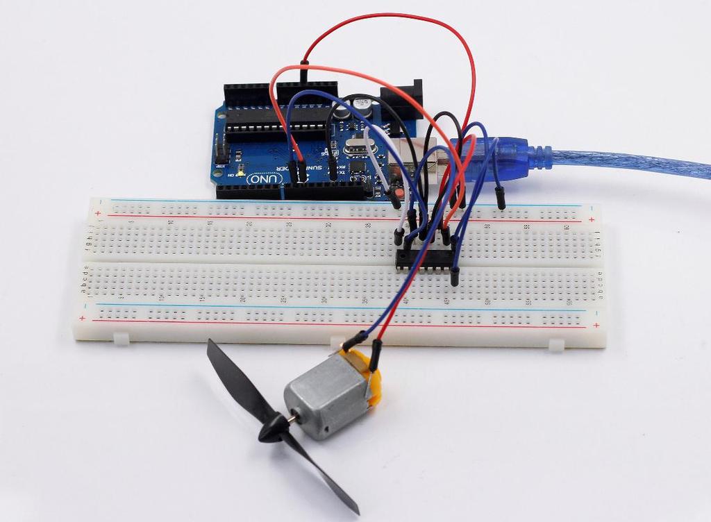
79 Lesson 19 Simple Creation - Small Fan Introduction In this experiment, we will use a button and a DC motor together to assemble a small fan. With the button, we can shift the rotational speed or gear selection of the fan. Components - 1 * SunFounder Uno board - 1 * Breadboard - 1 * USB cable - 1 * DC motor - 1 * Resistor (10KΩ) - 1 * Button - 1 * Motor drive L293D - 1 * 104 Ceramic Capacitor - 1 * Fan - Jumper wires Principle This experiment is to control the rotational speed of the motor by reading the times the button is pressed. The chip L293D for motor drive, many details have been provide in Lesson 7. You may check the principle if necessary. The capacitor and resistor here connected to the button in parallel is to eliminate jitters and output a steady low level, so as to protect the motor. The fan has 4 gears. After startup, the default gear is 0 and the fan will not rotate. If the button is pressed once, the small fan will get into first gear (low speed) and rotate slowly; for pressing twice, it will get into the second gear (medium speed) and rotate at a medium pace; for pressing three times, it will get into third gear (high speed) and rotate rapidly. If the button is pressed four times, it will return to 0 gear and stop. Experimental Procedures Step 1: Build the circuit 76


80 The schematic diagram 77

81 Step 2: Program (Please refer to the example code in LEARN -> Get Tutorials on our website) Step 3: Compile the code Step 4: Upload the sketch to the SunFounder Uno board As mentioned above, the times you press the button will change the rotational speed of the fan. Pressing it once will cause it to rotate slowly, while three times will cause it to rotate rather quickly, and pressing it four times will cause it to stop. 78
82 Copyright Notice All contents including but not limited to texts, images, and code in this manual are owned by the SunFounder Company. You should only use it for personal study, investigation, enjoyment, or other non-commercial or nonprofit purposes, under the related regulations and copyrights laws, without infringing the legal rights of the author and relevant right holders. For any individual or organization that uses these for commercial profit without permission, the Company reserves the right to take legal action. 79
Preface. If you have any TECHNICAL questions, add a topic under FORUM section on our website and we'll reply as soon as possible.
 About SunFounder Preface SunFounder is a technology company focused on Raspberry Pi and Arduino open source community development. Committed to the promotion of open source culture, we strive to bring
This module senses temperature and humidity. Output: Temperature and humidity display on serial monitor.
 Elegoo 37 Sensor Kit v2.0 Elegoo provides tutorials for each of the sensors in the kit provided by Maryland MESA. Each tutorial focuses on a single sensor and includes basic information about the sensor,
MAKEVMP502 BASIC LEARNING KIT FOR RASPBERRY PI USER MANUAL
 BASIC LEARNING KIT FOR RASPBERRY PI USER MANUAL USER MANUAL 1. Introduction To all residents of the European Union Important environmental information about this product This symbol on the device or the
16 Stage Bi-Directional LED Sequencer
 16 Stage Bi-Directional LED Sequencer The bi-directional sequencer uses a 4 bit binary up/down counter (CD4516) and two "1 of 8 line decoders" (74HC138 or 74HCT138) to generate the popular "Night Rider"
Experiment 0: Hello, micro:bit!
 Experiment 0: Hello, micro:bit! Introduction Hello World is the term we use to define that first program you write in a programming language or on a new piece of hardware. Essentially it is a simple piece
CATHODE RAY OSCILLOSCOPE. Basic block diagrams Principle of operation Measurement of voltage, current and frequency
 CATHODE RAY OSCILLOSCOPE Basic block diagrams Principle of operation Measurement of voltage, current and frequency 103 INTRODUCTION: The cathode-ray oscilloscope (CRO) is a multipurpose display instrument
Bill of Materials: Super Simple Water Level Control PART NO
 Super Simple Water Level Control PART NO. 2169109 Design a simple water controller in which electrodes are required to sense high and low water levels in a tank. Whenever the water level falls below the
Part No. ENC-LAB01 Users Manual Introduction EncoderLAB
 PCA Incremental Encoder Laboratory For Testing and Simulating Incremental Encoder signals Part No. ENC-LAB01 Users Manual The Encoder Laboratory combines into the one housing and updates two separate encoder
Alice EduPad Board. User s Guide Version /11/2017
 Alice EduPad Board User s Guide Version 1.02 08/11/2017 1 Table OF Contents Chapter 1. Overview... 3 1.1 Welcome... 3 1.2 Launchpad features... 4 1.3 Alice EduPad hardware features... 4 Chapter 2. Software
8 PIN PIC PROGRAMMABLE BOARD (DEVELOPMENT BOARD & PROJECT BOARD)
") ESSENTIAL INFORMATION BUILD INSTRUCTIONS CHECKING YOUR PCB & FAULT-FINDING MECHANICAL DETAILS HOW THE KIT WORKS LEARN ABOUT PROGRAMMING WITH THIS 8 PIN PIC PROGRAMMABLE BOARD (DEVELOPMENT BOARD & PROJECT
ESSENTIAL INFORMATION BUILD INSTRUCTIONS CHECKING YOUR PCB & FAULT-FINDING MECHANICAL DETAILS HOW THE KIT WORKS LEARN ABOUT PROGRAMMING WITH THIS 8 PIN PIC PROGRAMMABLE BOARD (DEVELOPMENT BOARD & PROJECT
ECE 372 Microcontroller Design
 E.g. Port A, Port B Used to interface with many devices Switches LEDs LCD Keypads Relays Stepper Motors Interface with digital IO requires us to connect the devices correctly and write code to interface
Measure the value of water flow using water flow sensor and DC water pump 12 V interfacing with Arduino uno
 1 2 Measure the value of water flow using water flow sensor and DC water pump 12 V interfacing with Arduino uno A flow sensor is a device for sensing the rate of fluid flow. Typically a flow sensor is
QUIZ BUZZER KIT TEACHING RESOURCES. Version 2.0 WHO ANSWERED FIRST? FIND OUT WITH THIS
 TEACHING RESOURCES SCHEMES OF WORK DEVELOPING A SPECIFICATION COMPONENT FACTSHEETS HOW TO SOLDER GUIDE WHO ANSWERED FIRST? FIND OUT WITH THIS QUIZ BUZZER KIT Version 2.0 Index of Sheets TEACHING RESOURCES
1.5mm amplitude at 10 to 55Hz frequency in each X, Y, Z direction for 2 hours 500m/s² (approx. 50G) in each X, Y, Z direction for 3 times
 in each X, Y, Z direction for 3 times") Color Mark Color Mark Feature Outstanding color matching accuracy - RGB light emitting diodes and 12-bit resolution - 2 detection modes (color only / color + intensity) - -step sensitivity adjustment for
Color Mark Color Mark Feature Outstanding color matching accuracy - RGB light emitting diodes and 12-bit resolution - 2 detection modes (color only / color + intensity) - -step sensitivity adjustment for
UNIT V 8051 Microcontroller based Systems Design
 UNIT V 8051 Microcontroller based Systems Design INTERFACING TO ALPHANUMERIC DISPLAYS Many microprocessor-controlled instruments and machines need to display letters of the alphabet and numbers. Light
COLOUR CHANGING USB LAMP KIT
 TEACHING RESOURCES SCHEMES OF WORK DEVELOPING A SPECIFICATION COMPONENT FACTSHEETS HOW TO SOLDER GUIDE SEE AMAZING LIGHTING EFFECTS WITH THIS COLOUR CHANGING USB LAMP KIT Version 2.1 Index of Sheets TEACHING
The Micropython Microcontroller
 Please do not remove this manual from the lab. It is available via Canvas Electronics Aims of this experiment Explore the capabilities of a modern microcontroller and some peripheral devices. Understand
Overview of All Pixel Circuits for Active Matrix Organic Light Emitting Diode (AMOLED)
") Chapter 2 Overview of All Pixel Circuits for Active Matrix Organic Light Emitting Diode (AMOLED) ---------------------------------------------------------------------------------------------------------------
Chapter 2 Overview of All Pixel Circuits for Active Matrix Organic Light Emitting Diode (AMOLED) ---------------------------------------------------------------------------------------------------------------
Chapter 9 MSI Logic Circuits
 Chapter 9 MSI Logic Circuits Chapter 9 Objectives Selected areas covered in this chapter: Analyzing/using decoders & encoders in circuits. Advantages and disadvantages of LEDs and LCDs. Observation/analysis
Data Sheet. Electronic displays
 Data Pack F Issued November 0 029629 Data Sheet Electronic displays Three types of display are available; each has differences as far as the display appearance, operation and electrical characteristics
SignalTap Plus System Analyzer
 SignalTap Plus System Analyzer June 2000, ver. 1 Data Sheet Features Simultaneous internal programmable logic device (PLD) and external (board-level) logic analysis 32-channel external logic analyzer 166
L, LTC, LTM, LT are registered trademarks of Linear Technology Corporation. Other product
 DESCRIPTION WARNING! Do not look directly at operating LED. This circuit produces light that can damage eyes. Demo Circuit 1265 QUICK START GUIDE LTC3220/LTC3220-1 360mA Universal 18-Channel LED Driver
Data Acquisition Using LabVIEW
 Experiment-0 Data Acquisition Using LabVIEW Introduction The objectives of this experiment are to become acquainted with using computer-conrolled instrumentation for data acquisition. LabVIEW, a program
Laboratory 8. Digital Circuits - Counter and LED Display
 Laboratory 8 Digital Circuits - Counter and Display Required Components: 2 1k resistors 1 10M resistor 3 0.1 F capacitor 1 555 timer 1 7490 decade counter 1 7447 BCD to decoder 1 MAN 6910 or LTD-482EC
Revision 1.2d
 Specifications subject to change without notice 0 of 16 Universal Encoder Checker Universal Encoder Checker...1 Description...2 Components...2 Encoder Checker and Adapter Connections...2 Warning: High
4.9 BEAM BLANKING AND PULSING OPTIONS
 4.9 BEAM BLANKING AND PULSING OPTIONS Beam Blanker BNC DESCRIPTION OF BLANKER CONTROLS Beam Blanker assembly Electron Gun Controls Blanker BNC: An input BNC on one of the 1⅓ CF flanges on the Flange Multiplexer
Laboratory 11. Required Components: Objectives. Introduction. Digital Displays and Logic (modified from lab text by Alciatore)
") Laboratory 11 Digital Displays and Logic (modified from lab text by Alciatore) Required Components: 2x lk resistors 1x 10M resistor 3x 0.1 F capacitor 1x 555 timer 1x 7490 decade counter 1x 7447 BCD to
Laboratory 11 Digital Displays and Logic (modified from lab text by Alciatore) Required Components: 2x lk resistors 1x 10M resistor 3x 0.1 F capacitor 1x 555 timer 1x 7490 decade counter 1x 7447 BCD to
Logic Gates, Timers, Flip-Flops & Counters. Subhasish Chandra Assistant Professor Department of Physics Institute of Forensic Science, Nagpur
 Logic Gates, Timers, Flip-Flops & Counters Subhasish Chandra Assistant Professor Department of Physics Institute of Forensic Science, Nagpur Logic Gates Transistor NOT Gate Let I C be the collector current.
TV Character Generator
 TV Character Generator TV CHARACTER GENERATOR There are many ways to show the results of a microcontroller process in a visual manner, ranging from very simple and cheap, such as lighting an LED, to much
V6118 EM MICROELECTRONIC - MARIN SA. 2, 4 and 8 Mutiplex LCD Driver
 EM MICROELECTRONIC - MARIN SA 2, 4 and 8 Mutiplex LCD Driver Description The is a universal low multiplex LCD driver. The version 2 drives two ways multiplex (two blackplanes) LCD, the version 4, four
Dynamic Animation Cube Group 1 Joseph Clark Michael Alberts Isaiah Walker Arnold Li
 Dynamic Animation Cube Group 1 Joseph Clark Michael Alberts Isaiah Walker Arnold Li Sponsored by: Department of Electrical Engineering & Computer Science at UCF What is the DAC? The DAC is an array of
Prototyping & Engineering Electronics Kits Magic Mandala Kit Guide
 Prototyping & Engineering Electronics Kits Magic Mandala Kit Guide odysseyboard.com Please refer to www.odysseyboard.com for a PDF updated version of this guide. Magic Mandala Guide version 1.0, February,
Arduino Lesson 3. RGB LEDs
 Arduino Lesson 3. RGB LEDs Created by Simon Monk Last updated on 2013-06-22 06:45:59 PM EDT Guide Contents Guide Contents Overview Parts Part Qty Breadboard Layout Colors Arduino Sketch Using Internet
0.56" 4 Digital Blue LED Panel Meter (rescalable) User s Guide
 User s Guide") 0.56" 4 Digital Blue LED Panel Meter (rescalable) User s Guide 2004-2009 Sure Electronics Inc. ME-SP037B_Ver1.0 0.56" 4 DIGITAL BLUE LED PANEL METER (RESCALABLE) USER S GUIDE Table of Contents Chapter
0.56" 4 Digital Blue LED Panel Meter (rescalable) User s Guide 2004-2009 Sure Electronics Inc. ME-SP037B_Ver1.0 0.56" 4 DIGITAL BLUE LED PANEL METER (RESCALABLE) USER S GUIDE Table of Contents Chapter
ELECTRONIC GAME KIT TEACHING RESOURCES. Version 2.0 BUILD YOUR OWN MEMORY & REACTIONS
 TEACHING RESOURCES SCHEMES OF WORK DEVELOPING A SPECIFICATION COMPONENT FACTSHEETS HOW TO SOLDER GUIDE BUILD YOUR OWN MEMORY & REACTIONS ELECTRONIC GAME KIT Version 2.0 Index of Sheets TEACHING RESOURCES
Transducers and Sensors
 Transducers and Sensors Dr. Ibrahim Al-Naimi Chapter THREE Transducers and Sensors 1 Digital transducers are defined as transducers with a digital output. Transducers available at large are primary analogue
PHYS 3322 Modern Laboratory Methods I Digital Devices
 PHYS 3322 Modern Laboratory Methods I Digital Devices Purpose This experiment will introduce you to the basic operating principles of digital electronic devices. Background These circuits are called digital
Lesson 4 RGB LED. Overview. Component Required:
 Lesson 4 RGB LED Overview RGB LEDs are a fun and easy way to add some color to your projects. Since they are like 3 regular LEDs in one, how to use and connect them is not much different. They come mostly
Smart Interface Components. Sketching in Hardware 2 24 June 2007 Tod E. Kurt
 Smart Interface Components Sketching in Hardware 2 24 June 2007 Tod E. Kurt Interface Components? Sensors buttons / knobs light sound Actuators motion / vibration lights sound force proximity, location
STX Stairs lighting controller.
 Stairs lighting controller STX-1795 The STX-1795 controller serves for a dynamic control of the lighting of stairs. The lighting is switched on for consecutive steps, upwards or downwards, depending on
7 SEGMENT LED DISPLAY KIT
 ESSENTIAL INFORMATION BUILD INSTRUCTIONS CHECKING YOUR PCB & FAULT-FINDING MECHANICAL DETAILS HOW THE KIT WORKS CREATE YOUR OWN SCORE BOARD WITH THIS 7 SEGMENT LED DISPLAY KIT Version 2.0 Which pages of
MODULAR DIGITAL ELECTRONICS TRAINING SYSTEM
 MODULAR DIGITAL ELECTRONICS TRAINING SYSTEM MDETS UCTECH's Modular Digital Electronics Training System is a modular course covering the fundamentals, concepts, theory and applications of digital electronics.
SXGA096 DESIGN REFERENCE BOARD
 SXGA096 DESIGN REFERENCE BOARD For Use with all emagin SXGA096 OLED Microdisplays USER S MANUAL VERSION 1.0 TABLE OF CONTENTS D01-501152-01 SXGA096 Design Reference Board User s Manual i 1. INTRODUCTION...
University of Illinois at Urbana-Champaign
 University of Illinois at Urbana-Champaign Digital Electronics Laboratory Physics Department Physics 40 Laboratory Experiment 3: CMOS Digital Logic. Introduction The purpose of this lab is to continue
Module 4: Traffic Signal Design Lesson 1: Traffic Signal (Arduino) Control System Laboratory Exercise Grade 6-8
 Control System Laboratory Exercise Grade 6-8") Name: Class: Module 4: Traffic Signal Design Lesson 1: Traffic Signal (Arduino) Control System Laboratory Exercise Grade 6-8 Background Traffic signals are used to control traffic that flows in opposing
Name: Class: Module 4: Traffic Signal Design Lesson 1: Traffic Signal (Arduino) Control System Laboratory Exercise Grade 6-8 Background Traffic signals are used to control traffic that flows in opposing
N3ZI Digital Dial Manual For kit with Serial LCD Rev 3.04 Aug 2012
 N3ZI Digital Dial Manual For kit with Serial LCD Rev 3.04 Aug 2012 Kit properly assembled and configured for Standard Serial LCD (LCD Not yet connected) Kit Components Item Qty Designator Part Color/Marking
TIL311 HEXADECIMAL DISPLAY WITH LOGIC
 TIL311 Internal TTL MSI IC with Latch, Decoder, and Driver 0.300-Inch (7,62-mm) Character Height Wide Viewing Angle High Brightness Left-and-Right-Hand Decimals Constant-Current Drive for Hexadecimal Characters
PESIT Bangalore South Campus
 SOLUTIONS TO INTERNAL ASSESSMENT TEST 3 Date : 8/11/2016 Max Marks: 40 Subject & Code : Analog and Digital Electronics (15CS32) Section: III A and B Name of faculty: Deepti.C Time : 11:30 am-1:00 pm Note:
QTI Line Follower AppKit for the Boe-Bot (#28108)
") Web Site: www.parallax.com Forums: forums.parallax.com Sales: sales@parallax.com Technical: support@parallax.com Office: (916) 624-8333 Fax: (916) 624-8003 Sales: (888) 512-1024 Tech Support: (888) 997-8267
Web Site: www.parallax.com Forums: forums.parallax.com Sales: sales@parallax.com Technical: support@parallax.com Office: (916) 624-8333 Fax: (916) 624-8003 Sales: (888) 512-1024 Tech Support: (888) 997-8267
Combo Board.
 Combo Board www.matrixtsl.com EB083 Contents About This Document 2 General Information 3 Board Layout 4 Testing This Product 5 Circuit Diagram 6 Liquid Crystal Display 7 Sensors 9 Circuit Diagram 10 About
MBI5152 Application Note
 MBI552 Application Note Forward MBI552 features an embedded 8k-bit SRAM, which can support up to :6 time-multiplexing application. Users only need to send the whole frame data once and to store in the
PHYSICS 5620 LAB 9 Basic Digital Circuits and Flip-Flops
 PHYSICS 5620 LAB 9 Basic Digital Circuits and Flip-Flops Objective Construct a two-bit binary decoder. Study multiplexers (MUX) and demultiplexers (DEMUX). Construct an RS flip-flop from discrete gates.
EXPERIMENT #6 DIGITAL BASICS
 EXPERIMENT #6 DIGITL SICS Digital electronics is based on the binary number system. Instead of having signals which can vary continuously as in analog circuits, digital signals are characterized by only
QUICK START GUIDE FOR DEMONSTRATION CIRCUIT /12/14 BIT 10 TO 105 MSPS ADC
 LTC2280, LTC2282, LTC2284, LTC2286, LTC2287, LTC2288 LTC2289, LTC2290, LTC2291, LTC2292, LTC2293, LTC2294, LTC2295, LTC2296, LTC2297, LTC2298 or LTC2299 DESCRIPTION Demonstration circuit 851 supports a
ELECTRICAL ENGINEERING DEPARTMENT California Polytechnic State University
 EECTRICA ENGINEERING DEPARTMENT California Polytechnic State University EE 361 NAND ogic Gate, RS Flip-Flop & JK Flip-Flop Pre-lab 7 1. Draw the logic symbol and construct the truth table for a NAND gate.
Assembly and Operating Instructions for HiViz.com Kits
 information and inspiration for students, teachers and hobbyists About Tools Products Activities Galleries Projects FAQ Links Contact Assembly and Operating Instructions for HiViz.com Kits For best results
EE 367 Lab Part 1: Sequential Logic
 EE367: Introduction to Microprocessors Section 1.0 EE 367 Lab Part 1: Sequential Logic Contents 1 Preface 1 1.1 Things you need to do before arriving in the Laboratory............... 2 1.2 Summary of material
Slot-type Photomicrosensor with connector or pre-wired models (Non-modulated) *1. configuration. Dark-ON/Light-ON
 *1. configuration. Dark-ON/Light-ON") Slot-type Photomicrosensor with connector or pre-wired models (Non-modulated) * EE-SX/6 Photomicrosensor with 0- to 00-mA direct switching capacity for built-in application. Series includes models that
Slot-type Photomicrosensor with connector or pre-wired models (Non-modulated) * EE-SX/6 Photomicrosensor with 0- to 00-mA direct switching capacity for built-in application. Series includes models that
ET-REMOTE DISTANCE. Manual of ET-REMOTE DISTANCE
 ET-REMOTE DISTANCE ET-REMOTE DISTANCE is Distance Measurement Module by Ultrasonic Waves; it consists of 2 important parts. Firstly, it is the part of Board Ultrasonic (HC-SR04) that includes sender and
 Chapter 3 Evaluated Results of Conventional Pixel Circuit, Other Compensation Circuits and Proposed Pixel Circuits for Active Matrix Organic Light Emitting Diodes (AMOLEDs) -------------------------------------------------------------------------------------------------------
MAKE AN RGB CONTROL KNOB.
 MAKE AN RGB CONTROL KNOB. This is a knob based colour changing controller that uses a custom programmed microcontroller to pack a lot of features into a small affordable kit. The module can drive up to
Australian Technical Production Services
 Australian Technical Production Services Dual Rail Crowbar Copyright notice. These notes, the design, schematics and diagrams are Copyright Richard Freeman, 2015 While I am happy for the notes to be printed
MSCI 222C Class Readings Schedule. MSCI 222C - Electronics 11/20/ Class Seating Chart Mondays Class Seating Chart Tuesdays
 222-01 Class Seating Chart Mondays Electronics Door MSCI 222C Fall 2018 Introduction to Electronics Charles Rubenstein, Ph. D. Professor of Engineering & Information Science Session 12: Mon/Tues 11/26/18
Analog Circuits Prof. Nagendra Krishnapura Department of Electrical Engineering Indian Institute of Technology, Madras. Module - 04 Lecture 12
 Analog Circuits Prof. Nagendra Krishnapura Department of Electrical Engineering Indian Institute of Technology, Madras Module - 04 Lecture 12 So, far we have discussed common source amplifier using an
Azatrax Model Railroad Track Signal Control - Single Track
 Installation Guide Azatrax Model Railroad Track Signal Control - Single Track TS2 What it is: The TS2 operates one or two trackside block signals (one in each direction) on one track to simulate the block
Microcontrollers and Interfacing week 7 exercises
 SERIL TO PRLLEL CONVERSION Serial to parallel conversion Microcontrollers and Interfacing week exercises Using many LEs (e.g., several seven-segment displays or bar graphs) is difficult, because only a
Build A Video Switcher
 Build A Video Switcher VIDEOSISTEMAS serviciotecnico@videosistemas.com www.videosistemas.com Reprinted with permission from Electronics Now Magazine September 1997 issue Copyright Gernsback Publications,
ECB DIGITAL ELECTRONICS PROJECT BASED LEARNING PROJECT REPORT ON 7 SEGMENT DIGITAL STOP WATCH USING DECODER
 ECB2212 - DIGITAL ELECTRONICS PROJECT BASED LEARNING PROJECT REPORT ON 7 SEGMENT DIGITAL STOP WATCH USING DECODER SUBMITTED BY ASHRAF HUSSAIN (160051601105) S SAMIULLAH (160051601059) CONTENTS >AIM >INTRODUCTION
7 SegmneDisplay Unit With High Bright Characters (D1SC-N : W32 H57mm, D1SA Series: W11 H22mm)
") SC-N/SA Series 7 Segment Display Unit 7 SegmneDisplay Unit With High Bright Characters (SC-N : W32 H57mm, SA Series: W H22mm) Features Selectable decimal (0 to 9) or hexadecimal (0 to 9, A to F) indication
SC-N/SA Series 7 Segment Display Unit 7 SegmneDisplay Unit With High Bright Characters (SC-N : W32 H57mm, SA Series: W H22mm) Features Selectable decimal (0 to 9) or hexadecimal (0 to 9, A to F) indication
Introduction 1. Green status LED, controlled by output signal ST. Sounder, controlled by output signal Q6. Push switch on input D6
 Introduction 1 Welcome to the GENIE microcontroller system! The activity kit allows you to experiment with a wide variety of inputs and outputs... so why not try reading sensors, controlling lights or
NT Output LCD Segment/Common Driver NT7701. Features. General Description. Pin Configuration 1 V1.0
 160 Output LCD Segment/Common Driver Features (Segment mode)! Shift Clock frequency : 14 MHz (Max.) (VDD = 5V ± 10%) 8 MHz (Max.) (VDD = 2.5V - 4.5V)! Adopts a data bus system! 4-bit/8-bit parallel input
QUICK START GUIDE FOR DEMONSTRATION CIRCUIT /12/14 BIT 10 TO 65 MSPS DUAL ADC
 LTC2286, LTC2287, LTC2288, LTC2290, LTC2291, LTC2292, LTC2293, LTC2294, LTC2295, LTC2296, LTC2297, LTC2298 or LTC2299 DESCRIPTION Demonstration circuit 816 supports a family of s. Each assembly features
DEM B SBH-PW-N (A-TOUCH)
") DISPLAY Elektronik GmbH LCD MODULE DEM 128128B SBH-PW-N (A-TOUCH) Version :2 28/Dec/2007 GENERAL SPECIFICATION MODULE NO. : DEM 128128B SBH-PW-N (A-TOUCH) CUSTOMER P/N VERSION NO. CHANGE DESCRIPTION DATE
DISPLAY Elektronik GmbH LCD MODULE DEM 128128B SBH-PW-N (A-TOUCH) Version :2 28/Dec/2007 GENERAL SPECIFICATION MODULE NO. : DEM 128128B SBH-PW-N (A-TOUCH) CUSTOMER P/N VERSION NO. CHANGE DESCRIPTION DATE
Published in A R DIGITECH
 Design of propeller clock by using 8051 Microcontroller Ahmed H. Al-Saadi*1 *1 (B.Sc. of Computer Engineering in Al Hussein University College of Engineering, Iraq) ah9@outlook.com*1 Abstract The propeller
Solid-State Digital Timer
 Solid-State Digital Timer 1/16 DIN, Digital-Set Timer with 0.1 Second to 9,990 Hours Range 8 field-selectable operation modes Universal AC/DC supply voltage timers available Operations include ON-delay,
Operating instructions Electronic preset counter Type series 717
 Operating instructions Electronic preset counter Type series 717 1. Description 5.98.3_gb 6-digit adding/subtracting counter with two presets Very bright 8mm high LED display Counting and preset range
Vorne Industries. 87/719 Analog Input Module User's Manual Industrial Drive Itasca, IL (630) Telefax (630)
 Telefax (630)") Vorne Industries 87/719 Analog Input Module User's Manual 1445 Industrial Drive Itasca, IL 60143-1849 (630) 875-3600 Telefax (630) 875-3609 . 3 Chapter 1 Introduction... 1.1 Accessing Wiring Connections
Vorne Industries 87/719 Analog Input Module User's Manual 1445 Industrial Drive Itasca, IL 60143-1849 (630) 875-3600 Telefax (630) 875-3609 . 3 Chapter 1 Introduction... 1.1 Accessing Wiring Connections
Digital 1 Final Project Sequential Digital System - Slot Machine
 Digital 1 Final Project Sequential Digital System - Slot Machine Joseph Messner Thomas Soistmann Alexander Dillman I. Introduction The purpose of this lab is to create a circuit that would represent the
DIY KIT MHZ 8-DIGIT FREQUENCY METER
 This kit is a stand-alone frequency meter capable of measuring repetitive signals up to a frequency of 50MHz. It has two frequency ranges (15 and 50 MHz) as well as two sampling rates (0.1 and 1 second).
Color Organ Triple Deluxe II.
 http://wwwinstructablescom/id/color-organ-triple-deluxe-ii/ Food Living Outside Play Technology Workshop Color Organ Triple Deluxe II by ledartist on January 13, 2013 Table of Contents Color Organ Triple
Laboratory 9 Digital Circuits: Flip Flops, One-Shot, Shift Register, Ripple Counter
 page 1 of 5 Digital Circuits: Flip Flops, One-Shot, Shift Register, Ripple Counter Introduction In this lab, you will learn about the behavior of the D flip-flop, by employing it in 3 classic circuits:
LCD MODULE DEM B SYH-PY
 DISPLAY ELEKTRONIK GMBH LCD MODULE DEM 128064B SYH-PY Product specification 24/03/2006 GENERAL SPECIFICATION MODULE NO. : DEM 128064B SYH-PY CUSTOMER P/N VERSION NO. CHANGE DESCRIPTION DATE 0 ORIGINAL
USER'S MANUAL. Getting started with ALEXAN ATMEL AT89C2051/AT89C4051 Training Module - 1
 USER'S MANUAL Getting started with ALEXAN ATMEL AT89C05/AT89C405 Training Module - Version.0 Copyright 006 Ace Electronic Technology Inc. All Rights Reserved Alexan 05/405 TM- v..0 Page of 7 About This
BLINKIN LED DRIVER USER'S MANUAL. REV UM-0 Copyright 2018 REV Robotics, LLC 1
 fg BLINKIN LED DRIVER USER'S MANUAL REV-11-1105-UM-0 Copyright 2018 REV Robotics, LLC 1 TABLE OF CONTENTS 1 OVERVIEW... 3 1.1 CONNECTIONS... 3 1.2 KIT CONTENTS... 3 1.3 ELECTRICAL RATINGS... 3 1.4 SUPPORTED
Session 1 Introduction to Data Acquisition and Real-Time Control
 EE-371 CONTROL SYSTEMS LABORATORY Session 1 Introduction to Data Acquisition and Real-Time Control Purpose The objectives of this session are To gain familiarity with the MultiQ3 board and WinCon software.
DAGON Company Leszno Jackowskiego 24 Street tel DAGON Lighting series SPL-3
 DAGON Company 64-100 Leszno Jackowskiego 24 Street tel. +48 664-092-493 dagon@iadagon.pl www.dagonlighting.com DAGON Lighting series SPL-3 DIODES and RGB LED STRIP DRIVER works alone or controlled by:
INPUT OUTPUT GAIN DELAY. Hue Candela Strobe Controller. Hue Candela s STROBE CONTROLLER. Front Panel Actual Size 7 ¼ By 4 ¾ POWER. msec SEC 10 1.
 Hue Candela s STROBE CONTROLLER INPUT OUTPUT ON TIME POWER NO B C A GAIN X LOCK Y OUT Z Hue Candela Strobe Controller 4 5 6 7..... 8. 3. 9. 2 10.. 1 11. STEP m.. 0 10 1. 10 10 1.0 10 zero DELAY. 03. 02.
LINK-RAY TM MODULATORS FOR CONSTANT- VOLTAGE. LinkRay Modulators 12 V / 24 V Constant-voltage Applications MODULATORS
 MUSIUM RESTAURANT SOUVENIR SHOP EXIT LinkRay Modulators 12 V / 24 V Constant-voltage Applications LINK-RAY TM MODULATORS FOR CONSTANT- VOLTAGE LINK-RAY TM MODULATORS FOR CONSTANT-VOLTAGE APPLICATIONS 186755
Electrical connection
 Splice sensor Dimensioned drawing en 04-2014/06 50116166-01 4mm 12-30 V DC We reserve the right to make changes DS_IGSU14CSD_en_50116166_01.fm Reliable detection of splice on paper web or plastic web With
Light Emitting Diodes (LEDs)
") Light Emitting Diodes (LEDs) Example: Circuit symbol: Function LEDs emit light when an electric current passes through them. Connecting and soldering LEDs must be connected the correct way round, the diagram
Light Emitting Diodes (LEDs) Example: Circuit symbol: Function LEDs emit light when an electric current passes through them. Connecting and soldering LEDs must be connected the correct way round, the diagram
N3ZI Digital Dial Manual For kit with Backlit LCD Rev 4.00 Jan 2013 PCB
 N3ZI Digital Dial Manual For kit with Backlit LCD Rev 4.00 Jan 2013 PCB Kit Components Item Qty Designator Part Color/Marking PCB 1 LCD Display 1 LCD 1602 Volt Regulator 1 U1 78L05, Black TO-92 Prescaler
DEM A SBH-PW-N
 DISPLAY Elektronik GmbH CONTENTS LCD MODULE DEM 160160A SBH-PW-N Version : 4.1 29.01.2008 GENERAL SPECIFICATION MODULE NO. : DEM 160160A SBH-PW-N CUSTOMER P/N VERSION NO. CHANGE DESCRIPTION DATE 0 ORIGINAL
Programmable Micro Remote LED Controller for RGB LED Strips - 12 or 24 VDC Part number: PMRC
 11235 West Bernardo Court, Suite 102 San Diego, CA 92127 888-880-1880 Fax: 707-281-0567 EnvironmentalLights.com Programmable Micro Remote LED Controller for RGB LED Strips - 12 or 24 VDC Part number: PMRC
AMP DISPLAY INC. SPECIFICATIONS AMP DISPLAY INC 9856 SIXTH STREET RANCHO CUCAMONGA CA TEL: FAX:
 AMP DISPLA INC. SPECIFICATIONS CUSTOMER CUSTOMER PART NO. AMP PART NO. APPROVED B DATE Approved For Specifications Approved For Specifications & Sample AMP DISPLA INC 9856 SITH STREET RANCHO CUCAMONGA
Building the ChronoDot Calendar Reminder
 Building the ChronoDot Calendar Reminder Being very forgetful and married is not a good combination. Luckily my wife comes up with solutions and suggested that we make some sort of reminder that would
SHENZHEN H&Y TECHNOLOGY CO., LTD
 Chapter I Model801, Model802 Functions and Features 1. Completely Compatible with the Seventh Generation Control System The eighth generation is developed based on the seventh. Compared with the seventh,
EEM Digital Systems II
 ANADOLU UNIVERSITY DEPARTMENT OF ELECTRICAL AND ELECTRONICS ENGINEERING EEM 334 - Digital Systems II LAB 3 FPGA HARDWARE IMPLEMENTATION Purpose In the first experiment, four bit adder design was prepared
CATHODE-RAY OSCILLOSCOPE (CRO)
") CATHODE-RAY OSCILLOSCOPE (CRO) I N T R O D U C T I O N : The cathode-ray oscilloscope (CRO) is a multipurpose display instrument used for the observation, measurement, and analysis of waveforms by plotting
CATHODE-RAY OSCILLOSCOPE (CRO) I N T R O D U C T I O N : The cathode-ray oscilloscope (CRO) is a multipurpose display instrument used for the observation, measurement, and analysis of waveforms by plotting
W0EB/W2CTX DSP Audio Filter Operating Manual V1.12
 W0EB/W2CTX DSP Audio Filter Operating Manual V1.12 Manual and photographs Copyright W0EB/W2CTX, March 13, 2019. This document may be freely copied and distributed so long as no changes are made and the
MAX11503 BUFFER. Σ +6dB BUFFER GND *REMOVE AND SHORT FOR DC-COUPLED OPERATION
 19-4031; Rev 0; 2/08 General Description The is a low-power video amplifier with a Y/C summer and chroma mute. The device accepts an S-video or Y/C input and sums the luma (Y) and chroma (C) signals into