Summer / Fall 2004 Downtime AEG Preparation Work
|
|
|
- Joshua Powers
- 5 years ago
- Views:
Transcription
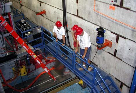
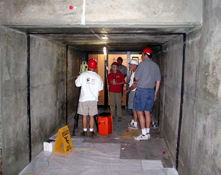
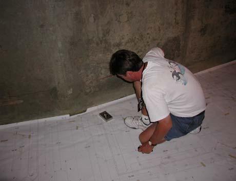
1 Summer / Fall 2004 Downtime AEG Preparation Work In general the Alignment Engineering Group consulted with individuals involved in many of the scheduled downtime activities. Equipment was checked, manpower was increased, and various general preparation tasks were preformed prior to the first day of the down which was Sunday August 1 st, 2004 Babar/IR2 Survey - Instrument calibration (laser tracker, levels, etc.) - Reviewing of 2002 survey data and results Sector 20 LCLS Shielding Wall - Reviewing ROD data gathered June 3 rd, Gathering special alignment scope and targets (Note: the targets fit into bracket holes that are normally diameter. In this particular case it was discovered that the holes were only diameter. Only a few rare targets could be found for this size.)

2 Summer / Fall 2004 Downtime AEG Week 1 Summary BaBar/IR2 survey BaBar IR2 IR2-02 Number of Stations Number of Points Number of Tracker Triplets Number of Height Differences Number of Coordinate Unknowns Number of Nuisance Parameters Number of Datum Parameters Date 8/1/04 8/1-4/ Field Man-Hours

3


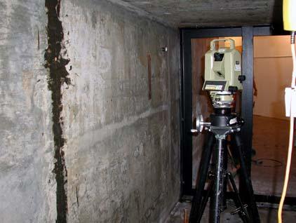
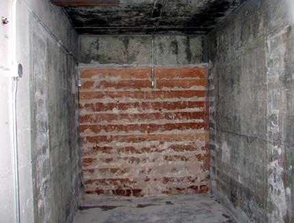
4 Sector 20 LCLS shielding wall - Tuesday August 3 1 TC2002 set-up - Wednesday August 4 8 TC2002 set-ups The wall was down at 12:30PM - Thursday August 5 Levels through floor, wall and jack-points Fit a line through the 7 jack-points: Point X in mil Y in mil Set vacuum pipe with alignment scope - Friday August 6 Compute quad position, assuming that Quad LI is at m: Quad Survey in m Drawing in m LI LI LI The distance from Quad LI to the LCLS injector intersection point is inches per the drawing. Check quad with alignment scope Mark 6 points for the 2 walls construction. The final decision was to have the walls vertical (not perpendicular to the accelerator-injector plane)
5
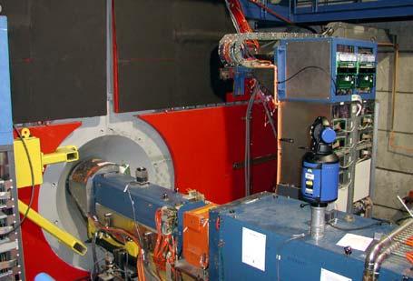
6 PEPII LER SLM - Wednesday August 4 1 crew set 2 out of the 5 stands. Waiting for PPS gate to be opened to lay out stands #2, #4 and #5 SPEAR3 BL0 SLM - Wednesday August 4 Enter drawing values into deck - Thursday August 5 1 crew of 3 used the only 2 available wall monuments to get both X and Y guns. Checked 2 set-ups with SC04SD1, then checked the absorber and set: o Vacuum valve assembly o Drift pipe in permanent magnets o Aperture mask o Cold finger o View port - Friday August 6 1 crew of 3 to set a scribe line in the SLM room (X=0.000, Z= ) Miscellaneous - Monday August 2 through Friday August 6 o Checking and replacing linac laser retractable lens status lights - Thursday August 5 o Fiducialization of horizontal slits for SSRL BL4-2 - Friday August 6 o Fiducialization of horizontal slits for SSRL BL4-2 and BL7-2 o SPEAR3 survey of some wall blocks inside the ring for preparation of 2005 earthquake retrofit

7 Summer / Fall 2004 Downtime AEG Week 2 Summary BaBar Monitoring - Monday August 9 o TC2002 network for baseline survey QU5 QU4 B-side BaBar Detector Survey 8/9/04 The options for the adjustment were to rely on the verticality of the set-ups and to use the coordinates of the wall monuments for the determination of the datum.
8 Number of Stations Number of Points 4 26 Number of TC2002 Triplets Number of Height Differences 56 3 Number of Coordinate Unknowns Number of Nuisance Parameters Number of Datum Parameters Field Man-Hours 25 BaBar Detector Survey Side View
 were established allowing the survey of A, B, C, D, E, F, G, H, I and K.")

9 F E G H D BH2BQU4E BL2BQU4D I QU4 BH2BQU4B BL2BQU4A C QU5 J K B A - Tuesday August 10 o Optical tooling survey for baseline. Two scribe lines (one on each side of the B face) were established allowing the survey of A, B, C, D, E, F, G, H, I and K. The TC2002 survey was re-analyzed to allow direct comparison with the optical tooling solution. A plane representing the face of the detector was made from all the 9 points on the surface. The normal of this plane is called Z axis. Point K was used to set X=0. The average of points B&C and I&J determines Y=0. The comparison between the TC2002 and the optical survey was very good except for point E. Presented on the next page is the histogram of the distribution of all possible X-distances between 2 points on the same side, excluding E:
 - Friday August 13 o First check against baseline (Check #1) after lower blocks removed Since Monday s survey, 2 points disappeared: K and D.")

10 Initial Survey of BaBar B-Side Differences Between Total Station and Optical Tooling Frequency Bin (inches) - Friday August 13 o First check against baseline (Check #1) after lower blocks removed Since Monday s survey, 2 points disappeared: K and D. A replacement of D was installed and a survey made to allow future comparisons. Because of the space created by the lower block removal, the points A and J were opened to leveling observations. Two holes near the bottom points (A and J) were selected and cleaned to accommodate reflector balls. They were measured during this survey and will be used as back-up points in the event of losing more targets. Scribe lines


11 The TC2002 and the level observations were combined in a similar fashion as in the initial survey. In particular, the a-priori standard deviations were identical: 100 µm for distances, 50 µm for height differences, 50 µm over the distance in meters for horizontal angles, 70 µm over the distance in meters for vertical distances. Again the comparison between the total station/level and the optical tooling surveys was very good except for ball E.
12 A 7-parameter transformation on all points was used to compare both Monday s and Friday s survey showing that the detector did not move significantly (from this end) between the 2 surveys. Here are the results: Name DZ (m) DX (m) DY (m) A B C E F G H I J F F WIR BH2BQU4A BH2BQU4B BH2BQU4D BH2BQU4E WIR WIR WIR WIR2A WIR WIR The DZ values report changes in the direction perpendicular to the face of the detector. They are irrelevant for this deformation study and can be explained by the glue creeping into the tooling ball socket and preventing a good repeatability of the placement of the cup holding the reflector ball. The other 2 directions are the ones characteristic of possible deformations. The biggest one for points on the detector is 140 µm. The average for the 9 common points in the X direction is 17 µm with a standard deviation of ±37 µm. It is -42 µm with a standard deviation of ±67 µm for the Y direction. BSY Survey - Monday August 9 o Mapping of 50Q1, 2, 3, and 50B1


13 - Tuesday August 10 o Mapping of 50Q1, 2, 3, and 50B1 - Wednesday August 11 o Mapping and processing of survey data


14 Sector 20 LCLS Shielding Wall - Thursday August 12 o Setting of holes for metal forms on shield wall B (closest to the linac)


15 PEPII Quadrupole & Sextupole Survey - Monday August 9 o Mapping R1 - Tuesday August 10 o Continue mapping region R1


16 - Wednesday August 11 o Continue mapping region R1 - Thursday August 12 o Finish mapping R1 and start R5 Miscellaneous - Monday August 9 o ESA: discussion for setting a scribe line and aligning a future laser o PEPII: walk around ring to plan for sextupole and quadrupole roll survey o Fiducialization of SSRL BL7-2 horizontal slits - Tuesday August 10 o Fiducialization of SSRL BL7-2 horizontal slits o SPEAR3 wall block survey - Wednesday August 11 o Fiducialization for BL9-2 o Set quad LI o SPEAR3 wall block survey o PEPII R6: finished the layout of the stands for the LER SLM o Bld25: check magnetic measurement set-up for NLC permanent magnet - Thursday August 12 o Fiducialization for BL9-2 o Check the fiduacialization of the SPEAR3 SLM mirror M0 after its drop earlier in the week: no change to the original numbers o ESA: scribe-lines - Friday August 13 o PEPII R4: set kicker BL4BHK1
17 Summer / Fall 2004 Downtime AEG Week 3 Summary PEPII Quadrupole & Sextupole Survey - Monday August 16 o Continue mapping R5 - Friday August 20 o Continue mapping R5 o Start mapping R3 Completed Measurements of PEP-II Quadrupoles and Sextupoles August 18, 2004 IR 12 IR 10 IR 2 Aug BaBar N LINAC W E S IR 8 IR 4 IR 6 Complete Click on blue line or IR number for details Alignment Engineering Group Summer 2004 Downtime


18 PEPII HER Injection Line - Monday August 16 o 6 TC2002 set-ups to read components from QM29 to QMR2. Move the bend BLP- and try to move QM31 but had problem with support.
19 - Thursday August 19 o Move QM31 after exchange of rod support Z (in) X (in) Y (in) QM29 HM06QU HM06QU HM06QU QM30 HM07QU HM07QU HM07QU HM07QU QM31 HM07QU HM07QU HM07QU HM07BDAA HM07BDAB HM07BDAC HM07BDAD QM32 HM07QU HM07QU HM07QU HM07BDB HM07BDB HM07BDB HM07BDB HM07BDC HM07BDC HM07BDC HM07BDC HM07BDDA HM07BDDB HM07BDDC HM07BDDD QMR1 HM08QU HM08QU HM08QU HM08QU QMR2 HM08QU HM08QU HM08QU HM08QU

20 PEPII LER R4 kicker - Wednesday August 18 o Set Frascati kicker This longitudinal kicker is actually made of two modules. Each module had been fiducialized individually on the CMM. Then the 2 modules were bolted together. In the field, 2 TBs on one module and 1 on the other were used to set the kicker. Then some other TBs were read. See table below: Z (in) X (in) Y (in) Z (mm) X (mm) Y (mm) BL4BLK BL4BLK BL4BLK BL4BLK BL4BLK1A BL4BLK1B BL4BLK1C BL4BLK1D The yellow lines indicate the 3 TBs that were used for the setting. After discussions with Mohammad Dormiani and David Kharakh, it was decided to roll the second module. Here are the new found values:

21 Z (in) X (in) Y (in) Z (mm) X (mm) Y (mm) BL4BLK BL4BLK BL4BLK BL4BLK BL4BLK1A BL4BLK1B BL4BLK1C BL4BLK1D Again the highlighted boxes reflect the values set in the field. The second module is rolled to the first one by approximately 10 milliradians. - Friday August 20 o Set transverse vertical kicker using flanges and features. SPEAR3 BL6-0 - Monday August 16 o Set the 4-jaw slit tank, the BPM and the tapered mask - Tuesday August 17 o Set the M0 mirror tank and 1 slit on the 4-jaw slit tank


22 - Wednesday August 18 o Set the remaining 3 slits - Thursday August 17 o Set the M0 mirror Linac Laser Alignment System - Monday August 16 o Plug open o Special AEG built indicator box used - Tuesday August 17


23 - Wednesday August 18 o The laser was down because of power outage, so no actual visual check of image quality could be done. The last10 sectors were physically inspected both from the klystron gallery and the accelerator housing; no target was found in. o 20-6 air shut off; 5-9 electricians??? - Friday August 20
24 Miscellaneous - Monday August 16 o SSRL Vacuum: Fiducialization of graphite filters for SSRL BL9-2, BL4-1 and BL4-2 o PEPII: gather CMM data for Frascati kicker set-up o Sector 20 LCLS shielding wall: verify location of holes in shield wall B after setting the wall - Tuesday August 17 o SSRL Vacuum: Fiducialization of graphite filters for SSRL BL4-3, BL7-2. BL7-3, BL9-3 and BL Wednesday August 18 o Check paperwork for all the previous graphite filter fiducialization o SSRL: start layout for stairs foundations outside building Thursday August 19 o Assemble paperwork for all the previous graphite filter fiducialization o SPEAR3 BL0: set mirror M0 in beamline o Sector 20 LCLS shielding wall: check progress o PEPII SLM: review the strongback alignment procedure for the PEPII LER vacuum arc chamber (SA ) o FFTB E166: review the alignment schemes for the Tungsten collimators (PC7 and PC7.8) - Friday August 20 o SSRL Vacuum: design support plate for future assembly o SSRL: finish layout for stairs foundations outside building 130


25 Summer / Fall 2004 Downtime AEG Week 4 Summary BaBar Monitoring - Monday August 23 o This survey is designed to check the detector after the installation of the brass plates in the lower part of the detector. o It is based on the same observation scheme as the one described in week 2. The problems encountered this time: Loss of tooling ball socket J after the 4 TC2002 set-ups and before the optical tooling reading. A new socket, called J2, was installed for future surveys. Its X offset was read and an additional total station set-up was made to determine its position. The tooling ball socket for F1 seems to have some glue in the hole and/or the nearby concrete fillet blocks the cup from sitting down fully: special attention should be made in choosing the appropriate Hubbs cup (it may need a short shank).


26 The TC2002 data adjustment based on the previous coordinates show no significant movements. The 2 sets of optical tooling data match the adjusted X-coordinates. The level data are set apart right now in order to study the nonrepeatability of F1 in the Y direction. PEPII Quadrupole & Sextupole Survey - Monday August 23 o Continue mapping R3 - Tuesday August 24 o Finish mapping R3 and R5 o Start mapping R7 and R11 - Wednesday August 25 o Continue mapping R7 and R11 o Start mapping R9 - Thursday August 26 o Finish mapping R7 o Continue mapping R11 - Friday August 27 o Start mapping R9 & R11
27 Completed Measurements of PEP-II Quadrupoles and Sextupoles August 18, 2004 IR 12 IR 10 Aug 12 BaBar IR 2 LINAC N E W Aug 24 S IR 8 Aug 26 Aug 24 IR 4 IR 6 Complete Click on blue line or IR number for details Alignment Engineering Group Summer 2004 Downtime Sector 20 LCLS Shielding Wall - Monday August 23 o Read the upstream wall A: found that it was placed 7/8 too high and 3/8 too close to the tunnel wall. It was moved and ended still 1/4 too high and 1/4 too close. The bolts have not been tightened yet.


28 - Tuesday August 24 - Thursday August 26 o The following results were sent: Pipe X (in) Y (in) Beam Line Pipe Beam Line Pipe Beam Line Pipe Beam Line Pipe
29 Laser Pipe (East) Laser Pipe (East) Laser Pipe (East) Laser Pipe (East) Laser Pipe (West) Laser Pipe (West) Laser Pipe (West) Laser Pipe (West) These are as-built values with the following convention: the numbering starts from the linac and goes towards the injector room. In other words: 1 is South and 4 is North. o The distance from the linac floor to the klystron gallery floor was measured by a Disto to be meters South Damping Rings Summary of Original Job Request: QD1085 DS10QU7 SLTR QF1085: ready for alignment. On downtime schedule, job #D-MMR-080. All four coils removed, support stand was not adjusted. DS13QU2 SLTR QD 1355: ready for alignment. Not scheduled. All four coils removed, magnet support stand was removed. DS02BD1 SLTR Bend 291 (dipole): Not scheduled. Need to read magnet position and possibly move. Magnet support removed, coils removed. Vacuum chamber has been dimpled. Need alignment to read magnet, once we know how much we need to move magnet, Mechanical Engineer will determine if moving in direction needed would damage vac. chamber further DN07BD5 NRTL Bend 790 (dipole): ready for alignment. Not scheduled. Magnet support stand not adjusted, coils replaced. Very difficult location to access.


")

30 - Friday August 27 o QD1085 This quad was set using optical tooling methods and was left off ideal in X 8 mils US and 12 mils DS, for lack of proper movers. o QD1355 (optical tooling set-up) o Bend 291 (TC2002 set-up) This bend was measured and values were given for future work.


31 o Bend 790 (TC2002 set-up) LER Vacuum Chamber - Friday August 27

32 SPEAR3 BL0 SLM - Monday August 23 o Read the cold finger after the installation of the bellows: found it 150 mils out in X (towards SPEAR). It cannot be moved because of the bellows, so this final position was accepted and recorded. SPEAR3 BL6-2 - Thursday August 26 o Align mono and mirror - Friday August 27 o Align slits and check mirror Linac Laser Alignment System - Monday August 23 o The baffle activation late last Friday did not bring any positive conclusion. With only one key, only one baffle at a time could be activated and the presence of one baffle did not seem to change the image of a target.

33 o 2-9 has its panel missing so it could not be activated and thus prevented any attempt to start a recording, as the reference line is established from the laser position to 2-9 with a check on o The visual inspection of targets failed. It was later found that 2 targets were in after the electrical panel replacement. - Tuesday August 24 o A decision was made and relayed by Tom Graul that all sector 2 panels will not be replaced because of potential electrical hazards. We requested to have the ability to manually activate 2-9 from the klystron gallery. o A first attempt at using the program imdetect showed that: There is a factor 10 between the position recorded in the database and the positions read on the magnescale. There is no easy way to repeat a displacement with the mouse alone. So it seemed difficult to fake the 2-9 position to start a new recording with the automatic image detection and the right relation to 2-9 as it was made in Wednesday August 25 o Tom Graul arranged for the installation of the air solenoid in 2-9: a temporary power cord (see the enhanced picture above) is attached directly to the solenoid and can be plugged into any of the regular electrical outlets on the other side of the panel in order to move the target into the in position. The target was tested and produced the following image in the blue room.


34 - Thursday August 26 - Friday August 27 o Contact Bill Herrmannsfeldt for insight on use of baffles. Miscellaneous - Tuesday August 24 o SSRL Vacuum: install slits into tank for BL6-2 - Wednesday August 25 o SSRL Vacuum: install slits into tank for BL6-2
35 o LCLS Preparation: Generate elevations for floor and ceiling of the PEP tunnel and SLC tunnel at the intersection locations where the LCLS tunnel will pass over them: SLC ceiling 68.7 m, floor 65.5m PEPII ceiling 68.4 m, floor 65.2m The values for the SLC are based on GS52YY1 and checked with the floor rivet: RSFF1371. The values for PEPII are based on BH3AQUQ and checked with the wall monument: 226A. - Thursday August 26 o E166 The collimator PC7.7 was set using both the adjustments at the base of the pedestals and the ones on the top. A new table was set in elevation (pitched to match the γ line) with the constraints of the future lead shielding and the presence of the flanges under the table top. - Friday August 27 o Outside wire set-up testing for LCLS
36 Summer / Fall 2004 Downtime AEG Week 5 Summary PEPII Quadrupole & Sextupole Survey Completed Measurements of PEP-II Quadrupoles and Sextupoles September 3, 2004 IR 12 IR 10 Sept 1 IR 2 Aug 30 Aug N Aug 12 BaBar LINAC Aug 31 W E Aug 24 S IR 8 Aug 26 Aug 24 IR 4 IR 6 Complete Click on blue line or IR number for details Alignment Engineering Group Summer 2004 Downtime - Monday August 30 o Finish R11 o Start and finish R10 - Tuesday August 31 o Finish R9
37 - Wednesday September 1 o R8 is closed for RF testing o Start and finish R12 o Went to pick up the tiltmeter from Applied GeoMechanics in Santa Cruz - Thursday September 2 o R4 o Study the repaired tiltmeter
38 SPEAR3 Alignment - Monday August 30 o Finish level shot on floor points: 89 height differences 46 points surveyed (38 ring floor) Ring Floor Height Changes in meters from November 2003 to August 2004 based on level only Cell East Straight Cell Tuesday August 31 o Start level shots to wall points o Add extension to wall monuments in areas where light fixtures prevent placement of regular tooling. (Note sticky notes added to back of rod to indicate safe zone to read bar code.)
 -")


39 - Wednesday September 1 o 2 crews of leveling (1 Zeiss, 1Leica for the high ceiling area) - Thursday September 2 o 1 leveling crew finished the wall points o Calibration of trackers in Sector10 in preparation of next week mapping - Friday September 3 o Move gear in the tunnel

 o Flap partially")
40 Linac Laser Alignment System - Monday August 30 o Before damage to flap (August 17, 2004) o Flap partially failing


41 o Flap broken - Tuesday August 31 o Show flap problem and wait for repair decision - Friday September 3 o Light pipe vented and flap repair begun Miscellaneous - Tuesday August 31 o SSRL Vacuum: BL9-3 vertical slits o FFTB 166: gather deck data to set vertical bend
42 - Wednesday September 1 o SSRL Vacuum: BL9-3 vertical slits o FFTB 166: set vertical bend and corrector - Thursday September 2 o SSRL Vacuum: BL9-3 vertical slits o FFTB 166 Reset the table to the pitch after the vertical bend [.2727 (linac) (bend angle)] o Set pipe - Friday September 3 o FFTB 166
43 Summer / Fall 2004 Downtime AEG Week 6 Summary PEPII Quadrupole & Sextupole Survey Completed Measurements of PEP-II Quadrupoles and Sextupoles September 3, 2004 IR 12 IR 10 Sept 1 IR 2 Aug 27 Aug 12 BaBar Aug 30 N LINAC Aug 31 W E Aug 24 S Sept 2 IR 8 Aug 26 Aug 24 IR 4 (waiting for access to complete) IR 6 Complete Click on blue line or IR number for details Alignment Engineering Group Summer 2004 Downtime
44 PEP2 High Energy Magnet X Positions (2004) X Position (inches) Quad Sext Other Z Distance (meters) PEP2 Low Energy Magnet X Positions (2004) X Position (inches) Quad Sext Other Z Distance (meters)
45 PEP2 High Energy Magnet Y Positions (2004) Y Position (inches) Quad Sext Other Z Distance (meters) PEP2 Low Energy Magnet Y Positions (2004) Y Position (inches) Quad Sext Other Z Distance (meters) - Wednesday September 8 o Tiltmeter measurements of low energy quadrupoles


46 - Thursday September 9 o Continuing tiltmeter measurements - Friday September 10 o Check quadrupole roll showing major difference since 2000 as well as sextupole position far from neighboring quad. SPEAR3 Alignment - Tuesday September 7 o 2 crews for laser tracker mapping - Wednesday September 8 o 2 crews for laser tracker mapping and 1 crew for leveling through the doors


47 - Thursday September 9 o 2 crews for laser tracker mapping - Friday September 10 o Mapping completed o Review BL11 area


48 Linac Laser Alignment System Flap repair continuing during this week. - Thursday September 9 o flaps were repaired and installed
. Could not adjust one of them in X for lack of a proper mover.")
49 - Friday September 10 o Glass cover replaced Miscellaneous - Tuesday September 7 o SSRL Vacuum: BL9-3 vertical slits - Wednesday September 8 o SPEAR3 Ring: BL9 preparation for Xmas installation - Thursday September 9 o SLTR: Went to check the following 2 magnets (QD1295 and QF1315). Could not adjust one of them in X for lack of a proper mover. Will wait for the insertion of a plate to allow for proper moves. - Friday September 10 o SPEAR3: Survey wall in the East Straight (9S) for future beamline. - Saturday September 11 o LCLS Injector area: as-built survey (map) of wall A and wall B. read fast valve and flanges on accelerator line.
50 Summer / Fall 2004 Downtime AEG Week 7 Summary PEPII Quadrupole & Sextupole Survey Completed Measurements of PEP-II Quadrupoles and Sextupoles September 17, 2004 IR 12 LINAC IR 10 Aug 31 Sept 1 Aug 27 Aug 12 BaBar Aug 30 W Sept 16 N E S Sept 2 Aug 24 IR 2 IR 8 Aug 26 Aug 24 IR 4 IR 6 Complete Click on blue line or IR number for details Alignment Engineering Group Summer 2004 Downtime - Tuesday September 14 o Finish R6 o Start R8 - Wednesday September 15 o Finish R8 o Finish tiltmeter observations

51 - Thursday September 16 o Repeat of some magnets in R8. Only 4 magnets at the end of R6B to record in order to have the full ring. Waiting until the area is less crowded. SPEAR3 Alignment - Monday September 13 o Start processing tracker and leveling data - Tuesday September 14 o Study changes in monument positions since last map as well as magnet center position versus ideals. - Wednesday September 15 o Add 2 tracker stations around the West Straight area. One just in front of BL11 ID (needed to install an orange bracket on the wall and drill holes in the protective cover in order to allow cross shot) - Thursday September 16 o Laser tracker survey using arcing techniques for the matching cells in the East Straight o Decide on a global X move in the West straight area. o Perform the X moves in cell 1 and part of cell 18

52 - Friday September 17 o Move cells 18 and 17 - Saturday September 18 o Continue to move cells Linac Laser Alignment System - Thursday September 16 o Pumping started, need to wait for proper pressure. - Friday September 17 o Still waiting. Miscellaneous - Monday September 13 o SSRL Vacuum: BL4-2 vertical slits o SPEAR3: BL6-2 vertical slits The brass plugs in the hutch were found to be of different dates.


53 o PEPII R4: set the 2 new RF cavities The cavities were set through optical tooling set-ups based on the flanges of the neighboring quads.


54 - Tuesday September 14 o SPEAR3: BL6-2 vertical slits Remark the plug line Align the vertical slits o SPEAR3: BL5 ID repeatability test
 after plate installation for correct moves - Wednesday September 15")
 after")
55 o SPEAR3: as-built of 9S in preparation for the installation of a new undulator for a new beamline (BL12) in Summer of 2006 o SDR: set the 2 quadrupoles (QD1295 and QF1315) after plate installation for correct moves - Wednesday September 15 o SSRL Vacuum: fiduacialization of BL4-2 vertical slits - Thursday September 16 o SSRL Vacuum: fiducialization of BL4-2 vertical slits - Friday September 17 o SPEAR3: BL6-2 re-check components (mirror, slit, BPM and tempered mask) after vacuum.
56 Summer / Fall 2004 Downtime AEG Week 8 Summary PEPII Quadrupole & Sextupole Survey - Monday September 20: last magnets observed SPEAR3 Alignment - Monday September 20 o All the necessary magnets were moved in X from cell 14 to cell 1. Here are the updated graphs:
57 Magnet X As Builts X Position (inches) Quads Bends Other Series4 Series Z Distance (meters) Magnet Y As Builts Y Position (inches) Quads Bends Other Series4 Series Z distance (meters)


58 o Start moving the vacuum chambers using the sphere fitting technique as well as re-mapping the areas with moves. - Tuesday September 21 o Move vacuum chambers using and map cells 16 and 17. o Set BPM mask in BL5 in alcove. - Wednesday September 22 o Finish moving vacuum chambers and map cells 18 and 1. o Look at BL9 possible plug line additions. Get back about 150 new plugs from our brass supplies. - Friday September 24 o Set scrapers in 1S. o Put brass plugs in BL9. o Set pivot mask in BL6


59 Linac Laser Alignment System - Monday September 20 o Still waiting. - Tuesday September 21 o Vacuum is OK. Needed to work on the flap to make them operational. Measure targets from sector 11 to Wednesday September 22 o Measure targets in sectors 16 to 19, 21 and 22 as well as 23-1 and 23-2.

![front of camera (2-9 [near to camera] and 28-1 [far to](/docs-images/92/108369317/images/60-1.jpg "camera] targets).")

60 - Thursday September 23 o Measure targets from 23-3 to 28-2 o Experiment with digital picture of target on paper screen in front of camera (2-9 [near to camera] and 28-1 [far to camera] targets). Miscellaneous - Monday September 20 o SSRL Vacuum: BL4-2 vertical slits - Tuesday September 21 o SSRL Vacuum: BL4-2 vertical slits o ESA align table and laser to beam pipe


61 - Thursday September 23 o FFTB E166 Set height and scribe line on table Mark bolt pattern on the 2 tables Set BPM upstream

62 o SSRL Vacuum: wait for BL6 M2 mirror fiducialization. o SSRL Vacuum: 1S scraper fiducialization. o Finish block survey of SPEAR3 ring. o PEP SLM R7: discuss alignment requirements and gather drawings. - Friday September 24 o FFTB E166: set bend magnet downstream of the 6 existing bends. o PEP SLM R7: prepare files for field work next Monday.
63 Summer / Fall 2004 Downtime AEG Week 9 Summary SPEAR3 Alignment - Monday September 27 o Mapped 1S straight and set scraper limits using total station. - Wednesday September 29 o Measure and record all TB positions on sextupole SC02QFZ to validate network data o Record position of ceramic pipe in 1S. o Move tracker and all other misc. AEG equipment out of SPEAR. Linac Laser Alignment System - Nothing this week. Miscellaneous - Monday September 27 o BL9: Levels to find rivet elevation o PEP SLM R7: alignment o FFTB E166: Re-set bend magnet downstream of the 6 existing bends.
64 . - Tuesday September 28 o GLAST: set relative heights for pivot plates. o BL6 set mask o PEP SLM R7: alignment. - Wednesday September 29 o SSRL Vacuum: BL5-2 M2 mirror fiducialization. o SSRL Vacuum: BL7-3 Slit fiducialization o PEP SLM R7: alignment / check as needed. - Thursday September 30 o SDRL: set sextupole o ASSET Linac Sector 2: alignment using optical tooling because of glued tooling balls. o PEP SLM R7: alignment / check as needed. - Friday October 1 o IR2: BaBar Survey
65 Summer / Fall 2004 Downtime AEG Week 10 Summary SPEAR3 Alignment - Nothing this week. Linac Laser Alignment System - Nothing this week. Miscellaneous - Monday October 4 o SSRL Vacuum: BL 7-3 Vertical Slits o PEP R10: align BPM and Pipe o PEP R8: Measure Flanges for future component installation. o PEP SLM R7: alignment. - Tuesday October 5 o Level Triangle o SSRL Vacuum: BL 5-1 M3 Mirror fiducialization. - Wednesday October 6 o SSRL Vacuum: BL 4-3 Vertical Slits o Mag. Meas. : Solenoid for Klystron XP Development - Thursday October 7 o FFTB: Collimator location & Pipe alignment. o Lab: E166 spectrometer fiducialization - Friday October 8 o IR2B: Checking/Setting slip magnets to replace beam pipe.
66 Summer / Fall 2004 Downtime AEG Week 11 Summary Safety Shutdown Due to an electrical accident at SLAC normal work has been suspended. During this week, before the full shut down beginning October 18 th, some office related work including data processing continued. All other activities including field work were suspended.
Station-100. From its Definition to its Realization both in the Tunnel and Outside. 05/05/05 Catherine LeCocq STA
 Station-100 From its Definition to its Realization both in the Tunnel and Outside Definition The 2 mile SLAC linac is actually 10000 ft. It was designed with a downward slope heading eastward. In its middle,
SPEAR 3: Operations Update and Impact of Top-Off Injection
 SPEAR 3: Operations Update and Impact of Top-Off Injection R. Hettel for the SSRL ASD 2005 SSRL Users Meeting October 18, 2005 SPEAR 3 Operations Update and Development Plans Highlights of 2005 SPEAR 3
PEP II Design Outline
 PEP II Design Outline Balša Terzić Jefferson Lab Collider Review Retreat, February 24, 2010 Outline General Information Parameter list (and evolution), initial design, upgrades Collider Ring Layout, insertions,
A Facility for Accelerator Physics and Test Beam Experiments
 A Facility for Accelerator Physics and Test Beam Experiments U.S. Department of Energy Review Roger Erickson for the FACET Design Team February 20, 2008 SLAC Overview with FACET FACET consists of four
P. Emma, et al. LCLS Operations Lectures
 P. Emma, et al. LCLS Operations Lectures LCLS 1 LCLS Accelerator Schematic 6 MeV 135 MeV 250 MeV σ z 0.83 mm σ z 0.83 mm σ z 0.19 mm σ δ 0.05 % σ δ 0.10 % σ δ 1.6 % Linac-0 L =6 m rf gun L0-a,b Linac-1
Preliminary Layout for LCLS. Direction Stake-out
 Preliminary Layout for LCLS Direction Stake-out Scope of the Job Part 1 Mark the direction of the accelerator in the research yard and to the radiation fence. Chosen solution: Use existing feature such
Electron Bypass Line (EBL) Design Electrons to A-line bypassing LCLS T. Fieguth, R. Arnold
 Design Electrons to A-line bypassing LCLS T. Fieguth, R. Arnold") September 2007 SLAC-TN-08-001 Electron Bypass Line (EBL) Design Electrons to A-line bypassing LCLS T. Fieguth, R. Arnold Introduction Forty one years ago, September 20, 1966, the first beam entered End
September 2007 SLAC-TN-08-001 Electron Bypass Line (EBL) Design Electrons to A-line bypassing LCLS T. Fieguth, R. Arnold Introduction Forty one years ago, September 20, 1966, the first beam entered End
Requirements for the Beam Abort Magnet and Dump
 Requirements for the Beam Abort Magnet and Dump A beam abort kicker (pulsed dipole magnet) and dump are required upbeam of the LCLS undulator in order to protect the undulator from mis-steered and poor
Advanced Photon Source - Upgrades and Improvements
 Advanced Photon Source - Upgrades and Improvements Horst W. Friedsam, Jaromir M. Penicka Argonne National Laboratory, Argonne, Illinois, USA 1. INTRODUCTION The APS has been operational since 1995. Recently
Top-Up Experience at SPEAR3
 Top-Up Experience at SPEAR3 Contents SPEAR 3 and the injector Top-up requirements Hardware systems and modifications Safety systems & injected beam tracking Interlocks & Diagnostics SPEAR3 Accelerator
PEP-II IR-2 Alignment
 SLAC-PUB-10328 January 2004 PEP-II IR-2 Alignment A. Seryi, S. Ecklund, C. Le Cocq, R. Pushor, R. Ruland, Z. Wolf SLAC, Stanford, CA 94025, USA This paper describes the first results and preliminary analysis
PEP-II Disassembly Technical Systems
 PEP-II Disassembly Technical Systems PEP-II D&D Review 6-Aug-2007 S.DeBarger S.Ecklund, A.Hill, D.Kharakh, M.Zurawel Outline Project safety Disassembly of technical systems Shielding Vac/Mechanical Cable
PEP II STATUS AND PLANS *
 PEP II STATUS AND PLANS * John T. Seeman + Stanford Linear Accelerator Center, Stanford University, Stanford, CA 94309 USA The PEP II B-Factory 1 project is an e + e - colliding beam storage ring complex
PEP-II Overview & Ramp Down Plan. J. Seeman DOE PEP-II Ramp Down-D&D Review August 6-7, 2007
 PEP-II Overview & Ramp Down Plan J. Seeman DOE PEP-II Ramp Down-D&D Review August 6-7, 2007 Topics Overview of the PEP-II Collider PEP-II turns off September 30, 2008. General list of components and buildings
Linac 4 Instrumentation K.Hanke CERN
 Linac 4 Instrumentation K.Hanke CERN CERN Linac 4 PS2 (2016?) SPL (2015?) Linac4 (2012) Linac4 will first inject into the PSB and then can be the first element of a new LHC injector chain. It will increase
Monthly Progress Report Stanford Synchrotron Radiation Laboratory
 Monthly Progress Report Stanford Synchrotron Radiation Laboratory April 2003 TABLE OF CONTENTS A. Project Summary 1. Technical Progress 3 2. Cost Data 5 B. Design and Fabrication Reports 1.1 Magnets &
Status and Plans for PEP-II
 Status and Plans for PEP-II John Seeman SLAC Particle and Particle-Astrophysics DOE HEPAP P5 Review April 21, 2006 Topics Luminosity records for PEP-II in October 2005 Fall shut-down upgrades Run 5b turn
Program Risks Risk Analysis Fallback Plans for the. John T. Seeman DOE PEP-II Operations Review April 26, 2006
 Program Risks Risk Analysis Fallback Plans for the PEP-II B-FactoryB John T. Seeman DOE PEP-II Operations Review April 26, 2006 OPS Review Topics Are there any PEP-II program risks? Has the laboratory
SLAC ILC Accelerator R&D Program
 SLAC ILC Accelerator R&D Program SLUO Meeting September 26 th, 2005 Tor Raubenheimer SLAC 2005 ILC Program NLC group was redirected towards ILC Developed a program aimed at the topics identified in the
Tolerances on Magnetic Misalignments in SESAME Storage Ring
 Tolerances on Magnetic Misalignments in SESAME Storage Ring SES-TE-AP-TN-0003 April 20, 2014 Authored by: Reviewed by: Approved by: Access List : Maher Attal Erhard Huttle Erhard Huttle ---Internal ---------
Hall-B Beamline Commissioning Plan for CLAS12
 Hall-B Beamline Commissioning Plan for CLAS12 Version 1.5 S. Stepanyan December 19, 2017 1 Introduction The beamline for CLAS12 utilizes the existing Hall-B beamline setup with a few modifications and
SABER A Facility for Accelerator Physics and Test Beam Experiments Roger Erickson SABER Workshop March 15, 2006
 SABER A Facility for Accelerator Physics and Test Beam Experiments Roger Erickson SABER Workshop March 15, 2006 FFTB will soon be gone! The Problem: On April 10, 2006, the Final Focus Test Beam (FFTB)
PEP II Status and Plans
 SLAC-PUB-6854 September 1998 PEP II Status and Plans By John T. Seeman Invited talk presented at the 16th IEEE Particle Accelerator Conference (PAC 95) and International Conference on High Energy Accelerators,
Availability and Reliability Issues for the ILC
 Availability and Reliability Issues for the ILC SLAC Presented at PAC07 26 June 07 Contents Introduction and purpose of studies The availability simulation What was modeled (important assumptions) Some
Mechanical aspects, FEA validation and geometry optimization
 RF Fingers for the new ESRF-EBS EBS storage ring The ESRF-EBS storage ring features new vacuum chamber profiles with reduced aperture. RF fingers are a key component to ensure good vacuum conditions and
Summary of the 1 st Beam Line Review Meeting Injector ( )
") Summary of the 1 st Beam Line Review Meeting Injector (23.10.2006) 15.11.2006 Review the status of: beam dynamics understanding and simulations completeness of beam line description conceptual design of
Summary of the 1 st Beam Line Review Meeting Injector (23.10.2006) 15.11.2006 Review the status of: beam dynamics understanding and simulations completeness of beam line description conceptual design of
Periodic Seasonal Variation of Magnets Level of the STB ring
 Periodic Seasonal Variation of Magnets Level of the STB ring Shigenobu Takahashi Laboratory of Nuclear Science,Tohoku University, Mikamine 1-2-1, Taihaku-ku, Sendai 982-0826, Japan 1. Introduction The
A Cathode Development Cornell Cultera This scope includes all labor and purchases required produce photocathodes required by CBETA.
 A1.01 PROJECT MANAGEMENT BNL/Cornell Michnoff A1.01.01 Milestones BNL/Cornell Michnoff This scope is a placeholder for all project high level milestones for NYSERDA. There is no cost or labor related to
RADIATION SAFETY SYSTEM OF THE B-FACTORY AT THE STANFORD LINEAR ACCELERATOR CENTER
 SLAC-PUB-7786 (August 1998) RADIATION SAFETY SYSTEM OF THE B-FACTORY AT THE STANFORD LINEAR ACCELERATOR CENTER J. C. Liu, X. S. Mao, W. R. Nelson, J. Seeman, D. Schultz, G. Nelson, P. Bong, B. Gray Stanford
AREAL- Phase 1. B. Grigoryan on behalf of AREAL team
 AREAL- Phase 1 Progress & Status B. Grigoryan on behalf of AREAL team Contents Machine Layout Building & Infrastructure Laser System RF System Vacuum System Cooling System Control System Beam Diagnostics
CLEX (CLIC Experimental Area)
") CLEX (CLIC Experimental Area) Status and plans G.Geschonke for Hans Braun CERN CT3 coll meetg 2005 CLEX 1 CT3 objectives R1.1 CLIC accelerating structure, R1.2 rive beam scheme with a fully loaded linac
CLEX (CLIC Experimental Area) Status and plans G.Geschonke for Hans Braun CERN CT3 coll meetg 2005 CLEX 1 CT3 objectives R1.1 CLIC accelerating structure, R1.2 rive beam scheme with a fully loaded linac
Focus of efforts. ILC 2010, Mar/27/10 A. Seryi, BDS: 2
 Beam Delivery System Updates Andrei Seryi for BDS design and ATF2 commissioning teams LCWS 2010 / ILC 2010 March 28, 2010 Plan of the program at ILC2010 Focus of efforts Work on parameter set for a possible
6MSD Weekly Scheduling Meeting. 1:30, MCC Conference Room
 6MSD Weekly Scheduling Meeting Wednesday @ 1:30, MCC Conference Room July 6, 2011 1) Glance Back and 2-Week Look Ahead (F. Pilat)... 10 mins 2) PMI Report (P. Collins)... 5 mins 3) Critical Path Service
LCLS RF Reference and Control R. Akre Last Update Sector 0 RF and Timing Systems
 LCLS RF Reference and Control R. Akre Last Update 5-19-04 Sector 0 RF and Timing Systems The reference system for the RF and timing starts at the 476MHz Master Oscillator, figure 1. Figure 1. Front end
Scavenger Extraction. Karen Goldsmith Shawn Alverson
 Scavenger Extraction Karen Goldsmith Shawn Alverson Topics Beam line and area maps High Power Target (HPT) How to establish first beam to HPT Setting energy (configs, multiknobs, Fast Phase Shifters, etc.)
Radiation Safety System for Stanford Synchrotron Radiation Laboratory*
 SLAC PUB-8817 April 16, 2001 Radiation Safety System for Stanford Synchrotron Radiation Laboratory* James C. Liu, N. E. Ipe and R. Yotam Stanford Linear Accelerator Center, P. O. Box 4349, Stanford, CA
LCLS Injector Technical Review
 LCLS Injector Technical Review Stanford Linear Accelerator Center November 3&4 2003 Review Committee Members: Prof. Patrick O Shea Chair University of Maryland Dr. E. Colby Stanford Linear Accelerator
Characterizing Transverse Beam Dynamics at the APS Storage Ring Using a Dual-Sweep Streak Camera
 Characterizing Transverse Beam Dynamics at the APS Storage Ring Using a Dual-Sweep Streak Camera Bingxin Yang, Alex H. Lumpkin, Katherine Harkay, Louis Emery, Michael Borland, and Frank Lenkszus Advanced
TWO BUNCHES WITH NS-SEPARATION WITH LCLS*
 TWO BUNCHES WITH NS-SEPARATION WITH LCLS* F.-J. Decker, S. Gilevich, Z. Huang, H. Loos, A. Marinelli, C.A. Stan, J.L. Turner, Z. van Hoover, S. Vetter, SLAC, Menlo Park, CA 94025, USA Abstract The Linac
New Filling Pattern for SLS-FEMTO
 SLS-TME-TA-2009-0317 July 14, 2009 New Filling Pattern for SLS-FEMTO Natalia Prado de Abreu, Paul Beaud, Gerhard Ingold and Andreas Streun Paul Scherrer Institut, CH-5232 Villigen PSI, Switzerland A new
Status of BESSY II and berlinpro. Wolfgang Anders. Helmholtz-Zentrum Berlin for Materials and Energy (HZB) 20th ESLS-RF Meeting
 20th ESLS-RF Meeting") Status of BESSY II and berlinpro Wolfgang Anders Helmholtz-Zentrum Berlin for Materials and Energy (HZB) 20th ESLS-RF Meeting 16.-17.11.2016 at PSI Outline BESSY II Problems with circulators Landau cavity
Status of BESSY II and berlinpro Wolfgang Anders Helmholtz-Zentrum Berlin for Materials and Energy (HZB) 20th ESLS-RF Meeting 16.-17.11.2016 at PSI Outline BESSY II Problems with circulators Landau cavity
PEP-II STATUS REPORT *
 PEP-II STATUS REPORT * Jonathan Dorfan Stanford Linear Accelerator Center, Stanford University, Stanford, CA 94309 USA For the SLAC, LBNL, LLNL PEP-II group Abstract The main design features of the PEP-II
Experience with the Cornell ERL Injector SRF Cryomodule during High Beam Current Operation
 Experience with the Cornell ERL Injector SRF Cryomodule during High Beam Current Operation Matthias Liepe Assistant Professor of Physics Cornell University Experience with the Cornell ERL Injector SRF
Beam Losses During LCLS Injector Phase-1 1 Operation
 Beam Losses During LCLS Injector Phase-1 1 Operation & Paul Emma September 28, 2006 Radiation Safety Committee Review Scope of Phase 1 Operation Request for Three Operating Modes Operating Plan for Phase
Next Linear Collider. The 8-Pack Project. 8-Pack Project. Four 50 MW XL4 X-band klystrons installed on the 8-Pack
 The Four 50 MW XL4 X-band klystrons installed on the 8-Pack The Demonstrate an NLC power source Two Phases: 8-Pack Phase-1 (current): Multi-moded SLED II power compression Produce NLC baseline power: 475
EPJ Web of Conferences 95,
 EPJ Web of Conferences 95, 04012 (2015) DOI: 10.1051/ epjconf/ 20159504012 C Owned by the authors, published by EDP Sciences, 2015 The ELENA (Extra Low Energy Antiproton) project is a small size (30.4
Operational Status of PF-Ring and PF-AR after the Earthquake
 Journal of Physics: Conference Series Operational Status of PF-Ring and PF-AR after the Earthquake To cite this article: T Honda et al 2013 J. Phys.: Conf. Ser. 425 042014 Related content - Design and
1. General principles for injection of beam into the LHC
 LHC Project Note 287 2002-03-01 Jorg.Wenninger@cern.ch LHC Injection Scenarios Author(s) / Div-Group: R. Schmidt / AC, J. Wenninger / SL-OP Keywords: injection, interlocks, operation, protection Summary
30 GHz Power Production / Beam Line
 30 GHz Power Production / Beam Line Motivation & Requirements Layout Power mode operation vs. nominal parameters Beam optics Achieved performance Problems Beam phase switch for 30 GHz pulse compression
Oak Ridge Spallation Neutron Source Proton Power Upgrade Project and Second Target Station Project
 Oak Ridge Spallation Neutron Source Proton Power Upgrade Project and Second Target Station Project Workshop on the future and next generation capabilities of accelerator driven neutron and muon sources
Proceedings of the 1972 Proton Linear Accelerator Conference, Los Alamos, New Mexico, USA ALIGNMENT PHILOSOPHY, DESIGN AND TECHNIQUES USED AT LAMPF*
 ALIGNMENT PHILOSOPHY, DESIGN AND TECHNIQUES USED AT LAMPF* Elbert W. Colston and Valgene E. Hart University of California Los Alamos Scientific Laboratory Los Alamos, New Mexico A b.6 Vtac;t. TfU!., papejt
CONSTRUCTION AND COMMISSIONING OF BEPCII
 Abstract CONSTRUCTION AND COMMISSIONING OF BEPCII C. Zhang, J.Q. Wang, L. Ma and G.X.Pei for the BEPCII Team, IHEP, CAS P.O.Box 918, Beijing 100049, China BEPCII is the major upgrade of BEPC (Beijing Electron-
Scanning Electron Microscopy (FEI Versa 3D Dual Beam)
") Scanning Electron Microscopy (FEI Versa 3D Dual Beam) This operating procedure intends to provide guidance for basic measurements on a standard sample with FEI Versa 3D SEM. For more advanced techniques
Scanning Electron Microscopy (FEI Versa 3D Dual Beam) This operating procedure intends to provide guidance for basic measurements on a standard sample with FEI Versa 3D SEM. For more advanced techniques
FIRST SIMULTANEOUS TOP-UP OPERATION OF THREE DIFFERENT RINGS IN KEK INJECTOR LINAC
 FIRST SIMULTANEOUS TOP-UP OPERATION OF THREE DIFFERENT RINGS IN KEK INJECTOR LINAC M. Satoh #, for the IUC * Accelerator Laboratory, High Energy Accelerator Research Organization (KEK) 1-1 Oho, Tsukuba,
Status of CTF3. G.Geschonke CERN, AB
 Status of CTF3 G.Geschonke CERN, AB CTF3 layout CTF3 - Test of Drive Beam Generation, Acceleration & RF Multiplication by a factor 10 Drive Beam Injector ~ 50 m 3.5 A - 2100 b of 2.33 nc 150 MeV - 1.4
Equipment Installation, Planning, Layout, organisation and updates
 Equipment Installation, Planning, Layout, organisation and updates Simon Mataguez, Julie Coupard with contributions of the LIU-PLI team Table of contents: LIU installation activities Organisation of the
The Elettra Storage Ring and Top-Up Operation
 The Elettra Storage Ring and Top-Up Operation Emanuel Karantzoulis Past and Present Configurations 1994-2007 From 2008 5000 hours /year to the users 2010: Operations transition year Decay mode, 2 GeV (340mA)
Tutorial: Trak design of an electron injector for a coupled-cavity linear accelerator
 Tutorial: Trak design of an electron injector for a coupled-cavity linear accelerator Stanley Humphries, Copyright 2012 Field Precision PO Box 13595, Albuquerque, NM 87192 U.S.A. Telephone: +1-505-220-3975
Detailed Design Report
 Detailed Design Report Chapter 4 MAX IV Injector 4.6. Acceleration MAX IV Facility CHAPTER 4.6. ACCELERATION 1(10) 4.6. Acceleration 4.6. Acceleration...2 4.6.1. RF Units... 2 4.6.2. Accelerator Units...
An Overview of Beam Diagnostic and Control Systems for AREAL Linac
 An Overview of Beam Diagnostic and Control Systems for AREAL Linac Presenter G. Amatuni Ultrafast Beams and Applications 04-07 July 2017, CANDLE, Armenia Contents: 1. Current status of existing diagnostic
5 Project Costs and Schedule
 93 5 Project Costs and Schedule 5.1 Overview The cost evaluation for the integrated version of the XFEL with 30 experiments and 35 GeV beam energy as described in the TDR-2001 yielded 673 million EUR for
SRS and ERLP developments. Andrew moss
 SRS and ERLP developments Andrew moss Contents SRS Status Latest news Major faults Status Energy Recovery Linac Prototype Latest news Status of the RF system Status of the cryogenic system SRS Status Machine
LHC Beam Instrumentation Further Discussion
 LHC Beam Instrumentation Further Discussion LHC Machine Advisory Committee 9 th December 2005 Rhodri Jones (CERN AB/BDI) Possible Discussion Topics Open Questions Tune measurement base band tune & 50Hz
ACADEMIC SUCCESS CENTER THE COLLEGE AT BROCKPORT STATE UNIVERSITY OF NEW YORK PROJECT NO
 SECTION 270536 - CABLE TRAYS FOR COMMUNICATIONS SYSTEMS PART 1 - GENERAL 1.1 RELATED DOCUMENTS A. Drawings and general provisions of the Contract, including General and Supplementary Conditions and Division
LEPTON COLLIDER OPERATION WITH CONSTANT CURRENTS Λ
 SLAC-PUB-11706 LEPTON COLLIDER OPERATION WITH CONSTANT CURRENTS Λ U. Wienands y, SLAC, Stanford, CA, USA Abstract Electron-positron colliders have been operating in a topup-and-coast fashion with a cycle
Digital BPMs and Orbit Feedback Systems
 Digital BPMs and Orbit Feedback Systems, M. Böge, M. Dehler, B. Keil, P. Pollet, V. Schlott Outline stability requirements at SLS storage ring digital beam position monitors (DBPM) SLS global fast orbit
THE NEXT LINEAR COLLIDER TEST ACCELERATOR: STATUS AND RESULTS * Abstract
 SLAC PUB 7246 June 996 THE NEXT LINEAR COLLIDER TEST ACCELERATOR: STATUS AND RESULTS * Ronald D. Ruth, SLAC, Stanford, CA, USA Abstract At SLAC, we are pursuing the design of a Next Linear Collider (NLC)
Future Performance of the LCLS
 Future Performance of the LCLS J. Welch for many* SLAC National Accelerator Laboratory FLS 2010, ICFA Beam Dynamics Workshop on Future Light Sources, March 1-5, 2010. SLAC National Accelerator Laboratory,
A Fifteen Year Perspective on the Design and Performance of the SNS Accelerator
 A Fifteen Year Perspective on the Design and Performance of the SNS Accelerator S. Cousineau (On behalf of the SNS project) HB2016, Sweden July 04, 2016 ORNL is managed by UT-Battelle for the US Department
SUMMARY OF THE ILC R&D AND DESIGN
 SUMMARY OF THE ILC R&D AND DESIGN B. C. Barish, California Institute of Technology, USA Abstract The International Linear Collider (ILC) is a linear electron-positron collider based on 1.3 GHz superconducting
Status of SOLARIS Arkadiusz Kisiel
 Status of SOLARIS Arkadiusz Kisiel Solaris National Synchrotron Light Source Jagiellonian University Czerwone Maki 98 30-392 Kraków www.synchrotron.uj.edu.pl Arkadiusz.Kisiel@uj.edu.pl On behalf of SOLARIS
Present Status and Future Upgrade of KEKB Injector Linac
 Present Status and Future Upgrade of KEKB Injector Linac Kazuro Furukawa, for e /e + Linac Group Present Status Upgrade in the Near Future R&D towards SuperKEKB 1 Machine Features Present Status and Future
DEVELOPMENT OF A 10 MW SHEET BEAM KLYSTRON FOR THE ILC*
 DEVELOPMENT OF A 10 MW SHEET BEAM KLYSTRON FOR THE ILC* D. Sprehn, E. Jongewaard, A. Haase, A. Jensen, D. Martin, SLAC National Accelerator Laboratory, Menlo Park, CA 94020, U.S.A. A. Burke, SAIC, San
Mechanical Design of Recirculating Accelerator Experiments for Heavy-Ion Fusion
 UCRLJC-119583 PREPRINT Mechanical Design of Recirculating Accelerator Experiments for Heavy-Ion Fusion V. Karpenko This paper was prepared for submittal to the 1995 Particle Accelerator Conference and
FINAL DESIGN OF ILC RTML EXTRACTION LINE FOR SINGLE STAGE BUNCH COMPRESSOR
 BNL-94942-2011-CP FINAL DESIGN OF ILC RTML EXTRACTION LINE FOR SINGLE STAGE BUNCH COMPRESSOR S. Sletskiy and N. Solyak Presented at the 2011 Particle Accelerator Conference (PAC 11) New York, NY March
CBETA Quarterly Report 7
 Submission date: 15 September 2018 CBETA Quarterly Report 7 Project Director (BNL): Steve Peggs Peggs@bnl.gov Project Manager (BNL): Rob Michnoff Michnoff@bnl.gov Project Manager (Cornell): Karl Smolenski
CD 0.4 Damping Ring. LBL / SLAC collaboration. M. Ross April 25, M. Ross. J. Corlett. J. Rasson. K. Jobe R&D. J. Corlett
 CD 0.4 Damping Ring M. Ross J. Corlett J. Rasson B. McKee D. Atkinson Project/ Systems S. Marks R. Rimmer K. Kennedy Engineering/R&D K. Jobe R&D J. Corlett Accelerator Physics G. Koehler N. Hartman
Commissioning the TAMUTRAP RFQ cooler/buncher. E. Bennett, R. Burch, B. Fenker, M. Mehlman, D. Melconian, and P.D. Shidling
 Commissioning the TAMUTRAP RFQ cooler/buncher E. Bennett, R. Burch, B. Fenker, M. Mehlman, D. Melconian, and P.D. Shidling In order to efficiently load ions into a Penning trap, the ion beam should be
Status of Elettra, top-up and other upgrades
 Status of Elettra, top-up and other upgrades Emanuel Karantzoulis ELETTRA / Trieste, Italy / 2010 November 25-26 Past and Present Configurations 1994-2007 From 2008 No full energy injection Full energy
INSTALLATION STATUS OF THE ELECTRON BEAM PROFILER FOR THE FERMILAB MAIN INJECTOR*
 TUPB77 INSTALLATION STATUS OF THE ELECTRON BEAM PROFILER FOR THE FERMILAB MAIN INJECTOR* R. Thurman-Keup #, M. Alvarez, J. Fitzgerald, C. Lundberg, P. Prieto, M. Roberts, J. Zagel, FNAL, Batavia, IL 651,
PEP-II Status. U. Wienands, PEP-II Run Coordinator for the PEP-II team
 PEP-II Status U. Wienands, PEP-II Run Coordinator for the PEP-II team Outline of Talk Run 4 Synopsis Machine tuning & improvements Issues encountered during Run 4 Other improvements and MD items Outlook:
Status of SOLARIS. Paweł Borowiec On behalf of Solaris Team
 Status of SOLARIS Paweł Borowiec On behalf of Solaris Team e-mail: pawel.borowiec@uj.edu.pl XX ESLS-RF Meeting, Villingen 16-17.11.2016 Outline 1. Timeline 2. Injector 3. Storage ring 16-17.11.2016 XX
LCLS-II Injector Tuning Procedures. F. Zhou (SLAC) & F. Sannibale (LBNL) 2/6/2017
 & F. Sannibale (LBNL) 2/6/2017") LCLSII-TN-17-3 LCLS-II Injector Tuning Procedures F. Zhou (SLAC) & F. Sannibale (LBNL) /6/17 1. Introduction Figure 1 shows
LCLSII-TN-17-3 LCLS-II Injector Tuning Procedures F. Zhou (SLAC) & F. Sannibale (LBNL) /6/17 1. Introduction Figure 1 shows
WHAT IS NEW AT CERN?
 WHAT IS NEW AT CERN? Dominique Missiaen, Antje Behrens, Patrick Bestmann, Jean-Frédéric Fuchs, Jean- Christophe Gayde, Mark Jones, Hélène Mainaud Durand, Antonio Marin, Dirk Mergelkuhl, Mateusz Sosin,
JLab 10kW FEL Driver Beam Diagnostics
 JLab 10kW Driver Beam Diagnostics Kevin Jordan, S. V. Benson, J. Coleman, D. Douglas, R. Evans, A. Grippo, D. Gruber, G. Krafft, W. Moore, N. Nishimori, P. Piot, D. Sexton, J. Song and S. Zhang Outline.
BEAM DIAGNOSTICS IN THE CNAO INJECTION LINES COMMISSIONING
 BEAM DIAGNOSTICS IN THE CNAO INJECTION LINES COMMISSIONING A. Parravicini, G. Balbinot, J. Bosser, E. Bressi, M. Caldara, L. Lanzavecchia, M. Pullia, M. Spairani, CNAO Foundation, Pavia, Italy C. Biscari,
RF Design of the LCLS Gun C.Limborg, Z.Li, L.Xiao, J.F. Schmerge, D.Dowell, S.Gierman, E.Bong, S.Gilevich February 9, 2005
 RF Design of the LCLS Gun C.Limborg, Z.Li, L.Xiao, J.F. Schmerge, D.Dowell, S.Gierman, E.Bong, S.Gilevich February 9, 2005 Summary Final dimensions for the LCLS RF gun are described. This gun, referred
PRESENT STATUS OF J-PARC
 PRESENT STATUS OF J-PARC # F. Naito, KEK, Tsukuba, Japan Abstract Japan Proton Accelerator Research Complex (J-PARC) is the scientific facility with the high-intensity proton accelerator aiming to realize
Status of the FAIR Project. Jürgen Henschel FAIR Project Leader / Technical Director GSI & FAIR
 Status of the FAIR Project Jürgen Henschel FAIR Project Leader / Technical Director GSI & FAIR Finland France Germany India Poland Romania Russia Slovenia Sweden UK FAIR Strategic objectives FAIR phase
North Damping Ring RF
 North Damping Ring RF North Damping Ring RF Outline Overview High Power RF HVPS Klystron & Klystron EPICS controls Cavities & Cavity Feedback SCP diagnostics & displays FACET-specific LLRF LLRF distribution
Extraction/Separator Setup. Michael Spata Operations Stay Treat July 16, 2015
 Extraction/Separator Setup Michael Spata Operations Stay Treat July 16, 2015 Accelerator Overview Extraction System Design settings for magnets and RF Separators come from CED All beamlines have been commissioned
An Operational Diagnostic Complement for Positrons at CEBAF/JLab
 An Operational Diagnostic Complement for Positrons at CEBAF/JLab Michael Tiefenback JLab, CASA International Workshop on Physics with Positrons at Jefferson Lab 12-15 September 2017 Operating CEBAF with
Cathode Studies at FLASH: CW and Pulsed QE measurements
 Cathode Studies at FLASH: CW and Pulsed QE measurements L. Monaco, D. Sertore, P. Michelato S. Lederer, S. Schreiber Work supported by the European Community (contract number RII3-CT-2004-506008) 1/27
Week 0: PPS Certification and Processing. Mon Feb 11 Tue Feb 12 Wed Feb 13 Thu Feb 14 Fri Feb 15 Sat Feb 16 Sun Feb 17
 Week 0: PPS Certification and Processing Mon Feb 11 Tue Feb 12 Wed Feb 13 Thu Feb 14 Fri Feb 15 Sat Feb 16 Sun Feb 17 Work in tunnel Work in tunnel PPS Certification PPS Certification PPS Certification
3 cerl. 3-1 cerl Overview. 3-2 High-brightness DC Photocathode Gun and Gun Test Beamline
 3 cerl 3-1 cerl Overview As described before, the aim of the cerl in the R&D program includes the development of critical components for the ERL, as well as the construction of a test accelerator. The
Beam Instrumentation for CTF3 and CLIC
 Beam Instrumentation for CTF3 and CLIC Beam loss - Beam halo monitoring developments CLIC diagnostic Common developments with other projects Specific requirements for CLIC Beam Loss and Beam Halo measurement
ANKA Status Report. N.Smale, A.-S. Müller, E. Huttel, M.Schuh Slides courtesy of A.-S. Müller and C.Heske.
 ANKA Status Report N.Smale, A.-S. Müller, E. Huttel, M.Schuh Slides courtesy of A.-S. Müller and C.Heske. KIT - University of the State of Baden-Wuerttemberg and National Laboratory of the Helmholtz Association
Upgrading LHC Luminosity
 1 Upgrading LHC Luminosity 2 Luminosity (cm -2 s -1 ) Present (2011) ~2 x10 33 Beam intensity @ injection (*) Nominal (2015?) 1 x 10 34 1.1 x10 11 Upgraded (2021?) ~5 x10 34 ~2.4 x10 11 (*) protons per
Screen investigations for low energetic electron beams at PITZ
 1 Screen investigations for low energetic electron beams at PITZ S. Rimjaem, J. Bähr, H.J. Grabosch, M. Groß Contents Review of PITZ setup Screens and beam profile monitors at PITZ Test results Summary
RF considerations for SwissFEL
 RF considerations for H. Fitze in behalf of the PSI RF group Workshop on Compact X-Ray Free Electron Lasers 19.-21. July 2010, Shanghai Agenda Introduction RF-Gun Development C-band development Summary