Station-100. From its Definition to its Realization both in the Tunnel and Outside. 05/05/05 Catherine LeCocq STA
|
|
|
- Lorin Ball
- 5 years ago
- Views:
Transcription
1 Station-100 From its Definition to its Realization both in the Tunnel and Outside
2 Definition The 2 mile SLAC linac is actually ft. It was designed with a downward slope heading eastward. In its middle, the slope of the accelerator with respect to the local gravity vector is 5 mrad. All the designs of the accelerator have been made in this pitched system which is called the linac system. The z axis is the accelerator tube axis and the origin is at the beginning of the accelerator. The y axis is perpendicular to the z axis pointing up in the plane of the accelerator and the gravity vector at the middle. The x axis just completes the system to make it Right Handed. Instead of using the z coordinate as is, tradition asks for a station position along the accelerator: Station-100 = = (z=10000ft) The linac is divided into 30 sectors. So a sector is ft long. There are marks on the floor to indicate the beginning of each sector: Station-100 floor marker = tunnel brass plate 31

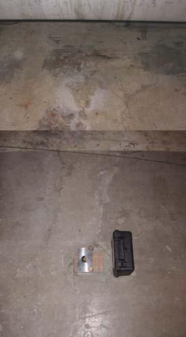
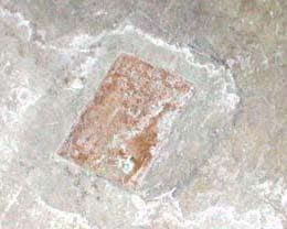
3 In the LinacTunnel Station-100 linac floor marker

4 LCLS Undulator Coordinate System E. Bong, P. Emma, C. LeCocq, T. Montagne, J. Welch LCLS-TN-03-8, April 16, %Nominal Slope of linac at Station-100 Definition of Station ft=3048m Values adopted for SLC R = m MSL= m
5 How to Access this Information at the Surface Level During the linac construction, it was well thought of and a new set of brass plates were installed in the klystron gallery. During PEP construction, a set of 8 monuments were established (see PEP Site Survey by the National Geodetic Survey also known PTM #85 R1). None of these marks have been used recently. During the SLC construction, a set of 7 pillars and 5 other markers were installed around the campus and observed by a combination of theodolites, distancemeters and GPS observations: In the Research Yard, within the FFTB tunnel, the ESA and ESB buildings.

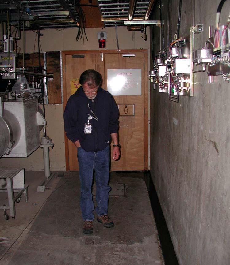
6 In the Klystron Gallery Typical Section of Klystron Gallery and 6 10 Accelerator Housing Brass Plate Alignment Reference Mark (6 x 4 ) Center Line Klystron Gallery Looking East SLAC Drawing # SK - GE A Accelerator Service Shaft 1 9 Center Line Accelerator Housing linac z axis 1 7 Accelerator Tube 2 9 Brass Plate Alignment Reference Mark (6 x 4 )
7 Station-100 In the linac system: Station-100 is: z=10000 x=0 y=0 Station-100 floor marker is: z=10000 x=-4 4 Station-100 klystron gallery marker is: z=10000 x=7 The transformation from the linac system to a leveled coordinate system centered at Station-100 is given by Z = cos(s 100 ) (z-z 100 ) + sin(s 100 ) y where s 100 = rad. Station-100 is: Z=0 X=0 Y=0 Station-100 floor marker is: Z = m assuming that the floor is about 1.9m down from the beam. This value of -9.2mm was entered without its sign in the alignment database. A memo dated 10/30/91 states this fact and outlined its impact on the new FFTB magnet locations. The main consequence is that the SLC coordinate system origin has its origin shifted improperly 18.4mm. One should be reminded too that the slope of the linac at Station-100 was chosen as % by the SLC designers instead of the % value for the linac design.
8 So Where is Station-100 in the Tunnel? During the Summer Downtime of 2004, AEG performed a specific survey in the area of Station-100 in order to get the as-built positions of quads 50Q1, 50Q2 and 50Q3 as well as bend 50B1. There are no fiducials on these quads, so center positions were obtained by a combination of surface shots and as-built dimensions. The adjustment was carried out in the SLC monuments system. Later the results were expressed in the pitched linac system using the nominal pitch value for the accelerator at Station-100, i.e rad. Pitched Linac SLC Monument System Z (m) X (m) Y (m) Z (m) X (m) Y (m) 50Q1M Q2M Q3M B1M JP30_8* JP30_9* Sta100M * The x offset for the jack point fixture is
9 2004 AEG Tunnel Analysis X Analysis The brass plate marker of Station-100 is measured at m. The design value as indicated in the drawing SK-GE-5153 A is 4 4, leading to a difference of about 5 mm. The previous local survey was made on January Here is a summary table of the x position in mm: Q1 Q2 Q3 JP8 JP Z Analysis In the note LCLS-TN-03-8, two values are quoted from the deck : Station-100 to Q m Station-100 to Q m The numbers from the previous slide are referring to Station-100 implied in the monument coordinates, i.e. the one used for SLC. They must then be shifted by -18.4mm as indicated in the 10/30/91 alignment memo: Station-100 to Q = m Station-100 to Q = m The comparison of these two sets of numbers show a discrepancy of about 2 mm for Q1 and 28 mm for Q2. The same alignment memo states that In October 1984, Q2 was moved upstream 2.5 cm because of mechanical interference with its installation. With this in mind the 2004 measured z positions for Q1 and Q2 are respectively 2 mm and 3 mm upstream. Because of the choice of instrumentation, the limited geometry for the resections, the absence of fiducials on the quads and the difficulty to center on a mark on a brass plate, 0.5mm is a reasonable guess for the RMS on these z measurements.
10 2004 AEG Work for LCLS Layout Because of our GPS base station, AEG is now able to produce State Plane Coordinates for all outside work on the SLAC site: A transformation between SLAC and State grid has been established based on the following points: Klystron gallery brass plates for sectors 1, 2, 3, 21, 28, 29, 30 M20 under metallic tower SLC pillars: AAA, M32, M33, M36, M40, M41 Research yard points: SPPS010, 020, 040, 060, 070, 080, 090
11 SLAC-State Grid Transformation Z ZM40 X XM40 = k cos α sin α - sin α cos α E EM40 N NM40 ZM40 = m α = EM40 = m XM40 = m k = NM40 = m E EM40 N NM40 cos α -sin α sin α cos α = k -1 Z ZM40 X XM40 N.B. This model has been designed for general mapping purposes. It is a cm transformation.

12 So Where is Station-100 in the Open?
Preliminary Layout for LCLS. Direction Stake-out
 Preliminary Layout for LCLS Direction Stake-out Scope of the Job Part 1 Mark the direction of the accelerator in the research yard and to the radiation fence. Chosen solution: Use existing feature such
Summer / Fall 2004 Downtime AEG Preparation Work
 Summer / Fall 2004 Downtime AEG Preparation Work In general the Alignment Engineering Group consulted with individuals involved in many of the scheduled downtime activities. Equipment was checked, manpower
LCLS RF Reference and Control R. Akre Last Update Sector 0 RF and Timing Systems
 LCLS RF Reference and Control R. Akre Last Update 5-19-04 Sector 0 RF and Timing Systems The reference system for the RF and timing starts at the 476MHz Master Oscillator, figure 1. Figure 1. Front end
A Facility for Accelerator Physics and Test Beam Experiments
 A Facility for Accelerator Physics and Test Beam Experiments U.S. Department of Energy Review Roger Erickson for the FACET Design Team February 20, 2008 SLAC Overview with FACET FACET consists of four
Electron Bypass Line (EBL) Design Electrons to A-line bypassing LCLS T. Fieguth, R. Arnold
 Design Electrons to A-line bypassing LCLS T. Fieguth, R. Arnold") September 2007 SLAC-TN-08-001 Electron Bypass Line (EBL) Design Electrons to A-line bypassing LCLS T. Fieguth, R. Arnold Introduction Forty one years ago, September 20, 1966, the first beam entered End
September 2007 SLAC-TN-08-001 Electron Bypass Line (EBL) Design Electrons to A-line bypassing LCLS T. Fieguth, R. Arnold Introduction Forty one years ago, September 20, 1966, the first beam entered End
Requirements for the Beam Abort Magnet and Dump
 Requirements for the Beam Abort Magnet and Dump A beam abort kicker (pulsed dipole magnet) and dump are required upbeam of the LCLS undulator in order to protect the undulator from mis-steered and poor
SABER A Facility for Accelerator Physics and Test Beam Experiments Roger Erickson SABER Workshop March 15, 2006
 SABER A Facility for Accelerator Physics and Test Beam Experiments Roger Erickson SABER Workshop March 15, 2006 FFTB will soon be gone! The Problem: On April 10, 2006, the Final Focus Test Beam (FFTB)
SLAC ILC Accelerator R&D Program
 SLAC ILC Accelerator R&D Program SLUO Meeting September 26 th, 2005 Tor Raubenheimer SLAC 2005 ILC Program NLC group was redirected towards ILC Developed a program aimed at the topics identified in the
LCLS Injector Technical Review
 LCLS Injector Technical Review Stanford Linear Accelerator Center November 3&4 2003 Review Committee Members: Prof. Patrick O Shea Chair University of Maryland Dr. E. Colby Stanford Linear Accelerator
P. Emma, et al. LCLS Operations Lectures
 P. Emma, et al. LCLS Operations Lectures LCLS 1 LCLS Accelerator Schematic 6 MeV 135 MeV 250 MeV σ z 0.83 mm σ z 0.83 mm σ z 0.19 mm σ δ 0.05 % σ δ 0.10 % σ δ 1.6 % Linac-0 L =6 m rf gun L0-a,b Linac-1
PEP-II Overview & Ramp Down Plan. J. Seeman DOE PEP-II Ramp Down-D&D Review August 6-7, 2007
 PEP-II Overview & Ramp Down Plan J. Seeman DOE PEP-II Ramp Down-D&D Review August 6-7, 2007 Topics Overview of the PEP-II Collider PEP-II turns off September 30, 2008. General list of components and buildings
Proceedings of the 1972 Proton Linear Accelerator Conference, Los Alamos, New Mexico, USA ALIGNMENT PHILOSOPHY, DESIGN AND TECHNIQUES USED AT LAMPF*
 ALIGNMENT PHILOSOPHY, DESIGN AND TECHNIQUES USED AT LAMPF* Elbert W. Colston and Valgene E. Hart University of California Los Alamos Scientific Laboratory Los Alamos, New Mexico A b.6 Vtac;t. TfU!., papejt
PEP II Design Outline
 PEP II Design Outline Balša Terzić Jefferson Lab Collider Review Retreat, February 24, 2010 Outline General Information Parameter list (and evolution), initial design, upgrades Collider Ring Layout, insertions,
Future Performance of the LCLS
 Future Performance of the LCLS J. Welch for many* SLAC National Accelerator Laboratory FLS 2010, ICFA Beam Dynamics Workshop on Future Light Sources, March 1-5, 2010. SLAC National Accelerator Laboratory,
Week 0: PPS Certification and Processing. Mon Feb 11 Tue Feb 12 Wed Feb 13 Thu Feb 14 Fri Feb 15 Sat Feb 16 Sun Feb 17
 Week 0: PPS Certification and Processing Mon Feb 11 Tue Feb 12 Wed Feb 13 Thu Feb 14 Fri Feb 15 Sat Feb 16 Sun Feb 17 Work in tunnel Work in tunnel PPS Certification PPS Certification PPS Certification
Upgrading LHC Luminosity
 1 Upgrading LHC Luminosity 2 Luminosity (cm -2 s -1 ) Present (2011) ~2 x10 33 Beam intensity @ injection (*) Nominal (2015?) 1 x 10 34 1.1 x10 11 Upgraded (2021?) ~5 x10 34 ~2.4 x10 11 (*) protons per
Tolerances on Magnetic Misalignments in SESAME Storage Ring
 Tolerances on Magnetic Misalignments in SESAME Storage Ring SES-TE-AP-TN-0003 April 20, 2014 Authored by: Reviewed by: Approved by: Access List : Maher Attal Erhard Huttle Erhard Huttle ---Internal ---------
PEP-II IR-2 Alignment
 SLAC-PUB-10328 January 2004 PEP-II IR-2 Alignment A. Seryi, S. Ecklund, C. Le Cocq, R. Pushor, R. Ruland, Z. Wolf SLAC, Stanford, CA 94025, USA This paper describes the first results and preliminary analysis
Oak Ridge Spallation Neutron Source Proton Power Upgrade Project and Second Target Station Project
 Oak Ridge Spallation Neutron Source Proton Power Upgrade Project and Second Target Station Project Workshop on the future and next generation capabilities of accelerator driven neutron and muon sources
Energy Upgrade Options for the LCLS-I Linac
 Energy Upgrade Options for the LCLS-I Linac LCLS-II TN-14-10 11/12/2014 John Sheppard, F.J. Decker, R. Iverson, H.D. Nuhn, M. Sullivan, J. Turner November 18, 2014 LCLSII-TN-14-07 LCLS 1 Linac Energy Increase
Top-Up Experience at SPEAR3
 Top-Up Experience at SPEAR3 Contents SPEAR 3 and the injector Top-up requirements Hardware systems and modifications Safety systems & injected beam tracking Interlocks & Diagnostics SPEAR3 Accelerator
STATUS OF THE SWISSFEL C-BAND LINEAR ACCELERATOR
 Proceedings of FEL213, New York, NY, USA STATUS OF THE SWISSFEL C-BAND LINEAR ACCELERATOR F. Loehl, J. Alex, H. Blumer, M. Bopp, H. Braun, A. Citterio, U. Ellenberger, H. Fitze, H. Joehri, T. Kleeb, L.
PEP II STATUS AND PLANS *
 PEP II STATUS AND PLANS * John T. Seeman + Stanford Linear Accelerator Center, Stanford University, Stanford, CA 94309 USA The PEP II B-Factory 1 project is an e + e - colliding beam storage ring complex
. SLAC-P~ December 1995
 SLAC-P~-95-7058 December 1995 BEAM-BASED ALIGNMENT OF THE FINAL FOCUS TEST BEAM * P. Tenenbaum, D. Burke, R. Helm, J. Iwin, P. Raimondi Stanford Linear Accelerator Center, Stanford University, Stanford,
PEP-II Disassembly Technical Systems
 PEP-II Disassembly Technical Systems PEP-II D&D Review 6-Aug-2007 S.DeBarger S.Ecklund, A.Hill, D.Kharakh, M.Zurawel Outline Project safety Disassembly of technical systems Shielding Vac/Mechanical Cable
Linac 4 Instrumentation K.Hanke CERN
 Linac 4 Instrumentation K.Hanke CERN CERN Linac 4 PS2 (2016?) SPL (2015?) Linac4 (2012) Linac4 will first inject into the PSB and then can be the first element of a new LHC injector chain. It will increase
DEVELOPMENT OF A 10 MW SHEET BEAM KLYSTRON FOR THE ILC*
 DEVELOPMENT OF A 10 MW SHEET BEAM KLYSTRON FOR THE ILC* D. Sprehn, E. Jongewaard, A. Haase, A. Jensen, D. Martin, SLAC National Accelerator Laboratory, Menlo Park, CA 94020, U.S.A. A. Burke, SAIC, San
PEP II Status and Plans
 SLAC-PUB-6854 September 1998 PEP II Status and Plans By John T. Seeman Invited talk presented at the 16th IEEE Particle Accelerator Conference (PAC 95) and International Conference on High Energy Accelerators,
Next Linear Collider. The 8-Pack Project. 8-Pack Project. Four 50 MW XL4 X-band klystrons installed on the 8-Pack
 The Four 50 MW XL4 X-band klystrons installed on the 8-Pack The Demonstrate an NLC power source Two Phases: 8-Pack Phase-1 (current): Multi-moded SLED II power compression Produce NLC baseline power: 475
Availability and Reliability Issues for the ILC
 Availability and Reliability Issues for the ILC SLAC Presented at PAC07 26 June 07 Contents Introduction and purpose of studies The availability simulation What was modeled (important assumptions) Some
Status of CTF3. G.Geschonke CERN, AB
 Status of CTF3 G.Geschonke CERN, AB CTF3 layout CTF3 - Test of Drive Beam Generation, Acceleration & RF Multiplication by a factor 10 Drive Beam Injector ~ 50 m 3.5 A - 2100 b of 2.33 nc 150 MeV - 1.4
Program Risks Risk Analysis Fallback Plans for the. John T. Seeman DOE PEP-II Operations Review April 26, 2006
 Program Risks Risk Analysis Fallback Plans for the PEP-II B-FactoryB John T. Seeman DOE PEP-II Operations Review April 26, 2006 OPS Review Topics Are there any PEP-II program risks? Has the laboratory
Tutorial: Trak design of an electron injector for a coupled-cavity linear accelerator
 Tutorial: Trak design of an electron injector for a coupled-cavity linear accelerator Stanley Humphries, Copyright 2012 Field Precision PO Box 13595, Albuquerque, NM 87192 U.S.A. Telephone: +1-505-220-3975
Scavenger Extraction. Karen Goldsmith Shawn Alverson
 Scavenger Extraction Karen Goldsmith Shawn Alverson Topics Beam line and area maps High Power Target (HPT) How to establish first beam to HPT Setting energy (configs, multiknobs, Fast Phase Shifters, etc.)
SLAC ILC program, International BDS Design, ATF2 facility
 1 May 3, 2005 SLAC ILC program, International BDS Design, ATF2 facility Andrei Seryi May 3, 2005 Seminar at CERN 2 May 3, 2005 Contents SLAC ILC program» following the outline given by Tor Raubenheimer
Advanced Photon Source - Upgrades and Improvements
 Advanced Photon Source - Upgrades and Improvements Horst W. Friedsam, Jaromir M. Penicka Argonne National Laboratory, Argonne, Illinois, USA 1. INTRODUCTION The APS has been operational since 1995. Recently
CLEX (CLIC Experimental Area)
") CLEX (CLIC Experimental Area) Status and plans G.Geschonke for Hans Braun CERN CT3 coll meetg 2005 CLEX 1 CT3 objectives R1.1 CLIC accelerating structure, R1.2 rive beam scheme with a fully loaded linac
CLEX (CLIC Experimental Area) Status and plans G.Geschonke for Hans Braun CERN CT3 coll meetg 2005 CLEX 1 CT3 objectives R1.1 CLIC accelerating structure, R1.2 rive beam scheme with a fully loaded linac
RF considerations for SwissFEL
 RF considerations for H. Fitze in behalf of the PSI RF group Workshop on Compact X-Ray Free Electron Lasers 19.-21. July 2010, Shanghai Agenda Introduction RF-Gun Development C-band development Summary
Preparations for Installation, Testing and Commissioning based on Experience at CERN, SNS and Siemens
 Preparations for Installation, Testing and Commissioning based on Experience at CERN, SNS and Siemens Eugène Tanke FRIB / MSU ESS Seminar, Lund, 6 March 2013 Outline Project Goal for the Accelerator Path
Accelerator Instrumentation RD. Monday, July 14, 2003 Marc Ross
 Monday, Marc Ross Linear Collider RD Most RD funds address the most serious cost driver energy The most serious impact of the late technology choice is the failure to adequately address luminosity RD issues
Towards an X-Band Power Source at CERN and a European Structure Test Facility
 Towards an X-Band Power Source at CERN and a European Structure Test Facility Erk Jensen and Gerry McMomagle CERN The X-Band Accelerating Structure Design and Test-Program Workshop Day 2: Structure Testing
Status and Plans for PEP-II
 Status and Plans for PEP-II John Seeman SLAC Particle and Particle-Astrophysics DOE HEPAP P5 Review April 21, 2006 Topics Luminosity records for PEP-II in October 2005 Fall shut-down upgrades Run 5b turn
Beam Losses During LCLS Injector Phase-1 1 Operation
 Beam Losses During LCLS Injector Phase-1 1 Operation & Paul Emma September 28, 2006 Radiation Safety Committee Review Scope of Phase 1 Operation Request for Three Operating Modes Operating Plan for Phase
Development of Multiple Beam Guns for High Power RF Sources for Accelerators and Colliders
 SLAC-PUB-10704 Development of Multiple Beam Guns for High Power RF Sources for Accelerators and Colliders R. Lawrence Ives*, George Miram*, Anatoly Krasnykh @, Valentin Ivanov @, David Marsden*, Max Mizuhara*,
The PEFP 20-MeV Proton Linear Accelerator
 Journal of the Korean Physical Society, Vol. 52, No. 3, March 2008, pp. 721726 Review Articles The PEFP 20-MeV Proton Linear Accelerator Y. S. Cho, H. J. Kwon, J. H. Jang, H. S. Kim, K. T. Seol, D. I.
30 GHz Power Production / Beam Line
 30 GHz Power Production / Beam Line Motivation & Requirements Layout Power mode operation vs. nominal parameters Beam optics Achieved performance Problems Beam phase switch for 30 GHz pulse compression
RADIATION SAFETY SYSTEM OF THE B-FACTORY AT THE STANFORD LINEAR ACCELERATOR CENTER
 SLAC-PUB-7786 (August 1998) RADIATION SAFETY SYSTEM OF THE B-FACTORY AT THE STANFORD LINEAR ACCELERATOR CENTER J. C. Liu, X. S. Mao, W. R. Nelson, J. Seeman, D. Schultz, G. Nelson, P. Bong, B. Gray Stanford
Diamond RF Status (RF Activities at Daresbury) Mike Dykes
 Mike Dykes") Diamond RF Status (RF Activities at Daresbury) Mike Dykes ASTeC What is it? What does it do? Diamond Status Linac Booster RF Storage Ring RF Summary Content ASTeC ASTeC was formed in 2001 as a centre of
Diamond RF Status (RF Activities at Daresbury) Mike Dykes ASTeC What is it? What does it do? Diamond Status Linac Booster RF Storage Ring RF Summary Content ASTeC ASTeC was formed in 2001 as a centre of
A Novel Wire Scanner for High Intensity Pulsed Beams *
 SLAC-PUB-806 1 February 1999 A Novel Wire Scanner for High Intensity Pulsed Beams * C.H. Back+, F. King, G. Collet, R. Kirby and C. Field Stanford Linear Accelerator Center, Stanford University, Stanford,
AREAL- Phase 1. B. Grigoryan on behalf of AREAL team
 AREAL- Phase 1 Progress & Status B. Grigoryan on behalf of AREAL team Contents Machine Layout Building & Infrastructure Laser System RF System Vacuum System Cooling System Control System Beam Diagnostics
Periodic Seasonal Variation of Magnets Level of the STB ring
 Periodic Seasonal Variation of Magnets Level of the STB ring Shigenobu Takahashi Laboratory of Nuclear Science,Tohoku University, Mikamine 1-2-1, Taihaku-ku, Sendai 982-0826, Japan 1. Introduction The
Workshop on Accelerator Operations August 6-10, 2012 Glen D. Johns Accelerator Operations Manager
 HWDB: Operations at the Spallation Neutron Source Workshop on Accelerator Operations August 6-10, 2012 Glen D. Johns Accelerator Operations Manager Outline Facility overview Organization Shift schedule
US-ILC Waveguide Industrialization Study. Marc Ross, Chris Nantista and Chris Adolphsen
 US-ILC Waveguide Industrialization Study Marc Ross, Chris Nantista and Chris Adolphsen ILC Local Power Distribution System (LPDS) variable power divider, pressurizable, 0-100%, phase stable pressure window
PEP-II STATUS REPORT *
 PEP-II STATUS REPORT * Jonathan Dorfan Stanford Linear Accelerator Center, Stanford University, Stanford, CA 94309 USA For the SLAC, LBNL, LLNL PEP-II group Abstract The main design features of the PEP-II
TWO BUNCHES WITH NS-SEPARATION WITH LCLS*
 TWO BUNCHES WITH NS-SEPARATION WITH LCLS* F.-J. Decker, S. Gilevich, Z. Huang, H. Loos, A. Marinelli, C.A. Stan, J.L. Turner, Z. van Hoover, S. Vetter, SLAC, Menlo Park, CA 94025, USA Abstract The Linac
4.4 Injector Linear Accelerator
 4.4 Injector Linear Accelerator 100 MeV S-band linear accelerator based on the components already built for the S-Band Linear Collider Test Facility at DESY [1, 2] will be used as an injector for the CANDLE
Experience with the Cornell ERL Injector SRF Cryomodule during High Beam Current Operation
 Experience with the Cornell ERL Injector SRF Cryomodule during High Beam Current Operation Matthias Liepe Assistant Professor of Physics Cornell University Experience with the Cornell ERL Injector SRF
THE OPERATION OF A CATHODE RAY TUBE
 THE OPERATION OF A CATHODE RAY TUBE OBJECT: To acquaint the student with the operation of a cathode ray tube, and to study the effect of varying potential differences on accelerated electrons. THEORY:
First Simultaneous Top-up Operation of Three Different Rings in KEK Injector Linac
 First Simultaneous Top-up Operation of Three Different Rings in KEK Injector Linac Masanori Satoh (Acc. Lab., KEK) for the injector upgrade group 2010/9/16 1 Overview of Linac Beam Operation 2010/9/16
Detailed Design Report
 Detailed Design Report Chapter 4 MAX IV Injector 4.6. Acceleration MAX IV Facility CHAPTER 4.6. ACCELERATION 1(10) 4.6. Acceleration 4.6. Acceleration...2 4.6.1. RF Units... 2 4.6.2. Accelerator Units...
RF Design of the LCLS Gun C.Limborg, Z.Li, L.Xiao, J.F. Schmerge, D.Dowell, S.Gierman, E.Bong, S.Gilevich February 9, 2005
 RF Design of the LCLS Gun C.Limborg, Z.Li, L.Xiao, J.F. Schmerge, D.Dowell, S.Gierman, E.Bong, S.Gilevich February 9, 2005 Summary Final dimensions for the LCLS RF gun are described. This gun, referred
Physics Requirements for the CXI Ion Time-of-Flight
 PHYSICS REQUIREMENT DOCUMENT (PRD) Doc. No. SP-391-000-30 R0 LUSI SUB-SYSTEM CXI Physics Requirements for the CXI Ion Time-of-Flight Sébastien Boutet CXI Scientist, Author Paul Montanez CXI Lead Engineer
Focus of efforts. ILC 2010, Mar/27/10 A. Seryi, BDS: 2
 Beam Delivery System Updates Andrei Seryi for BDS design and ATF2 commissioning teams LCWS 2010 / ILC 2010 March 28, 2010 Plan of the program at ILC2010 Focus of efforts Work on parameter set for a possible
Status of SOLARIS Arkadiusz Kisiel
 Status of SOLARIS Arkadiusz Kisiel Solaris National Synchrotron Light Source Jagiellonian University Czerwone Maki 98 30-392 Kraków www.synchrotron.uj.edu.pl Arkadiusz.Kisiel@uj.edu.pl On behalf of SOLARIS
CHAPTER 3 OSCILLOSCOPES AND SIGNAL GENERATOR
 CHAPTER 3 OSCILLOSCOPES AND SIGNAL GENERATOR OSCILLOSCOPE 3.1 Introduction The cathode ray oscilloscope (CRO) provides a visual presentation of any waveform applied to the input terminal. The oscilloscope
Present Status and Future Upgrade of KEKB Injector Linac
 Present Status and Future Upgrade of KEKB Injector Linac Kazuro Furukawa, for e /e + Linac Group Present Status Upgrade in the Near Future R&D towards SuperKEKB 1 Machine Features Present Status and Future
Status of BESSY II and berlinpro. Wolfgang Anders. Helmholtz-Zentrum Berlin for Materials and Energy (HZB) 20th ESLS-RF Meeting
 20th ESLS-RF Meeting") Status of BESSY II and berlinpro Wolfgang Anders Helmholtz-Zentrum Berlin for Materials and Energy (HZB) 20th ESLS-RF Meeting 16.-17.11.2016 at PSI Outline BESSY II Problems with circulators Landau cavity
Status of BESSY II and berlinpro Wolfgang Anders Helmholtz-Zentrum Berlin for Materials and Energy (HZB) 20th ESLS-RF Meeting 16.-17.11.2016 at PSI Outline BESSY II Problems with circulators Landau cavity
LCLS Linac Technical Design Review Diagnostics and Controls
 Linac Coherent Light Source Stanford Synchrotron Radiation Laboratory Linac Technical Design Review Diagnostics and Controls December 12, 12, 2003 Requirements for for beamline instrumentation Upgrades
STATUS OF THE EUROPEAN XFEL CONSTRUCTING THE 17.5 GEV SUPERCONDUCTING LINEAR ACCELERATOR
 STATUS OF THE EUROPEAN XFEL CONSTRUCTING THE 17.5 GEV SUPERCONDUCTING LINEAR ACCELERATOR Winfried Decking, DESY for the European XFEL Accelerator Consortium Up to 17.5 GeV SC Linac, 27000 pulses per second
LCLS-II Injector Tuning Procedures. F. Zhou (SLAC) & F. Sannibale (LBNL) 2/6/2017
 & F. Sannibale (LBNL) 2/6/2017") LCLSII-TN-17-3 LCLS-II Injector Tuning Procedures F. Zhou (SLAC) & F. Sannibale (LBNL) /6/17 1. Introduction Figure 1 shows
LCLSII-TN-17-3 LCLS-II Injector Tuning Procedures F. Zhou (SLAC) & F. Sannibale (LBNL) /6/17 1. Introduction Figure 1 shows
Design Studies For The LCLS 120 Hz RF Gun Injector
 BNL-67922 Informal Report LCLS-TN-01-3 Design Studies For The LCLS 120 Hz RF Gun Injector X.J. Wang, M. Babzien, I. Ben-Zvi, X.Y. Chang, S. Pjerov, and M. Woodle National Synchrotron Light Source Brookhaven
INSTRUMENT CATHODE-RAY TUBE
 Instrument cathode-ray tube D14-363GY/123 INSTRUMENT CATHODE-RAY TUBE mono accelerator 14 cm diagonal rectangular flat face internal graticule low power quick heating cathode high brightness, long-life
PRESENT STATUS OF J-PARC
 PRESENT STATUS OF J-PARC # F. Naito, KEK, Tsukuba, Japan Abstract Japan Proton Accelerator Research Complex (J-PARC) is the scientific facility with the high-intensity proton accelerator aiming to realize
Current status of XFEL/SPring-8 project and SCSS test accelerator
 Current status of XFEL/SPring-8 project and SCSS test accelerator Takahiro Inagaki for XFEL project in SPring-8 inagaki@spring8.or.jp Outline (1) Introduction (2) Key technology for compactness (3) Key
RSH27 Nixie Tube Socket with LED
 Contents: 1. Applications of the socket 2. Solder instructions of the socket 3. Drawing of the assembled socket 4. Section drawing of the socket with IN-8 tube 5. Drawing and technical data of the tube
THE OPERATION OF A CATHODE RAY TUBE
 THE OPERATION OF A CATHODE RAY TUBE OBJECT: To acquaint the student with the operation of a cathode ray tube, and to study the effect of varying potential differences on accelerated electrons. THEORY:
HIGH POWER BEAM DUMP AND TARGET / ACCELERATOR INTERFACE PROCEDURES *
 HIGH POWER BEAM DUMP AND TARGET / ACCELERATOR INTERFACE PROCEDURES * J. Galambos, W. Blokland, D. Brown, C. Peters, M. Plum, Spallation Neutron Source, ORNL, Oak Ridge, TN 37831, U.S.A. Abstract Satisfying
Status of Elettra, top-up and other upgrades
 Status of Elettra, top-up and other upgrades Emanuel Karantzoulis ELETTRA / Trieste, Italy / 2010 November 25-26 Past and Present Configurations 1994-2007 From 2008 No full energy injection Full energy
FINAL DESIGN OF ILC RTML EXTRACTION LINE FOR SINGLE STAGE BUNCH COMPRESSOR
 BNL-94942-2011-CP FINAL DESIGN OF ILC RTML EXTRACTION LINE FOR SINGLE STAGE BUNCH COMPRESSOR S. Sletskiy and N. Solyak Presented at the 2011 Particle Accelerator Conference (PAC 11) New York, NY March
Extraction/Separator Setup. Michael Spata Operations Stay Treat July 16, 2015
 Extraction/Separator Setup Michael Spata Operations Stay Treat July 16, 2015 Accelerator Overview Extraction System Design settings for magnets and RF Separators come from CED All beamlines have been commissioned
The Construction Status of CSNS Linac
 The Construction Status of CSNS Linac Sheng Wang Dongguan branch, Institute of High Energy Physics, CAS Sep.2, 2014, Geneva Outline The introduction to CSNS accelerators The commissoning of ion source
Monthly Progress Report Stanford Synchrotron Radiation Laboratory
 Monthly Progress Report Stanford Synchrotron Radiation Laboratory April 2003 TABLE OF CONTENTS A. Project Summary 1. Technical Progress 3 2. Cost Data 5 B. Design and Fabrication Reports 1.1 Magnets &
SPEAR 3: Operations Update and Impact of Top-Off Injection
 SPEAR 3: Operations Update and Impact of Top-Off Injection R. Hettel for the SSRL ASD 2005 SSRL Users Meeting October 18, 2005 SPEAR 3 Operations Update and Development Plans Highlights of 2005 SPEAR 3
Quad-to-quad correlated motion in FLASH
 Quad-to-quad correlated motion in FLASH Ramila Amirikas, Alessandro Bertolini DESY Hamburg Quad-to-quad correlated motion in FLASH Introduction- The experiment - continuous monitoring of vibrations in
Radiation containment at a1mwhigh energy electron accelerator:
 Radiation containment at a1mwhigh energy electron accelerator: Status of LCLS-II radiation physics design M. Santana Leitner 1,a, J. Blaha, M. W. Guetg, Z. Li, J. C. Liu, S. X. Mao, L. Nicolas, S. H. Rokni,
The Elettra Storage Ring and Top-Up Operation
 The Elettra Storage Ring and Top-Up Operation Emanuel Karantzoulis Past and Present Configurations 1994-2007 From 2008 5000 hours /year to the users 2010: Operations transition year Decay mode, 2 GeV (340mA)
Teltron Delection Tube D
 Teltron Delection Tube D 1011119 Overview The electron-beam deflection tube is intended for investigating the deflection of electron beams in electrical and magnetic fields. It can be used to estimate
Thoughts on Project Standard in Japan
 Thoughts on Project Standard in Japan August 16, 2005 H. Hayano, KEK Thoughts on project standard in Japan Production is industry-base, almost all-case. 1. Industry makes every detail drawings. 2. (Big)
DELIVERY RECORD. Location: Ibaraki, Japan
 DELIVERY RECORD Client: Japan Atomic Energy Agency (JAEA) High Energy Accelerator Research Organization (KEK) Facility: J-PARC (Japan Proton Accelerator Research Complex) Location: Ibaraki, Japan 1 October
The ESS Accelerator. For Norwegian Industry and Research. Oslo, 24 Sept Håkan Danared Deputy Head Accelerator Division Group Leader Beam Physics
 The ESS Accelerator For Norwegian Industry and Research Oslo, 24 Sept 2013 Håkan Danared Deputy Head Accelerator Division Group Leader Beam Physics The Hadron Intensity Frontier Courtesy of M. Seidel (PSI)
ESS: The Machine. Bucharest, 24 April Håkan Danared Deputy Head Accelerator Division. H. Danared Industry & Partner Days Bucharest Page 1
 ESS: The Machine Bucharest, 24 April 2014 Håkan Danared Deputy Head Accelerator Division H. Danared Industry & Partner Days Bucharest Page 1 2025 ESS construction complete 2009 Decision: ESS will be built
THE OPERATION EXPERIENCE AT KOMAC*
 THAM2X01 Proceedings of HB2016, Malmö, Sweden THE OPERATION EXPERIENCE AT KOMAC* Yong-Sub Cho, Kye-Ryung Kim, Kui Young Kim, Hyeok-Jung Kwon, Han-Sung Kim, Young-Gi Song Korea Atomic Energy Research Institute,
Technology Challenges for SRF Guns as ERL Sources in View of Rossendorf work
 Technology Challenges for SRF Guns as ERL Sources in View of Rossendorf work, Hartmut Buettig, Pavel Evtushenko, Ulf Lehnert, Peter Michel, Karsten Moeller, Petr Murcek, Christof Schneider, Rico Schurig,
Digital BPMs and Orbit Feedback Systems
 Digital BPMs and Orbit Feedback Systems, M. Böge, M. Dehler, B. Keil, P. Pollet, V. Schlott Outline stability requirements at SLS storage ring digital beam position monitors (DBPM) SLS global fast orbit
WHAT IS NEW AT CERN?
 WHAT IS NEW AT CERN? Dominique Missiaen, Antje Behrens, Patrick Bestmann, Jean-Frédéric Fuchs, Jean- Christophe Gayde, Mark Jones, Hélène Mainaud Durand, Antonio Marin, Dirk Mergelkuhl, Mateusz Sosin,
Riccardo Farinelli. Charge Centroid Feasibility
 Riccardo Farinelli Charge Centroid Feasibility Outline Prototype and TB setup Data set studied Analysis approch Results Charge Centroid Feasibility Ferrara July 07, 2015 R.Farinelli 2 Test chambers Conversion
Low-Energy Electron Linacs and Their Applications in Cargo Inspection
 Low-Energy Electron Linacs and Their Applications in Cargo Inspection Yawei Yang on behalf of Huaibi Chen *,1, Chuanxiang Tang 1 Yaohong Liu 2 *chenhb@tsinghua.edu.cn 1 Department of Engineering Physics,
Results of Vibration Study for LCLS-II Construction in FEE, Hutch 3 LODCM and M3H 1
 LCLS-TN-12-4 Results of Vibration Study for LCLS-II Construction in FEE, Hutch 3 LODCM and M3H 1 Georg Gassner SLAC August 30, 2012 Abstract To study the influence of LCLS-II construction on the stability
Suggested ILC Beam Parameter Range Rev. 2/28/05 Tor Raubenheimer
 The machine parameters and the luminosity goals of the ILC were discussed at the 1 st ILC Workshop. In particular, Nick Walker noted that the TESLA machine parameters had been chosen to achieve a high
Start to End Simulations
 Start to End Simulations Motivation, Methods, and Examples Michael Borland Operations Analysis Group APS Operations Division March 20, 2005 A Laboratory Operated by The University of Chicago Motivation