A Tour of PLDs. PLD ARCHITECTURES. [Prof.Ben-Avi]
|
|
|
- Gerard Cummings
- 5 years ago
- Views:
Transcription
1 [Prof.Ben-Avi]. (We shall now take a quick initial tour through the land of PLDs... the devices selected for this introductory tour have been chosen either because they are/were extremely popular or because they have/had particularly useful features that are/were also found in other devices. First let's discuss the different architectures of these devices. The architecture of a PLD affects the logic applications for which the device can be used. Currently, there are about 300 unique architectures of PLDs available. This number is constantly growing as manufacturers introduce new devices... I'll conclude this handout with an overview of current PLD technologies. Technology attributes include such things as manufacturing process (CMOS, bipolar, ECL, and so on), package type, speed grade, eraseability, and so forth. If we factor in all the available technology options, the number of distinct PLD's available rises into the many thousands. Technology differences affect how a programmed device will operate in a larger circuit, how the device is actually programmed, and in what kind of systems it can be utilized.) PLD ARCHITECTURES When we refer to the architecture of a PLD, we are referring to those device attributes that affect the logical construction of the device -- those attributes significant to the logic of a design to be implemented. Architectural attributes include such things as the configuration of the pins, the arrangement and size of the programmable array (s), and the configuration of the input and output interface logic. PROMs, PALs, and PLAs A programmable logic array is normally composed of a specific number of input lines connected through a fixed or programmable array to a set of AND gates, which are in turn connected to a fixed or programmable array of OR gates. The OR gates provide the output signals from the logic array. A simplified programmable logic array composed of two inputs and one output is shown in Figure 1. (1 of 81)12/27/2005 9:08:06 PM
2 Notice that, to provide all possible combinations of inputs, each input is routed to the array in both its true and complemented form. These inputs are then connected to AND gates via programmable interconnection points. These product terms are OR-ed together to form a sum-of-products logic array. Since a typical PLD has many more inputs and outputs than the simple array shown above, a special notation, called a logic diagram, is used to graphically describe the complex PLA structures associated with these devices. When the array is programmed to implement a particular logic function, the desired inter-connections can be indicated on the logic diagram with Xs. Figure 2 shows the two-input, one output logic array drawn in logic diagram form and programmed with a simple logic function. In some devices, the AND/OR structure is replaced by either NAND/NAND or NOR/NOR structures, (... remember de'morgan's laws?? Remember EE150?? Remember your name??), but the result is the same: with a large enough array, any logic function can be implemented. Programming of the device is accomplished by enabling or disabling interconnections in the device's programmable array. The actual connections can be provided in a variety of ways depending on the device technology. (2 of 81)12/27/2005 9:08:06 PM
3 Proms Programmable read-only memories (PROMs) are the oldest form of programmable logic devices, but were not actually designed for logic applications. PROMs have historically been used to store data such as boot-strap programs and micro-code instructions. They have also been used extensively for decoding functions and simple state machines (when provided with external storage registers) and as such can be considered programmable logic devices. The PROM structure can be used for any general purpose logic circuit since it incorporates a sumof-products logic array. The basic PROM array is shown in the logic diagram of Figure 3. (3 of 81)12/27/2005 9:08:06 PM
4 In this figure, all programmable fuse locations are indicated with Xs. To program this PROM array, you decide which of the interconnect points (each intersection of a horizontal and vertical line) are to be preserved, and disable the remaining connections. For a PROM with n inputs, there are 2 n possible input values, all of which are provided for in the AND array. The programmable OR array allows each of these input values to be decoded into any value consisting of k outputs, where k equals the number of OR gates (and corresponding outputs) in the array. This makes PROMs particularly well suited for read-only memory applications and this is their most common use. Since a PROM can map any of its input states into an arbitrary output state, it can be used quite effectively for implementing n-input, k-output combinational logic functions. Each unique input state corresponds to one unique product term in the array. To use a PROM for logic functions, the designer need only specify the truth table for the set of functions. There is no need for logic minimization since all possible input combinations are provided in the AND array. As we pointed out, a PROM provides the complete set of input combinations in the AND array. For most logic functions, however, this is completely unnecessary, and results in a tremendous amount of wasted circuitry on the chip. Particularly, when a large number of inputs are required, the PROM structure becomes impractical. Consider, for example, when a logic function of sixteen input variables and eight output variables is desired. To implement such a function in a PROM, you would have to use a 64K by 8 bit PROM device, regardless of the complexity of the logic function. A PROM of this size would be a highly inefficient vehicle for most logic functions. Most n-variable logic functions can be implemented with far less than 2 n product terms. To more efficiently map logic functions with a larger number of inputs, the PLA (programmable logic array) and PAL (programmable array logic) devices were developed. The PLA structure is the basis for virtually all PLDs in use today. The complete PLA structure is the basis for a variety of PLDs, and provides the greatest flexibility in how product terms are allocated to the OR gates and associated outputs. The PLA structure, shown in figure 4, features both a programmable AND-array, and a programmable OR array. (4 of 81)12/27/2005 9:08:06 PM

5 For a PLA with n inputs, any input variable (or its complement) may be an input to any AND gate. Therefore, any AND gate in the AND array can be configured to implement any of 3 n possible product terms (3 n because each input to an AND gate has three possible values true, complement, and no-connect). The design of the PLA (5 of 81)12/27/2005 9:08:06 PM
6 allows any product term in the array to be connected to the OR gate of any output. This feature is sometimes referred to as product-term-sharing. The PLA provides the most flexibility for implementing logic circuits, particularly for large designs in which many common logic elements can be shared between circuit outputs. PLA type devices are generally slower in operation than PROMs and PALs since there are two programmable arrays through which signals must propagate. Unlike a PROM, the total number of product terms available in a PLA is limited, so logic minimization is important when implementing designs. The PAL (programmable array logic) structure is similar to the PLA, but has a fixed OR array, as illustrated in Figure 5. (6 of 81)12/27/2005 9:08:06 PM
7 Every output in a standard PAL-type device has one OR gate that is unique to that output. There is no provision for product term sharing (although, as we shall see later, some PAL-based devices do allow for various forms of product term reallocation). These product terms are then gated together by fixed OR gates to drive the device outputs. As I said, since a limited number of product terms are provided for each PAL output, logic minimization techniques become important when logic circuits are implemented in PAL devices. PAL Devices The most common PALs in use today are the 16L8 and 16R4/6/8 series of devices. These 20-pin devices originated at MMI (now a part of AMD) are now available from many manufacturers. The devices are intended to replace standard logic parts and are, therefore, designed to operate with TTL (transistor-transistor logic) signal levels -- you can interconnect them freely with 74LSxx series chips from your EE150 kit. Combinational PALs Combinational PALs are those devices that are based on a PAL structure, and do not contain any memory elements. Combinational PALs are useful for a wide variety of random logic functions, including decoders, interface logic, and other applications that require a simple decoding of device inputs. The 16L8 represents the typical combinational PAL and is diagrammed in Figure 6. (7 of 81)12/27/2005 9:08:06 PM
8 The diagram for the 16L8 shows that the device has ten dedicated inputs (pins 1 through 9 and pin 11) to the programmable AND array. Each input to the array is available in its true or complemented form allowing any combination of the inputs to be expressed on any row of the array. Each row of the 16L8 array corresponds to one product term of the device. The 16L8 has eight outputs, each of which is fed by a seven-input OR gate. Each (8 of 81)12/27/2005 9:08:06 PM
.")
9 output of this device is capable of implementing a logic function composed of seven or fewer product terms. The eighth product term is used to control the three-state output buffer, the function of which we will examine in a moment. A simple logic function is shown implemented in the 16L8 in Figure 7(a). The X's shown on the diagram indicate fuse interconnections that have been left intact to implement the function. A large X inside of an unused AND gate indicates that all of the fuses for that row are to be disconnected. When all of the fusible links for a row are disconnected, the associated OR gate input floats high. Figure 7(b) shows the same logic function expressed as a traditional schematic. Notice that there is an inverter associated with the PAL output. There are PAL devices available that don't have the output inverter (often indicated with an H in the part name, such as, 16H8 instead of 16L8) but these devices are less frequently used since active-low logic is prevalent and these logic functions normally fit better in a PLD with inverted outputs. In addition to the dedicated inputs, there are six I/O pins (pins 13 through 18) on the device that may be used as array inputs as well. These pins can be used in a variety of ways. To use these I/O pins as dedicated inputs, you must disable the three-state output buffer associated with that pin. When a three-state buffer appears on the output of a PLD, it's called an output enable. (9 of 81)12/27/2005 9:08:06 PM
10 Since the output enable for the 16L8 is controlled from the array, you disable it by leaving intact the fuses for the dedicated product term that controls the enable. Leaving all of the fuses intact (or, for that matter, any pair of true and complement array inputs for a single input pin) for any product term in the device results in a logic level 0 on that product term. This is shown in Figure 8. Using the I/O pins as inputs, it's possible to use the 16L8 to implement logic functions with as many as sixteen separate inputs, at the expense of usable outputs. The I/O pins can also be used as dedicated outputs, by permanently enabling the output enable. This is done by blowing all of the fuses for the output enable's product term as was done in Figure 7(a). When all of the inputs to an AND gate in this device are disconnected, the AND gate floats high, in this case, enabling the output enable. When the output enable of a 16L8 I/O pin is enabled, the input to the array is still active, and can be used to feed the output back into the array. This is useful for multilevel logic applications (see later handouts). This feature can also be used to create oscillating or asynchronous sequencer circuits, although these applications aren't generally recommended. The most common use of the output enable is for traditional three-state purposes such as bus interfacing. To use the output enable dynamically, you simply program the output enable product term with the desired logic as shown in Figure 9. (10 of 81)12/27/2005 9:08:06 PM
11 Programmable Output Polarity Quite often, there are situations in which a design be implemented in a 16L8 or 16H8 due to the need for some of the outputs to be inverted while others are not. For these applications, a version of the 16L8 is available, called the 16P8 that has a feature called programmable output polarity. Figure 10 illustrates how programmable output polarity is implemented in the 16P8 device. To provide programmable output polarity, each output of the 16P8 includes an XOR gate. One input to this XOR is the output of one of the PAL's OR gates, while the other can be either connected to ground through a fuse or disconnected and allowed to float high. Some devices utilize other methods such as multiplexers or transmission gates for polarity control, but the result is the same. Other Related Combinational PALs There are a wide variety of simple PALs that have architectures similar to the 16L8. Most of these are stripped down versions that are somewhat less expensive. One of the least complex of these PALs is the 10L8, illustrated in Figure (11 of 81)12/27/2005 9:08:06 PM
12 (12 of 81)12/27/2005 9:08:06 PM
13 This device has only dedicated input and output pins, no output enable, and no feedback lines. The small number of product terms (sixteen total) and small number of inputs means that this device has only 320 fuses, and is only slightly more complex than a simple 32 by 8-bit PROM device. These smaller PAL devices are rapidly losing popularity, as most PLD users find that it's most economical (because of inventory costs) to use the 16L8 or 16P8 for all of their strictly combinational applications, rather than attempt to save a few pennies per device by using simpler PAL devices. Registered PALs The most commonly used registered PAL devices are represented by the 16R4, the 16R6, and the 16R8 devices. The 16R4 device is shown in Figure (13 of 81)12/27/2005 9:08:06 PM
14 The design of the 16R4 device is similar, in most respects, to that of the 16L8. The difference is found on output pins 14 through 17. These outputs feature edge-triggered D-type flip-flops. The Q output of each flip- flop is routed to the PAL output through the output enable and each flip-flop's?q output is routed back to the AND (14 of 81)12/27/2005 9:08:06 PM
15 array. Like the fed-back combinational signals on the other outputs, these signals are provided to the array in both their true and complement form. The flip-flops are all controlled by a common clock which is tied directly to pin 1 on the device. This implies, of course, that pin 1 be used as an input, as it can in the 16L8. This is also true of pin 11, which is used as a dedicated input for the output enable of the flip-flops. This method of enabling outputs is common to most of the simpler PAL devices. In general, combinational outputs are enabled from a product term, while registered outputs are enabled from a dedicated pin. Since no product term is used for the output enable of the registered outputs, the eighth product term is made available for use as an input to the OR gate for those outputs. For most applications that require output synchronization or state memory, the output enable feature will be used globally, so a complex output enable is not required. Another trade-off in the design of these devices' output enables is speed; a pin controlled output enable will have a faster pin-to-enable speed. The architecture of the 16R4 is well suited for simple state machine applications. The registered outputs can be dedicated for use as state memory registers, while the combinational outputs can be used for either state machine outputs or additional control inputs. Note that it isn't possible to use the registered output pins of the 16R4 as inputs under any circumstances. Implementing a Sequential Design in the 16R4 To show how devices like the 16R4 are used for sequential designs, we will implement a simple circuit. This design is a simple 4-bit counter, the Boolean equations for which are shown in Figure (15 of 81)12/27/2005 9:08:06 PM
16 The design file shown is written in the ABEL -- similar to OrCAD -- language and uses simple Boolean equations that represent the logic of the counter. In ABEL, the & symbol represents an AND operation, the # symbol represents an OR operation, and the! symbol represents a NOT operation. (16 of 81)12/27/2005 9:08:06 PM
17 How these equations were derived is not important -- you know how to design a synchronous counter from EE150; we won't go into the specifics of this counter design here. Simply accept the fact that this counter increments a 4-bit number by one every time the device is clocked. The design utilizes active low logic, so the values observed on the device's outputs will be the complement of the actual number stored in the registers. Figure 14 is the device. (17 of 81)12/27/2005 9:08:06 PM
18 The least significant bit of the counter (represented by the Q0 variable in the counter equations) is mapped to pin 14 of the device and requires the least logic of any of the counter outputs -- this is typical. The remaining bits of the counter, Q1 through Q3, require correspondingly more logic, since they must each decode the previous counter bits to determine whether a change in state is required. The JEDEC standard format file that corresponds to the counter design is shown in Figure 15. This file is created by ABEL (or OrCAD) and is used to download programming data to a device programmer. The rows of ones and zeroes represent fuse locations and corresponding fuse values where a one indicates a blown fuse and a zero indicates an intact fuse. (18 of 81)12/27/2005 9:08:06 PM

19 A timing diagram of the counter circuit is shown in Figure 16. The diagram shows the relationship between the 16R4's clock input and the resulting counter-values appearing on the counter's four outputs. As I said, to ensure that the counter can be initialized to a known value immediately after power-up, this counter has been provided with a synchronous clear input. (19 of 81)12/27/2005 9:08:06 PM
20 When the clock signal (pin 1) goes from low to high, the registers change state to reflect the new counter value, which then appears on the device outputs as logic level 1 for all outputs (corresponding to a counter value of 0). Since there is a delay between the time the new register values appear on the flip-flop outputs and the time these values propagate back through the programmable array, the counter's flip-flop inputs will require a certain amount of time to stabilize before being clocked again. This limits the speed at which this design can be operated. A timing diagram of the counter circuit is shown in figure 16. The diagram shows the relationship between the 16R4's clock input and the resulting counter values appearing on the counter's four outputs. To ensure that the counter can be initialized to a known value immediately after power-up, it has been provided with a synchronous clear input. When the clock signal (pin 1) goes from low to high, the registers change state to reflect the new counter value, which then appears on the device outputs as logic level 1 for all outputs (corresponding to a counter value of 0). Since there is a delay between the time the new register values appear on the flip-flop outputs and the time these values propagate back through the programmable array, the counter's flip-flop inputs will require a certain amount of time to stabilize before being clocked again. This limits the speed at which this design can be operated. For most applications, though, the propagation times are short enough that this speed constraint is of little concern. Other Devices of the 16R4 Variety The 16R6 and 16R8 devices are identical to the 16R4, the only difference being in the number of registered outputs. The 16R6 has six registered outputs and two combinational outputs, while the 16R8 has eight registered outputs and no combinational outputs. Twenty-four-pin versions of these devices are also available (such as the 20R4, 20R6, and 20R8 devices) and are in all respects identical to the 20-pin devices with the addition of four extra input pins. (20 of 81)12/27/2005 9:08:06 PM
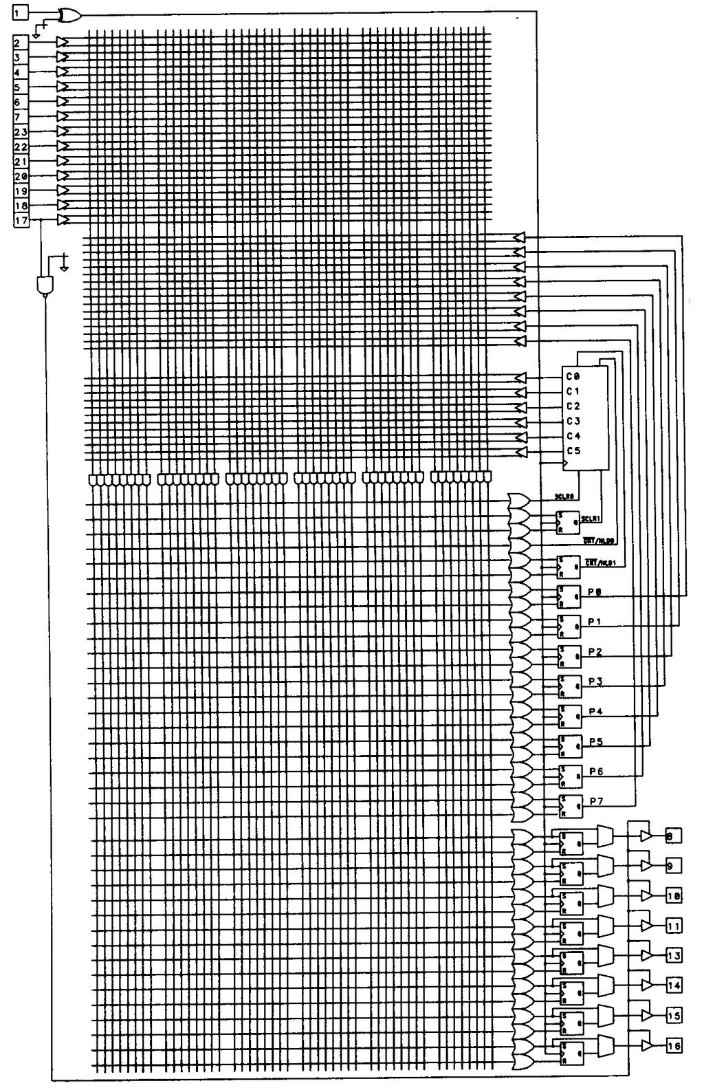
21 Configurable (Generic) PALs In recent years, configurable (sometimes called generic) device architectures have become extremely popular. These devices simplify procurement, qualification and inventory requirements by replacing a large number of simpler PAL type devices with a "one size fits all" device. In addition, their flexible architectures allow designs to be implemented that are challenging or simply impossible for the simpler PAL devices to handle. This architectural flexibility is provided by equipping the device with a variety of configuration fuses separate from those found in the programmable AND array. The 22V10 is one such device, and was designed by AMD to be a replacement for all of the 24-pin PALs of the architecture previously described. To meet this requirement, the 22V10 was designed with configurable outputs. These outputs are enhanced with special circuitry and are called output macrocells. Output macrocells are found on ten of the 22V10's pins, as shown in Figure (21 of 81)12/27/2005 9:08:06 PM

22 The 22V10 has a total of twelve dedicated inputs, one of which (pin 1) also functions as the common clock input to the edge-triggered D-type flip-flop of each output macrocell. Any of the 22V10's ten output pins can be used as inputs, so the device is capable of supporting applications requiring up to 22 inputs (of course, if you use all ten I/O pins as dedicated inputs, there is no way to observe the results of your efforts, since there will be no output pins left). We will examine the structure of the individual output macrocells momentarily, but first, notice that the number (22 of 81)12/27/2005 9:08:06 PM
23 of product terms available to the various OR gates in the device differs. The OR gate associated with pins 18 and 19, in fact, have sixteen product terms each available. This means that logic functions of significantly more complexity can be implemented in the 22V10. The irregular nature of the outputs does place more burden on the designer, though, since the design outputs may have to be assigned to device outputs based on their complexity. The complexity of the 22V10 results in a rather unwieldy logic diagram. For larger devices, the logic diagram format becomes completely impractical, so these devices are often presented in block diagram form. Figure 18 illustrates the 22V10 in block diagram form. (23 of 81)12/27/2005 9:08:06 PM
24 As I said, the 22V10 has ten output macrocells, all of which are identical. Figure 19 shows the construction of one of these output macrocells. (24 of 81)12/27/2005 9:08:06 PM
25 Each macrocell contains an edge-triggered D-type flip-flop and a pair of configurable multiplexers (I have shown the 22V10s configuration multiplexers complete with their fuse interconnections and pull-up resistors; in subsequent figures I shall omit the fuse and resistor). The two fuses that control the multiplexers can be configured in four different ways, as shown in Figure (25 of 81)12/27/2005 9:08:06 PM
26 The 22V10 also has available two extra product terms that can be seen in Figure 17. These product terms can be used for synchronously presetting the 22V10 registers, or asynchronously resetting them. The feedback in the 22V10 can be configured to be from the register, the output pin, or from the OR gate output. While AMD's 22V10 has the feedback path and register bypass configurations controlled with a single fuse. TI's 22VP10, on the other hand, has independently configurable feedback and register bypass. Another example of a configurable PAL is the Lattice GAL (generic array logic) device. These devices, more so even than the 22V10, are intended as pin-for-pin replacements for a wide variety of PAL devices. The GAL device, in fact, is designed to be compatible all the way to the fuse level-jedec format files for virtually any simpler PAL can be directly implemented in the GAL device. Another major distinction between the GAL device and the original 22V10 is the fact that the GAL is electrically erasable (later CMOS versions of the 22V10 are available that are erasable). This makes the GAL particularly well suited for engineering prototype activities. The GAL comes in two basic versions. The GAL 16V8 device replaces most 20-pin PAL devices, while the 20V8 replaces most 24-pin PAL devices. The 16V8 device is shown in Figure (26 of 81)12/27/2005 9:08:06 PM
27 (27 of 81)12/27/2005 9:08:06 PM
28 Like the 22V10, the GAL devices utilize a configurable output macrocell. Although the function of the GAL macrocell is similar to the 22V10, the GAL macrocell differs from that of the 22Vl0 in a number of areas. The GAL macrocell (which Lattice refers to as an output logic macrocell, or OLMC) is shown in Figure (28 of 81)12/27/2005 9:08:06 PM
29 The most important difference is that the OR gate is considered to be a part of the output macrocell. This is necessary because of the differing architectures of combinational and registered outputs in devices like the 16R4 described earlier. The control fuses for the GAL macrocells allow each macrocell to be configured in one of three basic configurations. These configurations correspond the various types of I/O configurations found in the PAL devices that the GAL is designed to replace. In the registered PAL mode, each of the 16V8's eight outputs can be registered or combinational. Those outputs that are configured with registers have eight product terms and a fixed enable input (from pin 11), while those that are combinational have seven product terms with a term-controlled output enable. Clocking in this mode is from pin 1, which can not be used as an input to the logic array. In the combinational mode, the clock and enable inputs (pins 1 and 11) are made available as array inputs. In this mode, output pins 12 and 19 are not available for use as inputs to the array. The combinational mode is intended for emulation of the 16L8-type combinational PALs. In the GAL's third mode, there are eight product terms available to each of the eight outputs and no output enable feature is provided. This mode is intended for emulation of the simple PAL-type devices (14H4, for example) so as many as 16 inputs can be used with two outputs available (in this situation, the two outputs must be pins 15 and 16, since these pins be used as inputs in this mode). The original GAL devices did not have pin feedback available in this mode, but the newer 16V8A devices do support this feature. (29 of 81)12/27/2005 9:08:06 PM
30 Still another family of devices that are intended as PAL replacements are the PEEL devices from International CMOS Technology. The PEEL 18CV8, shown in Figure 23, features output macrocells that can be configured in any of twelve different ways. (30 of 81)12/27/2005 9:08:06 PM
12/27/2005")
31 The PEEL output macrocell is illustrated in figure (31 of 81)12/27/2005 9:08:06 PM
32 The PEEL's macrocells provide a wider selection of feedback options than do the GAL's. Notice that there are four fuses used to select the macrocell configuration. Figure 25 shows the twelve different configurations possible for each macrocell using these fuses. (32 of 81)12/27/2005 9:08:06 PM
33 The PEEL's architecture supports the use of up to 18 inputs to the array (including feedback outputs); the clock and enable pins can be used as inputs to the array even while they are being used for their primary functions. The same architectural features with 22 inputs are provided in the PEEL 20CG10, 22CV10, and 22CVlOZ devices. Like the 22V10 device, the PEEL includes product-term controlled preset and reset functions. The 24-pin 22CVlOZ, in fact, can be used as a functional replacement for the 22V10. Like the GAL, the PEEL device is erasable through the use of CMOS EEPROM technology. (This technology will be discussed in more detail later.) Exclusive-OR PALs Exclusive-OR gates, or XORs, are found in PALs for a variety of purpose. (We have already seen how XORs are used to implement fuse configurable output polarity). XORs have other applications as well. Figure 26 is the logic diagram for the 20X8 device. (33 of 81)12/27/2005 9:08:06 PM

34 The device has an XOR feeding each of the device's flip-flops. Each of these XOR gates is fed in turn by two (34 of 81)12/27/2005 9:08:06 PM
35 sum-of-products arrays of two product terms each. These XORs can be used to reduce the amount of logic required for many applications, particularly counters. The XORs not only allow dynamic polarity control of the outputs, but also allow surprisingly complex designs to be implemented using very few product terms. In recent years, the value of these extra gates has become increasingly apparent to circuit designers. Asynchronous PALs Independently clocked flip-flops are useful in many applications (such as synchronous state machine applications) and an increasing number of devices support this feature. The first device to have independently controlled clocks was MMI's 20RA10. The 20RA10's macrocell architecture is shown in Figure 27. This 24-pin circuit features product terms that control each of the device's ten D-type flip-flops. The flip-flops also feature a transparent latch mode that is selected by asserting both the preset and reset signals high. Complex PAL Devices In the devices presented thus far, we've seen how configurable macrocells allow a single PAL type devise to replace a number of different types of fixed output PALs. We have also seen how the adding of various output (35 of 81)12/27/2005 9:08:06 PM
36 macrocell features such as XORs have extended the capabilities of the standard PAL architecture. Configurable output macrocells can also be used to increase the effective size of a device. Examples of particularly powerful macrocells are found in the Altera EP600 and EP900 families of devices. The EP600 and EP900 families are popular UV-erasable devices of 24 and 40 pins (in DIP packages), respectively. Figure 28 illustrates the smaller EP600 device in block diagram form. (36 of 81)12/27/2005 9:08:06 PM
37 The macrocells found in these two families of devices are identical and have a number of useful features. As shown in Figure 29, the EP600 and EP900 macrocells feature the ability to be configured for operation as combinational inputs and/or outputs, or as configurable flip-flops that can be D-type or T-type. (JK-type or SRtype flip-flops can be emulated in the devices using Altera's design software.) (37 of 81)12/27/2005 9:08:06 PM
38 These devices were designed with high-level design tools in mind, so they are regular in their construction and highly configurable. The flip-flop emulation features are designed so that no product terms are wasted in the device when alternative (non D-type) flip-flop types are used. Programmable inversion is provided between the PAL array and the flip-flop inputs, simplifying the use of programmable polarity. When operated in the D-type or T-type flip-flop mode, the feedback path from each macrocell can be configured to route the feedback from the flip-flop, route it from the associated I/O pin, or disable feedback entirely. When JK-type or SR-type flip-flops are emulated, feedback from the I/O pin is not available. Asynchronous operation is provided by a clock-select multiplexer. The multiplexer for each macrocell is fed by a single product term that can be routed to either the associated flip-flop's clock input, or to the output enable for the associated device pin. When this product term is routed to the output enable, the flip-flop is clocked from a global clock pin; when the product term is used for clocking, the outputs are always enabled. The EP900 family of devices have two clock pins, each of which can control up to twelve of the EP900's 24 macrocells. The flipflops in the EP600 devices are similarly banked, with a total of sixteen macrocells clocked from two dedicated pins. In addition to the clock/enable product term, another product term is dedicated to each macrocell for clearing the macrocell's flip-flop. Another popular device that features complex macrocells with asynchronous capabilities is the AMD 29MA16. This device has sixteen complex macrocells (one of which is shown in Figure 30) that include configurable clock sources that can be either from a dedicated device pin or from a product term unique to each macrocell. Output enable is also selectable from multiple sources: either from a dedicated pin, from a product term, or fixed. (38 of 81)12/27/2005 9:08:06 PM
39 The 29MA16's registers are further configurable to operate as edge-triggered D-type flip-flops or as level sensitive latches. Dual register feedback provides the ability to bury the registers for state machine purposes while using the associated pin as an input. It's also possible to use the 29MA16's registers for input synchronization purposes by connecting the pin directly to the register's D input. The trend toward more configurable output macrocells has continued to the point where the macrocells have grown so complex that it's almost impossible to comprehend them without the aid of software tools. One such complex macrocell is found in the Cypress 7C331. The device is shown in block diagram form in Figure 31. As the diagram shows, the macrocells are paired, and each pair of adjacent macrocells has a common feedback path, in addition to their own dedicated feedback paths. (39 of 81)12/27/2005 9:08:06 PM
40 (40 of 81)12/27/2005 9:08:06 PM
41 The 7C331's macrocell architecture is shown in Figure 32. As the figure shows, the 7C331 has XOR gates associated with each macrocell. These XOR gates are arranged with one of their inputs fed by a single product term, while the other is fed by a normal sum-of-products array. The number of product terms allocated to each macrocell varies in the device -- a situation common in complex PALs. The asymmetrical XOR architecture makes it easy to emulate T-type or JK-type flip-flops in the 7C (41 of 81)12/27/2005 9:08:06 PM
42 In addition to the primary D-type flip-flop, a second flip-flop is associated with each of the 7C331's twelve output macrocells. These secondary flip-flops can be used as input registers while the primary flip-flops are being used as buried state registers. Both flip-flops can be bypassed dynamically by asserting their preset and reset signals simultaneously. Notice that the presets and resets of both the 7C331 and 29MA16 are asynchronous, unlike in the 22V10 where the preset is synchronous and reset is asynchronous. Having both the preset and reset asynchronous allows polarity reversal (often necessary to fit a design equation into the device) to be accommodated easily through the swapping of preset and reset functions. An architectural tradeoff is found in the 7C331's dual feedback scheme. Rather than providing dual feedback paths for all macrocells, the device instead has feedback paths that are shared between pairs of adjacent macrocells. This means that buried state registers must be assigned to pins based on the availability of feedback. Cypress parts are known for their high-speed operation, and the 7C331 is no exception. The device is packaged in a large 28-pin DIP, but has dual ground pins to help reduce ground bounce problems. (42 of 81)12/27/2005 9:08:06 PM
43 PLA Devices The PLA was the basis for the first programmable logic devices. Devices that include a complete PLA (with programmable AND and OR arrays) are more flexible in terms of the variety of circuits that can be implemented in them. Their drawback is that they tend to be slower and more expensive due to the second programmable array. One of the simplest examples of the PLA architecture is found in the Signetics PLS100. This device is diagrammed in Figure (43 of 81)12/27/2005 9:08:06 PM
 lines.")
44 The diagram orientation commonly used for PLA architecture looks somewhat different from the PAL diagrams we have previously presented. The biggest difference is that the product terms are represented by vertical (rather than horizontal) lines. This representation makes it easier to illustrate the programmable OR array, which is the lower of the two arrays. As Figure 33 shows, any of the 48 product terms for this device can be accessed by any OR gate. This makes it possible to implement more complex logic functions than possible in a PAL device of similar pin configuration. The device shown has no provision for configurable I/O, aside from the ability to select an output inverter for each output pin. A 24-pin version of the PLS100 device is available and is called the PLS161. The most popular PLA-type devices are designed for state machine applications. The first of these, which Signetics refers to as FPLS type devices, was the Signetics 82S105, which is now called the PLS105. This device is shown in Figure 34. The PLS105 has a number of interesting features that set it apart from the registered PALs in its ability to implement complex state machines. (44 of 81)12/27/2005 9:08:06 PM
45 (45 of 81)12/27/2005 9:08:06 PM
46 The first unique feature found in the PLS105 is its use of SR-type flip-flops for memory elements. SR-type flipflops are particularly well suited to state machine applications, often requiring far less logic to implement transitions than equivalent designs implemented using D-type flip-flops. Six of the PLS105's SR-type flip-flops are buried within the device, and aren't accessible as outputs. They are, however, fed back to the AND array. This buried register feature is being found on an increasing number of devices. The remaining eight SR-type flip-flops are associated with device outputs, and are not fed back to the AND array. This configuration of internal state memory and output synchronization registers is ideally suited to complex state machines. Implementing complex state machines in PAL devices can be difficult because there are generally not enough flip-flops to provide both state memory and output synchronization. In a device such as the PLS105, however, such state machines are straightforward and easily achievable. Another feature found in the PLS105 is the complement array. The complement array is a single OR array output that is inverted and fed back into the AND array to provide a very useful function, which is to detect undefined states and force the machine to return to a known state. One attribute that limited the early success of the PLS105 is its size. The device has 28 pins, which is larger than the standard 20- or 24-pin PAL devices. In a DIP package, this device takes up quite a lot of board space. In the newer PLCC (plastic leaded chip carrier) packages, however, 28 pins is a more reasonable number, so this decade-old design is gaining in popularity. The PLS105 device does have a smaller brother, the PLS167, that is supplied in a more conventional 24-pin package with corresponding reductions in the number of available inputs and outputs while retaining the same number of buried state registers. TI's TIBPLS506 and TIBPSG507 are similar in architecture to the Signetics PLS105, featuring SR-type flip-flops for internal state registers and for output purposes. The TIBPLS506 feature an increased number of buried registers over the PLS105 and also includes a complement array. Unlike the PLS105, the output registers in the TI devices can be bypassed for combinational uses. (46 of 81)12/27/2005 9:08:06 PM
47 (47 of 81)12/27/2005 9:08:06 PM
48 The TIBPSG507 is a specialized sequence generator device that includes an internal 6-bit counter. The device (diagrammed in Figure 35) is intended for applications such as waveform generators, dividers, timers, and counter-based state machines. Another popular PLA-type device is the Signetics PLS159 device. This device, shown in Figure 36, extends the flexibility of the PLS105 architecture while at the same time reducing its size. (48 of 81)12/27/2005 9:08:06 PM
 are provided that can be used as inputs, outputs, or feedback to the AND array for multilevel logic purposes.")
49 In the PLS159, there are eight registers, each of which can be used as either a state memory element or as a synchronized state machine output. In addition, four additional combinational l/o pins (of the sort found in the 16L8) are provided that can be used as inputs, outputs, or feedback to the AND array for multilevel logic purposes. These combinational I/O pins have fuse selectable inverters, further increasing their flexibility. The registers used in the PLS159 are far more flexible than their counter-parts in the PLS105. Rather than being composed of SR-type flip-flops, the registers are constructed from JK-type flip-flops. The use of JK-type flipflops, coupled with the mode control product term (Fc on the diagram) and individually selectable mode control lines for each flip-flop (MO through M7), allows each register element to be operated either as a fixed JK-type, fixed D-type, or dynamically selectable D/JK-type flip-flop. The dynamically configurable flip-flop is detailed in Figure 37. The availability of dynamically selectable register types gives increased power to the state machine designer. For (49 of 81)12/27/2005 9:08:06 PM
50 example, the D mode can be used to load specific states into the machine and the JK mode can be used during normal machine operation. Signetics' newer PLC42VA12 device also features dynamically configurable flipflops that can be bypassed if necessary. Additional device features that aid in state machine design (and testability) include product-term controlled preset and reset and product-term enabled load functions. Like the PLS 105, the PLS 159 includes a complement array for escaping from undefined states. One of the most complex PLA-type devices currently available is the 6001 device from Lattice. This device also features configurable flip-flops and eight buried macrocells that can be used for state machine purposes. A simplified version of the device is shown in Figure 38 (the actual device has eight buried macrocells and ten I/O macrocells). (50 of 81)12/27/2005 9:08:06 PM
51 The device is significantly more complex than the earlier PLA-type devices. Not only does it have eighteen complex output macrocells, it has some other intriguing features. Before examining these additional features, let's look at the output macrocells. Like the PLS105, the 6001 device has a set of buried macrocells. These eight macrocells are located on the left (51 of 81)12/27/2005 9:08:06 PM
52 side of the diagram and are called the state logic macrocells, or SLMCs. The buried macrocells are identical in design and function to the ten output macrocells associated with pins 14 through 23. Each of these eighteen macrocells is composed of a D-type flip-flop with gated clock. When operated in a D mode, the E input to the macrocell can be used as a clock enable line. This is useful for data latching and holding operations. Alternatively, the E input to the macrocell can be used for asynchronous clocking purposes or for emulation of alternate flip-flop types, as shown in Figure 39. Notice that, since the 6001 is a PLA, it's possible to emulate SRtype flip-flops with no waste of product terms. (52 of 81)12/27/2005 9:08:06 PM
53 As is the case in the 22V10 output macrocell, any of the 6001's flip-flops can be bypassed to provide purely combinational operation. Unlike most devices, it's possible to isolate any of the output macrocells from their associated output pins. This allows macrocells to be used as buried registers while at the same time using the corresponding pins as dedicated inputs. The final feature that is noteworthy about this device is its set of banked input macrocells. These configurable macrocells are provided for all of the 6001's input and I/O pins, with the exception of pin 1. Each of the two input macrocell sections are configurable as a group to operate as either asynchronous, latched, or registered inputs. Configurable input macrocells such as these are appearing on more devices, and are useful for a variety of applications requiring input synchronization. (53 of 81)12/27/2005 9:08:06 PM
54 Product-term Steering Product-term steering is a limited implementation of the PLA concept in a PAL type device. In its simplest form, a product-term steering device such as a 20S10 (shown in Figure 40) allows adjacent outputs to share terms. This means that those outputs provided with term steering can use as many as fourteen product terms each. This feature might be more appropriately called product-term stealing, since it isn't possible for both of the adjacent outputs to use the same product term. Another form of product-term steering is found in the Atmel 750 and 2500 devices These devices feature buried macrocells associated with output macrocells. Figure 41 shows one output macrocell for the 24-pin Atmel 750 with its associated buried node. (54 of 81)12/27/2005 9:08:06 PM
55 Typically, the buried macrocells are used for state registers but, if desired, the product terms feeding a buried node can be appended to the product terms of its primary macrocell. This effectively doubles the number of product terms available to the primary macrocell. The buried macrocell can still be used, assuming the shared product terms are appropriate for both functions. Figure 42 5AC312 product-term distribution The 40-pin Atmel 2500 device is similar, but features two buried macrocells for every primary macrocell. (55 of 81)12/27/2005 9:08:06 PM
56 The Intel SAC312 has another form of product-term steering. As shown in Figure 42, the device has its product terms segmented into groups of four. These groups are each allocated to a single output of the device, but if more (56 of 81)12/27/2005 9:08:06 PM
57 product terms are required for a particular output, they can be reallocated. The reallocation is limited to nearby outputs, allowing one macrocell to have as many as sixteen product terms. Still another product-term steering concept is found in the Altera MAX family of parts. These devices include a set of product terms that aren't allocated to any particular output. These product terms, referred to as expander terms, can be allocated as needed to outputs that require additional product terms. Use of expander terms has speed penalties, however, so their use must be weighed against the performance criteria for the design. Figure 43 illustrates the expander term concept. Unlike other term steering schemes, the expander term architecture requires that the design equations be converted into an alternate (non sum-of-products) form. Segmented Arrays As PLDs increase in complexity, the size of the programmable array quickly becomes unmanageable. For this reason, some manufacturers have developed architectures that are segmented into smaller arrays with limited interconnections. One such device is the Altera EP1800 (shown partially in Figure 44). (57 of 81)12/27/2005 9:08:06 PM
58 (58 of 81)12/27/2005 9:08:06 PM

59 The EP1800's programmable array is split into four identical quadrants that have limited interconnects. Portions of two quadrants are shown in the figure. This segmentation means that designs being implemented in the EP1800 must be partitioned and allocated to quadrants based on the amount of interconnection required. There are two types of feedback available in the EP1800: one feedback path is available to the local quadrant only, while the other path feeds signals globally around the device. This is illustrated in the diagram of Figure 45 which shows one output macrocell of the EP1800. The EP1800 macrocell architecture is identical to that of the EP600 and EP900 devices with the addition of the global feedback line on some (but not all) of the macrocells. (59 of 81)12/27/2005 9:08:06 PM
Combinational vs Sequential
 Combinational vs Sequential inputs X Combinational Circuits outputs Z A combinational circuit: At any time, outputs depends only on inputs Changing inputs changes outputs No regard for previous inputs
Chapter 7 Memory and Programmable Logic
 EEA091 - Digital Logic 數位邏輯 Chapter 7 Memory and Programmable Logic 吳俊興國立高雄大學資訊工程學系 2006 Chapter 7 Memory and Programmable Logic 7-1 Introduction 7-2 Random-Access Memory 7-3 Memory Decoding 7-4 Error
When the OR-array is pre-programed (fixed) and the AND-array. is programmable, you have what is known as a PAL/GAL. These are very low
 and the AND-array. is programmable, you have what is known as a PAL/GAL. These are very low") 11/6/211 1 OF 6 5.5.3 PROGRAMMABLE ARRAY LOGIC (PAL). When the OR-array is pre-programed (fixed) and the AND-array is programmable, you have what is known as a PAL/GAL. These are very low cost replacements
11/6/211 1 OF 6 5.5.3 PROGRAMMABLE ARRAY LOGIC (PAL). When the OR-array is pre-programed (fixed) and the AND-array is programmable, you have what is known as a PAL/GAL. These are very low cost replacements
9 Programmable Logic Devices
 Introduction to Programmable Logic Devices A programmable logic device is an IC that is user configurable and is capable of implementing logic functions. It is an LSI chip that contains a 'regular' structure
PEEL 18CV8-5/-7/-10/-15/-25 CMOS Programmable Electrically Erasable Logic Device
 PEEL 18V8-5/-7/-10/-15/-25 MOS Programmable Electrically Erasable Logic Device Multiple Speed, Power, Temperature Options Speeds ranging from 5ns to 25ns Power as low as 37mA at 25MHz ommercial and ndustrial
Computer Architecture and Organization
 A-1 Appendix A - Digital Logic Computer Architecture and Organization Miles Murdocca and Vincent Heuring Appendix A Digital Logic A-2 Appendix A - Digital Logic Chapter Contents A.1 Introduction A.2 Combinational
CHAPTER 4: Logic Circuits
 CHAPTER 4: Logic Circuits II. Sequential Circuits Combinational circuits o The outputs depend only on the current input values o It uses only logic gates, decoders, multiplexers, ALUs Sequential circuits
RELATED WORK Integrated circuits and programmable devices
 Chapter 2 RELATED WORK 2.1. Integrated circuits and programmable devices 2.1.1. Introduction By the late 1940s the first transistor was created as a point-contact device formed from germanium. Such an
CHAPTER 4: Logic Circuits
 CHAPTER 4: Logic Circuits II. Sequential Circuits Combinational circuits o The outputs depend only on the current input values o It uses only logic gates, decoders, multiplexers, ALUs Sequential circuits
EE292: Fundamentals of ECE
 EE292: Fundamentals of ECE Fall 2012 TTh 10:00-11:15 SEB 1242 Lecture 23 121120 http://www.ee.unlv.edu/~b1morris/ee292/ 2 Outline Review Combinatorial Logic Sequential Logic 3 Combinatorial Logic Circuits
Figure 1: segment of an unprogrammed and programmed PAL.
 PROGRAMMABLE ARRAY LOGIC The PAL device is a special case of PLA which has a programmable AND array and a fixed OR array. The basic structure of Rom is same as PLA. It is cheap compared to PLA as only
Saturated Non Saturated PMOS NMOS CMOS RTL Schottky TTL ECL DTL I I L TTL
 EC6302-DIGITAL ELECTRONICS UNIT I MINIMIZATION TECHNIQUES AND LOGIC GATES 1. Define binary logic? Binary logic consists of binary variables and logical operations. The variables are designated by the alphabets
Electrically Erasable Programmable Logic Devices as an Aid for Teaching Digital Electronics
 Iowa State University From the SelectedWorks of Stuart J. Birrell 988 Electrically Erasable Programmable Logic Devices as an Aid for Teaching Digital Electronics Nelson L. Buck, University of Illinois
Chapter 5: Synchronous Sequential Logic
 Chapter 5: Synchronous Sequential Logic NCNU_2016_DD_5_1 Digital systems may contain memory for storing information. Combinational circuits contains no memory elements the outputs depends only on the inputs
S.K.P. Engineering College, Tiruvannamalai UNIT I
 UNIT I NUMBER SYSTEMS AND DIGITAL LOGIC FAMILIES Part - A Questions 1. Convert the hexadecimal number E3FA to binary.( Nov 2007) E3FA 16 Hexadecimal E 3 F A 11102 00112 11112 10102 So the equivalent binary
Chapter 5 Flip-Flops and Related Devices
 Chapter 5 Flip-Flops and Related Devices Chapter 5 Objectives Selected areas covered in this chapter: Constructing/analyzing operation of latch flip-flops made from NAND or NOR gates. Differences of synchronous/asynchronous
Digital Circuits 4: Sequential Circuits
 Digital Circuits 4: Sequential Circuits Created by Dave Astels Last updated on 2018-04-20 07:42:42 PM UTC Guide Contents Guide Contents Overview Sequential Circuits Onward Flip-Flops R-S Flip Flop Level
MUHAMMAD NAEEM LATIF MCS 3 RD SEMESTER KHANEWAL
 1. A stage in a shift register consists of (a) a latch (b) a flip-flop (c) a byte of storage (d) from bits of storage 2. To serially shift a byte of data into a shift register, there must be (a) one click
MODEL QUESTIONS WITH ANSWERS THIRD SEMESTER B.TECH DEGREE EXAMINATION DECEMBER CS 203: Switching Theory and Logic Design. Time: 3 Hrs Marks: 100
 MODEL QUESTIONS WITH ANSWERS THIRD SEMESTER B.TECH DEGREE EXAMINATION DECEMBER 2016 CS 203: Switching Theory and Logic Design Time: 3 Hrs Marks: 100 PART A ( Answer All Questions Each carries 3 Marks )
ELCT201: DIGITAL LOGIC DESIGN
 ELCT201: DIGITAL LOGIC DESIGN Dr. Eng. Haitham Omran, haitham.omran@guc.edu.eg Dr. Eng. Wassim Alexan, wassim.joseph@guc.edu.eg Lecture 6 Following the slides of Dr. Ahmed H. Madian ذو الحجة 1438 ه Winter
March 13, :36 vra80334_appe Sheet number 1 Page number 893 black. appendix. Commercial Devices
 March 13, 2007 14:36 vra80334_appe Sheet number 1 Page number 893 black appendix E Commercial Devices In Chapter 3 we described the three main types of programmable logic devices (PLDs): simple PLDs, complex
CPS311 Lecture: Sequential Circuits
 CPS311 Lecture: Sequential Circuits Last revised August 4, 2015 Objectives: 1. To introduce asynchronous and synchronous flip-flops (latches and pulsetriggered, plus asynchronous preset/clear) 2. To introduce
NH 67, Karur Trichy Highways, Puliyur C.F, Karur District UNIT-III SEQUENTIAL CIRCUITS
 NH 67, Karur Trichy Highways, Puliyur C.F, 639 114 Karur District DEPARTMENT OF ELETRONICS AND COMMUNICATION ENGINEERING COURSE NOTES SUBJECT: DIGITAL ELECTRONICS CLASS: II YEAR ECE SUBJECT CODE: EC2203
UNIT IV. Sequential circuit
 UNIT IV Sequential circuit Introduction In the previous session, we said that the output of a combinational circuit depends solely upon the input. The implication is that combinational circuits have no
CSE140L: Components and Design Techniques for Digital Systems Lab. FSMs. Tajana Simunic Rosing. Source: Vahid, Katz
 CSE140L: Components and Design Techniques for Digital Systems Lab FSMs Tajana Simunic Rosing Source: Vahid, Katz 1 Flip-flops Hardware Description Languages and Sequential Logic representation of clocks
MODULE 3. Combinational & Sequential logic
 MODULE 3 Combinational & Sequential logic Combinational Logic Introduction Logic circuit may be classified into two categories. Combinational logic circuits 2. Sequential logic circuits A combinational
Vignana Bharathi Institute of Technology UNIT 4 DLD
 DLD UNIT IV Synchronous Sequential Circuits, Latches, Flip-flops, analysis of clocked sequential circuits, Registers, Shift registers, Ripple counters, Synchronous counters, other counters. Asynchronous
D Latch (Transparent Latch)
") D Latch (Transparent Latch) -One way to eliminate the undesirable condition of the indeterminate state in the SR latch is to ensure that inputs S and R are never equal to 1 at the same time. This is done
D Latch (Transparent Latch) -One way to eliminate the undesirable condition of the indeterminate state in the SR latch is to ensure that inputs S and R are never equal to 1 at the same time. This is done
Logic Design. Flip Flops, Registers and Counters
 Logic Design Flip Flops, Registers and Counters Introduction Combinational circuits: value of each output depends only on the values of inputs Sequential Circuits: values of outputs depend on inputs and
VU Mobile Powered by S NO Group
 Question No: 1 ( Marks: 1 ) - Please choose one A 8-bit serial in / parallel out shift register contains the value 8, clock signal(s) will be required to shift the value completely out of the register.
IT T35 Digital system desigm y - ii /s - iii
 UNIT - III Sequential Logic I Sequential circuits: latches flip flops analysis of clocked sequential circuits state reduction and assignments Registers and Counters: Registers shift registers ripple counters
Introduction to Digital Logic Missouri S&T University CPE 2210 Exam 3 Logistics
 Introduction to Digital Logic Missouri S&T University CPE 2210 Exam 3 Logistics Egemen K. Çetinkaya Egemen K. Çetinkaya Department of Electrical & Computer Engineering Missouri University of Science and
The word digital implies information in computers is represented by variables that take a limited number of discrete values.
 Class Overview Cover hardware operation of digital computers. First, consider the various digital components used in the organization and design. Second, go through the necessary steps to design a basic
Unit 11. Latches and Flip-Flops
 Unit 11 Latches and Flip-Flops 1 Combinational Circuits A combinational circuit consists of logic gates whose outputs, at any time, are determined by combining the values of the inputs. For n input variables,
Electrical and Telecommunications Engineering Technology_TCET3122/TC520. NEW YORK CITY COLLEGE OF TECHNOLOGY The City University of New York
 NEW YORK CITY COLLEGE OF TECHNOLOGY The City University of New York DEPARTMENT: SUBJECT CODE AND TITLE: COURSE DESCRIPTION: REQUIRED: Electrical and Telecommunications Engineering Technology TCET 3122/TC
 EE6301 DIGITAL LOGIC CIRCUITS UNIT-I NUMBERING SYSTEMS AND DIGITAL LOGIC FAMILIES 1) What are basic properties of Boolean algebra? The basic properties of Boolean algebra are commutative property, associative
Chapter 7 Counters and Registers
 Chapter 7 Counters and Registers Chapter 7 Objectives Selected areas covered in this chapter: Operation & characteristics of synchronous and asynchronous counters. Analyzing and evaluating various types
DIGITAL SYSTEM FUNDAMENTALS (ECE421) DIGITAL ELECTRONICS FUNDAMENTAL (ECE422) COUNTERS
 DIGITAL ELECTRONICS FUNDAMENTAL (ECE422) COUNTERS") COURSE / CODE DIGITAL SYSTEM FUNDAMENTALS (ECE421) DIGITAL ELECTRONICS FUNDAMENTAL (ECE422) COUNTERS One common requirement in digital circuits is counting, both forward and backward. Digital clocks and
COURSE / CODE DIGITAL SYSTEM FUNDAMENTALS (ECE421) DIGITAL ELECTRONICS FUNDAMENTAL (ECE422) COUNTERS One common requirement in digital circuits is counting, both forward and backward. Digital clocks and
Chapter 4. Logic Design
 Chapter 4 Logic Design 4.1 Introduction. In previous Chapter we studied gates and combinational circuits, which made by gates (AND, OR, NOT etc.). That can be represented by circuit diagram, truth table
Principles of Computer Architecture. Appendix A: Digital Logic
 A-1 Appendix A - Digital Logic Principles of Computer Architecture Miles Murdocca and Vincent Heuring Appendix A: Digital Logic A-2 Appendix A - Digital Logic Chapter Contents A.1 Introduction A.2 Combinational
For Teacher's Use Only Q Total No. Marks. Q No Q No Q No
 FINALTERM EXAMINATION Spring 2010 CS302- Digital Logic Design (Session - 4) Time: 90 min Marks: 58 For Teacher's Use Only Q 1 2 3 4 5 6 7 8 Total No. Marks Q No. 9 10 11 12 13 14 15 16 Marks Q No. 17 18
Solution to Digital Logic )What is the magnitude comparator? Design a logic circuit for 4 bit magnitude comparator and explain it,
What is the magnitude comparator? Design a logic circuit for 4 bit magnitude comparator and explain it,") Solution to Digital Logic -2067 Solution to digital logic 2067 1.)What is the magnitude comparator? Design a logic circuit for 4 bit magnitude comparator and explain it, A Magnitude comparator is a combinational
Solution to Digital Logic -2067 Solution to digital logic 2067 1.)What is the magnitude comparator? Design a logic circuit for 4 bit magnitude comparator and explain it, A Magnitude comparator is a combinational
RS flip-flop using NOR gate
 RS flip-flop using NOR gate Triggering and triggering methods Triggering : Applying train of pulses, to set or reset the memory cell is known as Triggering. Triggering methods:- There are basically two
Introduction. NAND Gate Latch. Digital Logic Design 1 FLIP-FLOP. Digital Logic Design 1
 2007 Introduction BK TP.HCM FLIP-FLOP So far we have seen Combinational Logic The output(s) depends only on the current values of the input variables Here we will look at Sequential Logic circuits The
Chapter 5 Synchronous Sequential Logic
 Chapter 5 Synchronous Sequential Logic Chih-Tsun Huang ( 黃稚存 ) http://nthucad.cs.nthu.edu.tw/~cthuang/ Department of Computer Science National Tsing Hua University Outline Introduction Storage Elements:
Sequential Logic Basics
 Sequential Logic Basics Unlike Combinational Logic circuits that change state depending upon the actual signals being applied to their inputs at that time, Sequential Logic circuits have some form of inherent
 UNIT 1 NUMBER SYSTEMS AND DIGITAL LOGIC FAMILIES 1. Briefly explain the stream lined method of converting binary to decimal number with example. 2. Give the Gray code for the binary number (111) 2. 3.
Step 1 - shaft decoder to generate clockwise/anticlockwise signals
 Workshop Two Shaft Position Encoder Introduction Some industrial automation applications require control systems which know the rotational position of a shaft. Similar devices are also used for digital
SDO SDI MODE SCLK MODE
 FEATURES N-SYSTEM PROGRAMMABLE (5-V ONLY) 4-Wire Serial Programming nterface Minimum,000 Program/Erase Cycles Built-in Pull-own on S Pin Eliminates iscrete Resistor on Board (ispgal22vc Only) HGH PERFORMANCE
CHAPTER1: Digital Logic Circuits
 CS224: Computer Organization S.KHABET CHAPTER1: Digital Logic Circuits 1 Sequential Circuits Introduction Composed of a combinational circuit to which the memory elements are connected to form a feedback
Microprocessor Design
 Microprocessor Design Principles and Practices With VHDL Enoch O. Hwang Brooks / Cole 2004 To my wife and children Windy, Jonathan and Michelle Contents 1. Designing a Microprocessor... 2 1.1 Overview
DHANALAKSHMI SRINIVASAN INSTITUTE OF RESEARCH AND TECHNOLOGY CS6201-DIGITAL PRINCIPLE AND SYSTEM DESIGN. I Year/ II Sem PART-A TWO MARKS UNIT-I
 DHANALAKSHMI SRINIVASAN INSTITUTE OF RESEARCH AND TECHNOLOGY CS6201-DIGITAL PRINCIPLE AND SYSTEM DESIGN I Year/ II Sem PART-A TWO MARKS UNIT-I BOOLEAN ALGEBRA AND LOGIC GATES 1) What are basic properties
Introduction Actel Logic Modules Xilinx LCA Altera FLEX, Altera MAX Power Dissipation
 Outline CPE 528: Session #12 Department of Electrical and Computer Engineering University of Alabama in Huntsville Introduction Actel Logic Modules Xilinx LCA Altera FLEX, Altera MAX Power Dissipation
The basic logic gates are the inverter (or NOT gate), the AND gate, the OR gate and the exclusive-or gate (XOR). If you put an inverter in front of
, the AND gate, the OR gate and the exclusive-or gate (XOR). If you put an inverter in front of") 1 The basic logic gates are the inverter (or NOT gate), the AND gate, the OR gate and the exclusive-or gate (XOR). If you put an inverter in front of the AND gate, you get the NAND gate etc. 2 One of the
1 The basic logic gates are the inverter (or NOT gate), the AND gate, the OR gate and the exclusive-or gate (XOR). If you put an inverter in front of the AND gate, you get the NAND gate etc. 2 One of the
DIGITAL CIRCUIT LOGIC UNIT 9: MULTIPLEXERS, DECODERS, AND PROGRAMMABLE LOGIC DEVICES
 DIGITAL CIRCUIT LOGIC UNIT 9: MULTIPLEXERS, DECODERS, AND PROGRAMMABLE LOGIC DEVICES 1 Learning Objectives 1. Explain the function of a multiplexer. Implement a multiplexer using gates. 2. Explain the
Chapter 3. Boolean Algebra and Digital Logic
 Chapter 3 Boolean Algebra and Digital Logic Chapter 3 Objectives Understand the relationship between Boolean logic and digital computer circuits. Learn how to design simple logic circuits. Understand how
WINTER 14 EXAMINATION
 Subject Code: 17320 WINTER 14 EXAMINATION Model Answer Important Instructions to examiners: 1) The answers should be examined by key words and not as word-to-word as given in the model answer scheme. 2)
DIGITAL CIRCUIT COMBINATORIAL LOGIC
 DIGITAL CIRCUIT COMBINATORIAL LOGIC Logic levels: one zero true false high low CMOS logic levels: 1 => 0.7 V DD 0.4 V DD = noise margin 0 =< 0.3 V DD Positive logic: high = 1 = true low = 0 = false Negative
FLIP-FLOPS AND RELATED DEVICES
 C H A P T E R 5 FLIP-FLOPS AND RELATED DEVICES OUTLINE 5- NAND Gate Latch 5-2 NOR Gate Latch 5-3 Troubleshooting Case Study 5-4 Digital Pulses 5-5 Clock Signals and Clocked Flip-Flops 5-6 Clocked S-R Flip-Flop
Field Programmable Gate Arrays (FPGAs)
") Field Programmable Gate Arrays (FPGAs) Introduction Simulations and prototyping have been a very important part of the electronics industry since a very long time now. Before heading in for the actual
Field Programmable Gate Arrays (FPGAs) Introduction Simulations and prototyping have been a very important part of the electronics industry since a very long time now. Before heading in for the actual
A Review of logic design
 Chapter 1 A Review of logic design 1.1 Boolean Algebra Despite the complexity of modern-day digital circuits, the fundamental principles upon which they are based are surprisingly simple. Boolean Algebra
Flip-Flops. Because of this the state of the latch may keep changing in circuits with feedback as long as the clock pulse remains active.
 Flip-Flops Objectives The objectives of this lesson are to study: 1. Latches versus Flip-Flops 2. Master-Slave Flip-Flops 3. Timing Analysis of Master-Slave Flip-Flops 4. Different Types of Master-Slave
RS flip-flop using NOR gate
 RS flip-flop using NOR gate Triggering and triggering methods Triggering : Applying train of pulses, to set or reset the memory cell is known as Triggering. Triggering methods:- There are basically two
CS302 Digital Logic Design Solved Objective Midterm Papers For Preparation of Midterm Exam
 CS302 Digital Logic Design Solved Objective Midterm Papers For Preparation of Midterm Exam MIDTERM EXAMINATION Spring 2012 Question No: 1 ( Marks: 1 ) - Please choose one A SOP expression is equal to 1
0 0/1 0/1 0/1 0/1 0/1 0/1 0/1 0/1 1 1 Stop bits. 11-bit Serial Data format
 Applications of Shift Registers The major application of a shift register is to convert between parallel and serial data. Shift registers are also used as keyboard encoders. The two applications of the
COE328 Course Outline. Fall 2007
 COE28 Course Outline Fall 2007 1 Objectives This course covers the basics of digital logic circuits and design. Through the basic understanding of Boolean algebra and number systems it introduces the student
Digital Logic Design Sequential Circuits. Dr. Basem ElHalawany
 Digital Logic Design Sequential Circuits Dr. Basem ElHalawany Combinational vs Sequential inputs X Combinational Circuits outputs Z A combinational circuit: At any time, outputs depends only on inputs
UNIT III. Combinational Circuit- Block Diagram. Sequential Circuit- Block Diagram
 UNIT III INTRODUCTION In combinational logic circuits, the outputs at any instant of time depend only on the input signals present at that time. For a change in input, the output occurs immediately. Combinational
CHAPTER 1 LATCHES & FLIP-FLOPS
 CHAPTER 1 LATCHES & FLIP-FLOPS 1 Outcome After learning this chapter, student should be able to; Recognize the difference between latches and flipflops Analyze the operation of the flip flop Draw the output
Find the equivalent decimal value for the given value Other number system to decimal ( Sample)
") VELAMMAL COLLEGE OF ENGINEERING AND TECHNOLOGY, MADURAI 65 009 Department of Information Technology Model Exam-II-Question bank PART A (Answer for all Questions) (8 X = 6) K CO Marks Find the equivalent
VELAMMAL COLLEGE OF ENGINEERING AND TECHNOLOGY, MADURAI 65 009 Department of Information Technology Model Exam-II-Question bank PART A (Answer for all Questions) (8 X = 6) K CO Marks Find the equivalent
Lecture 10: Programmable Logic
 Lecture 10: Programmable Logic We ve spent the past couple of lectures going over some of the applications of digital logic And we can easily think of more useful things to do like having a 7-segment LED
CS302 - Digital Logic Design FAQs By
 CS302 - Digital Logic Design FAQs By For BCD numbers that add up to an invalid BCD number or generate a carry the number 6 (0110) is added to the invalid number, why? These binary numbers are not allowed
DIGITAL TECHNICS. Dr. Bálint Pődör. Óbuda University, Microelectronics and Technology Institute
 27.2.2. DIGITAL TECHNICS Dr. Bálint Pődör Óbuda University, Microelectronics and Technology Institute 6. LECTURE (ANALYSIS AND SYNTHESIS OF SYNCHRONOUS SEQUENTIAL CIRCUITS) 26/27 6. LECTURE Analysis and
`COEN 312 DIGITAL SYSTEMS DESIGN - LECTURE NOTES Concordia University
 `OEN 32 IGITL SYSTEMS ESIGN - LETURE NOTES oncordia University hapter 5: Synchronous Sequential Logic NOTE: For more eamples and detailed description of the material in the lecture notes, please refer
Other Flip-Flops. Lecture 27 1
 Other Flip-Flops Other types of flip-flops can be constructed by using the D flip-flop and external logic. Two flip-flops less widely used in the design of digital systems are the JK and T flip-flops.
Examples of FPLD Families: Actel ACT, Xilinx LCA, Altera MAX 5000 & 7000
 Examples of FPL Families: Actel ACT, Xilinx LCA, Altera AX 5 & 7 Actel ACT Family ffl The Actel ACT family employs multiplexer-based logic cells. ffl A row-based architecture is used in which the logic
Sequential Circuits: Latches & Flip-Flops
 Sequential Circuits: Latches & Flip-Flops Overview Storage Elements Latches SR, JK, D, and T Characteristic Tables, Characteristic Equations, Eecution Tables, and State Diagrams Standard Symbols Flip-Flops
Digital Design, Kyung Hee Univ. Chapter 5. Synchronous Sequential Logic
 Chapter 5. Synchronous Sequential Logic 1 5.1 Introduction Electronic products: ability to send, receive, store, retrieve, and process information in binary format Dependence on past values of inputs Sequential
ELCT201: DIGITAL LOGIC DESIGN
 ELCT201: DIGITAL LOGIC DESIGN Dr. Eng. Haitham Omran, haitham.omran@guc.edu.eg Dr. Eng. Wassim Alexan, wassim.joseph@guc.edu.eg Lecture 7 Following the slides of Dr. Ahmed H. Madian محرم 1439 ه Winter
(CSC-3501) Lecture 7 (07 Feb 2008) Seung-Jong Park (Jay) CSC S.J. Park. Announcement
 Lecture 7 (07 Feb 2008) Seung-Jong Park (Jay) CSC S.J. Park. Announcement") Seung-Jong Park (Jay) http://www.csc.lsu.edu/~sjpark Computer Architecture (CSC-3501) Lecture 7 (07 Feb 2008) 1 Announcement 2 1 Combinational vs. Sequential Logic Combinational Logic Memoryless Outputs
Seung-Jong Park (Jay) http://www.csc.lsu.edu/~sjpark Computer Architecture (CSC-3501) Lecture 7 (07 Feb 2008) 1 Announcement 2 1 Combinational vs. Sequential Logic Combinational Logic Memoryless Outputs
MC9211 Computer Organization
 MC9211 Computer Organization Unit 2 : Combinational and Sequential Circuits Lesson2 : Sequential Circuits (KSB) (MCA) (2009-12/ODD) (2009-10/1 A&B) Coverage Lesson2 Outlines the formal procedures for the
Chapter 6. Flip-Flops and Simple Flip-Flop Applications
 Chapter 6 Flip-Flops and Simple Flip-Flop Applications Basic bistable element It is a circuit having two stable conditions (states). It can be used to store binary symbols. J. C. Huang, 2004 Digital Logic
WINTER 15 EXAMINATION Model Answer
 Important Instructions to examiners: 1) The answers should be examined by key words and not as word-to-word as given in the model answer scheme. 2) The model answer and the answer written by candidate
Chapter 3: Sequential Logic Systems
 Chapter 3: Sequential Logic Systems 1. The S-R Latch Learning Objectives: At the end of this topic you should be able to: design a Set-Reset latch based on NAND gates; complete a sequential truth table
AC103/AT103 ANALOG & DIGITAL ELECTRONICS JUN 2015
 Q.2 a. Draw and explain the V-I characteristics (forward and reverse biasing) of a pn junction. (8) Please refer Page No 14-17 I.J.Nagrath Electronic Devices and Circuits 5th Edition. b. Draw and explain
DEPARTMENT OF ELECTRONICS AND COMMUNICATION ENGINEERING SUBJECT CODE: CS1202 ELECTRONIC CIRCUITS AND DIGITAL SYSTEMS (FOR THIRD SEMESTER IT & CSE)
") DEPARTMENT OF ELECTRONICS AND COMMUNICATION ENGINEERING SUBJECT CODE: CS1202 ELECTRONIC CIRCUITS AND DIGITAL SYSTEMS (FOR THIRD SEMESTER IT & CSE) TWO MARK QUESTIONS &ANSWERS CS 1202: ELECTRONIC CIRCUITS
DEPARTMENT OF ELECTRONICS AND COMMUNICATION ENGINEERING SUBJECT CODE: CS1202 ELECTRONIC CIRCUITS AND DIGITAL SYSTEMS (FOR THIRD SEMESTER IT & CSE) TWO MARK QUESTIONS &ANSWERS CS 1202: ELECTRONIC CIRCUITS
LORDS INSTITUTE OF ENGINEERING & TECHNOLOGY
 Department of Electronics & Communication Digital Electronics 1. Define binary logic? Part - A Unit 1 Binary logic consists of binary variables and logical operations. The variables are designated by the
VTU NOTES QUESTION PAPERS NEWS RESULTS FORUMS Registers
 Registers Registers are a very important digital building block. A data register is used to store binary information appearing at the output of an encoding matrix.shift registers are a type of sequential
Sequential Digital Design. Laboratory Manual. Experiment #3. Flip Flop Storage Elements
 The Islamic University of Gaza Engineering Faculty Department of Computer Engineering Spring 2018 ECOM 2022 Khaleel I. Shaheen Sequential Digital Design Laboratory Manual Experiment #3 Flip Flop Storage
Name Of The Experiment: Sequential circuit design Latch, Flip-flop and Registers
 EEE 304 Experiment No. 07 Name Of The Experiment: Sequential circuit design Latch, Flip-flop and Registers Important: Submit your Prelab at the beginning of the lab. Prelab 1: Construct a S-R Latch and
Sequential Logic. E&CE 223 Digital Circuits and Systems (A. Kennings) Page 1
 Page 1") Sequential Logic E&CE 223 igital Circuits and Systems (A. Kennings) Page 1 Sequential Circuits Have considered only combinational circuits in which circuit outputs are determined entirely by current circuit
Sequential Logic E&CE 223 igital Circuits and Systems (A. Kennings) Page 1 Sequential Circuits Have considered only combinational circuits in which circuit outputs are determined entirely by current circuit
SEQUENTIAL LOGIC. Satish Chandra Assistant Professor Department of Physics P P N College, Kanpur
 SEQUENTIAL LOGIC Satish Chandra Assistant Professor Department of Physics P P N College, Kanpur www.satish0402.weebly.com OSCILLATORS Oscillators is an amplifier which derives its input from output. Oscillators
DIGITAL CIRCUIT LOGIC UNIT 11: SEQUENTIAL CIRCUITS (LATCHES AND FLIP-FLOPS)
") DIGITAL CIRCUIT LOGIC UNIT 11: SEQUENTIAL CIRCUITS (LATCHES AND FLIP-FLOPS) 1 iclicker Question 16 What should be the MUX inputs to implement the following function? (4 minutes) f A, B, C = m(0,2,5,6,7)
DIGITAL CIRCUIT LOGIC UNIT 11: SEQUENTIAL CIRCUITS (LATCHES AND FLIP-FLOPS) 1 iclicker Question 16 What should be the MUX inputs to implement the following function? (4 minutes) f A, B, C = m(0,2,5,6,7)
MAHARASHTRA STATE BOARD OF TECHNICAL EDUCATION (Autonomous) (ISO/IEC Certified)
 (ISO/IEC Certified)") Important Instructions to examiners: 1) The answers should be examined by key words and not as word-to-word as given in the model answer scheme. 2) The model answer and the answer written by candidate
Important Instructions to examiners: 1) The answers should be examined by key words and not as word-to-word as given in the model answer scheme. 2) The model answer and the answer written by candidate
Digital Principles and Design
 Digital Principles and Design Donald D. Givone University at Buffalo The State University of New York Grauu Boston Burr Ridge, IL Dubuque, IA Madison, Wl New York San Francisco St. Louis Bangkok Bogota
CS302 Glossary. address : The location of a given storage cell or group of cells in a memory; a unique memory location containing one byte.
 CS302 Glossary ABEL Advanced Boolean Expression Language; a software compiler language for SPLD programming; a type of hardware description language (HDL) Adder A digital circuit which forms the sum and
Decade Counters Mod-5 counter: Decade Counter:
 Decade Counters We can design a decade counter using cascade of mod-5 and mod-2 counters. Mod-2 counter is just a single flip-flop with the two stable states as 0 and 1. Mod-5 counter: A typical mod-5
Chapter Contents. Appendix A: Digital Logic. Some Definitions
 A- Appendix A - Digital Logic A-2 Appendix A - Digital Logic Chapter Contents Principles of Computer Architecture Miles Murdocca and Vincent Heuring Appendix A: Digital Logic A. Introduction A.2 Combinational
The reduction in the number of flip-flops in a sequential circuit is referred to as the state-reduction problem.
 State Reduction The reduction in the number of flip-flops in a sequential circuit is referred to as the state-reduction problem. State-reduction algorithms are concerned with procedures for reducing the
Clocks. Sequential Logic. A clock is a free-running signal with a cycle time.
 Clocks A clock is a free-running signal with a cycle time. A clock may be either high or low, and alternates between the two states. The length of time the clock is high before changing states is its high