Two Lens Electron Column User s Guide PN BX
|
|
|
- August Nash
- 5 years ago
- Views:
Transcription
1 Two Les Electro Colum User s Guide PN BX
2 Trademark Ackowledgmets FEI ad the FEI logo are trademarks of FEI Compay. FrameMaker is a registered trademark of Adobe Systems Icorporated. Other product ad compay ames metioed herei may be the trademarks of their respective owers. Productio Ackowledgmets This guide was produced usig FrameMaker documet publishig software ad the Book Atiqua ad Arial families of typefaces. Pricipal Cotributors Kristi O Gorma Kathy Specer Techical Publicatios Team Judy Lae Gree Susa Dash Gilpi Ady Kubri Roger Holde Eri Suahara Wy Bowler techpubs@feico.com Copyright 2001 by FEI Compay Priter: Revolutio Publishig
3 Two Les Electro Colum User s Guide Chapter 1 System Overview Itroductio Chapter 2 Safety ad Hadlig Focusig Colum Terms ad Symbols Operatio, Maiteace, ad Service Voltages Chemicals Miscellaeous Precautios Chapter 3 Hardware ad Theory Overview Exteral Colum Features Iteral Colum Features Electroics Chapter 4 Scaig System Istallatio Overview Preistallatio Preparatio Istallig the Focusig Colum Istallig the Io Getter Pump Groudig Protocol Istallig the High Voltage Power Supply Istallig the Digital Deflectio Cotroller Istallig a Picoammeter Coectig AC Power Fial Preparatio Chapter 5 Colum Operatio Overview Colum Startup Checklist Operatig the Thermal Field Emitter High Voltage Coditioig Iitial Tur O Aligig the Colum Chagig Aperture Size Tips for Colum Operatio Full Power Dow Operatig Parameters PN BX 10/26/01
4 Chapter 6 User Maiteace Overview Preparig for Maiteace Gasket ad O-Rig Replacemet TFE Replacemet Replacig the CIV O-Rig Chapter 7 Troubleshootig Overview Electroics Image Vacuum Appedix A Techical Articles A-1 Glossary Idex PN BX 10/26/01
5 1 System Overview Itroductio Two Les Electro Colum FEI's Two Les Electro (2LE) Colum is desiged for use i a ultra-high vacuum (UHV) eviromet ad for providig bolt-o scaig electro microscope (SEM) capabilities to a existig system. The 2LE colum achieves high-resolutio imagig capability, maximum curret desity, ad efficiet maiteace: The FEI thermal field emitter (TFE) provides a favorable alterative to a cold-field (CF) emitter for high brightess, high resolutio applicatios. The FEI TFE is a high brightess, low work fuctio electro source usig a sigle-crystal, zircoium oxide coated tugste (ZrO/W) emitter with <100> orietatio. Precise aligmet specificatios are maitaied by the automatically variable aperture (AVA) which automatically adjusts the effective beam defiig aperture to vary the beam curret ad with the beam blakig aperture arrive at the effective aperture size desired. Resolves features as small as 20 m by usig high spatial resolutio imagig ad aalysis at typical imagig coditios (1 A probe curret, 25 mm workig distace, 25 kv beam voltage). Adjustable probe curret for most aalytical applicatios. High curret desities for beam diameters < 20 m. Sample chagig without affectig the vacuum of the source regio ad TFE replacemet without affectig the vacuum of the sample chamber because the colum isolatio valve (CIV) optio separates oe from the other. PN BX 10/26/01 1-1
6 System Overview Itroductio Geeral Colum Operatio The 2LE colum uses asymmetric three-elemet leses desiged to cope with chromatic beam spread. Because of the chromatic limitatio of the optics, the miimum beam diameter icreases with the beam defiig aperture (BDA) diameter. The beam curret is proportioal to the square of the aperture diameter. The 2LE focusig colum les cofiguratio provides a overall optical system uit magificatio for a 6 A beam. The workig distace ca be relatively large ( > 25 mm) ad still maitai good performace. To achieve high spatial resolutio, the 2LE optical colum is desiged to miimize chromatic aberratio i the leses. Because of the very high curret desity at the surface of the TFE ad the temperature at which the emitter is operatig, the electro beam has a eergy spread of 0.5 ev Refer to Appedix A o page A-1 for articles about the theory behid the 2LE colum leses. 1-2 PN BX 10/26/01
7 Chapter 2 Safety ad Hadlig Focusig Colum Safety Messages Hadlig Clea Eviromet Storage Maximum Vacuum Pressure Colum Electroics Terms ad Symbols Operatio, Maiteace, ad Service Traied Persoel Voltages Iterlocks High Voltage Power Supply Lie Voltage Cords/Cables Groud Cover/Paels Fuses Chemicals Material Safety Data Sheets Solvets Nitroge PN BX Miscellaeous Precautios Do Not Service Aloe Eviromet Electric Fas High Voltage Power Supply Vetilatio Corrosio
8
9 2 Safety ad Hadlig Focusig Colum Do ot istall or operate the focusig colum or perform ay maiteace util you have a thorough uderstadig of this maual. To maitai high performace, follow maiteace procedures carefully. Durig maiteace procedures, if you do ot kow how to proceed, cotact FEI Beam Tech Customer Service at (503) DANGER! WARNING! CAUTION NOTE A ote emphasizes iformatio requirig special attetio. A cautio message appears whe special hadlig is ecessary to prevet product damage. A warig message appears whe special hadlig is ecessary to prevet persoal ijury or death. HAZARD DESCRIPTION A dager message idetifies a immediate persoal risk of ijury or death ad gives appropriate precautios. Safety Messages Pay close attetio to the NOTE, CAUTION, WARNING, ad DANGER messages. These messages provide importat iformatio for operatio ad maiteace. Hadlig Because the focusig colum is heavy, always do the followig: Before movig the colum, prepare a clea surface to set the colum o. Use two people to trasport the colum to avoid jarrig ad bumpig. Oly set the colum o its source ed if the protective cover is i place. A protective cover is provided for the 5-pi, high-voltage (HV) feedthrough o the source ed of the colum. Clea Eviromet Always keep the focusig colum clea: Performace is degraded if dust particles are o ay portio of the focusig colum that is exposed to a vacuum, especially the optical compoets ad isulators. Always wear Class 100 powder-free gloves whe hadlig iteral compoets. Expose iteral parts of the focusig colum to room air i either a clea room, uder a lamiar flow hood, or both. PN BX 10/26/01 2-1
10 Safety ad Hadlig Focusig Colum Storage Off the System If you store the focusig colum off the system, keep the colum i a clea, cool, dry atmosphere with a low-particulate desiccat. Off the Vacuum Durig prologed periods off the vacuum, pump the focusig colum to a rough vacuum with a oil-free pump (or backfill with dry, filtered itroge) ad place it i a dust-free cotaier. Maximum Vacuum Pressure Never operate the focusig colum with pressure > 5 x 10⁻⁹ torr. Colum Electroics Always verify that all coectios are correct ad secure before turig o the system. 2-2 PN BX 10/26/01

 termial ATTENTION!")
11 Safety ad Hadlig Terms ad Symbols Terms ad Symbols Terms marked o equipmet may idetify potetial hazards: CAUTION idicates a hazard ot immediately preset, or a potetial hazard to the equipmet itself. DANGER idicates a immediately accessible hazard. Proceed oly with extreme care. Symbols appearig o some FEI electroics compoets also idetify potetial hazards. Table 2-1 shows some of the hazard symbols. Table 2-1 Potetial Hazard Symbols Symbol Meaig DANGER! High Voltage Protective groud (earth) termial ATTENTION! Refer to maual Pich Hazard MAGNETIC FIELD Ca be harmful to pacemaker wearer. Pacemaker wearers stay back 15 cm (6 i.) 10/26/01 PN BX 2-3
12 Safety ad Hadlig Operatio, Maiteace, ad Service Operatio, Maiteace, ad Service Each phase of colum operatio ad maiteace requires a uique set of kowledge ad skills. Traied Persoel Allow oly traied persoel to perform maiteace procedures. There may be additioal safety ad hadlig issues ot metioed i this maual. Cotact FEI Beam Tech Customer Service at (503) for iformatio about FEI traiig. Table 2-2 Traiig Requiremets Fuctio Operatio Maiteace Service Traiig Required All focusig colum operators should receive traiig o the focusig colum ad system operatig procedures. I additio, all operators should read ad uderstad the Digital Deflectio System User s Guide, Digital High Voltage Power Supply User s Guide, ad this user s guide. Maiteace icludes routie maiteace ad istallatio of the focusig colum. Oly persos specifically traied i these operatios should perform them. Cosult FEI for traiig requiremets. Service icludes repair ad replacemet of damaged or defective compoets. Oly traied techical service persoel who are familiar with shock hazards ad safety precautios should perform service operatios. Always observe appropriate safety practices i dealig with electroic circuitry. Read ad uderstad the safety precautios i this chapter ad throughout the maual. Observe idustry-approved safety methods ad procedures. If you have ay doubt regardig approved safety procedures, cotact safety persoel at your compay, FEI Beam Tech Customer Service at (503) , or represetatives of your state, territory or provice, or federal govermet. 2-4 PN BX 10/26/01
13 Safety ad Hadlig Voltages Voltages WARNING! WARNING! FEI compoets may have potetially lethal voltages (up to 30 kv). Overridig iterlocks is very dagerous ad should ever be doe by utraied persoel. Accordig to the America Natioal Stadards Istitute (ANSI) guidelies, a shock hazard exists whe voltage levels are preset that are 30 V rms or 42.4 V peak. Follow these recommedatios: Operators ad service persoel must be traied o potetial safety hazards ad safe techiques. No perso should perform ay operatios without prior traiig. Operators must observe all warigs ad cautios ecoutered o the system ad i the mauals. Use extreme cautio wheever a shock hazard is preset. As a good safety precautio, before measurig a ukow circuit, always expect a hazardous voltage. Iterlocks Iterlocks for FEI Compoets FEI compoets iclude safety iterlocks to miimize high voltage hazards ad provide protectio for system users of FEI compoets. Overridig Iterlocks After completig a procedure that icludes overridig a iterlock, always reset (or recoect) ad test the iterlock before proceedig. Cover iterlocks reset automatically whe the covers are replaced. Refer to Trips ad Iterlocks o page 7-2. See also Digital High Voltage Power Supply User s Guide, PN High Voltage Power Supply Before servicig equipmet, wait 30 secods after turig off the high voltage power supply (HVPS) to esure all high voltage poits are at groud potetial. The power supply takes up to 30 secods for high voltage to decay to 0 volts after beig tured off. However, the status i the LED display area will register zero volts immediately. 10/26/01 PN BX 2-5
14 Safety ad Hadlig Voltages Lie Voltage Before performig service or maiteace, completely discoect the uit from lie voltage by discoectig the AC plug from the AC power source. Lie voltage (120 to 240 V AC) may be preset i various locatios withi the system, eve whe the system or istrumet is tured off. Cords/Cables Never coect or discoect ay cables or coectios while power is applied to the system or compoets. Doig so is potetially hazardous to service persoel ad could cause damage to the system or its compoets. AC Cords Oly plug the uit AC cords ito a approved power source. Oly use power cords that are i good coditio. Whe replacig a AC cord, use oe rated to at least the ratig of the replaced AC cord. Miscellaeous Cables Check cables periodically for possible wear, cracks, or breaks. If ay defects are foud, replace with FEI-approved cables. Mais Power The system mais power should oly be plugged ito the approved power receptacle, as idetified by system documetatio. Test Leads If you are a traied service perso, performig service o the system, remember the followig: Ispect test leads for wear, cracks, ad breaks before each use. Replace ay test leads showig such defects with test leads meetig the requiremets called for by the maufacturer of the test istrumet. Do ot touch the test leads or the istrumet while power is applied to a circuit uder test. 2-6 PN BX 10/26/01
15 Safety ad Hadlig Chemicals DANGER! WARNING! ELECTRICAL HAZARD Electrical shock may occur upo the loss of a protective groud system. Special hadlig is required whe replacig fuses. Groud The 2LE colum ad FEI electrical compoets must be grouded to operate safely. Do ot use a ugrouded power source. Do ot discoect the groudig of ay compoet. I the evet of loss of a groud coectio, all accessible coductive parts (icludig kobs ad cotrols that may appear isulated) ca reder a electric shock. Cover/Paels Oly operate or plug i ay electrical uit if the protective covers ad paels are istalled. Oly qualified persos aware of the electrical hazards should perform maiteace or service operatios. Fuses Oly traied service persoel should replace fuses. Replace fuses oly with fuses of the same type, voltage ratig, ad curret ratig. Chemicals WARNING! WARNING! Read the applicable MSDS prior to usig or hadlig ay chemical. Avoid all spillage, body ad eye cotact, ad vapor ihalatio whe workig with chemicals. Nitroge is a potetial asphyxiat. Exercise care whe hadlig. Material Safety Data Sheets Before usig or hadlig ay chemical, obtai ad read the Material Safety Data Sheet (MSDS) to become aware of hazards ad how to avoid them. Solvets Before usig ay solvets, obtai ad read the MSDS relatig to the substace ad remember the followig: Avoid hazards listed o the MSDS. Use all solvets carefully ad i sparig quatities. Avoid spillage, ski cotact, eye cotact, ad vapor ihalatio. Nitroge Nitroge may be used to vet the system. Nitroge is ot poisoous, but it is a potetial asphyxiat. 10/26/01 PN BX 2-7
16 Safety ad Hadlig Miscellaeous Precautios Miscellaeous Precautios Do Not Service Aloe Oly perform iteral service or adjustmets if you are a traied service perso ad aother perso capable of rederig first aid or resuscitatio is i the immediate viciity Eviromet Always esure a safe eviromet whe performig service or maiteace. Keep your hads dry ad stad o a dry, isulated surface capable of isulatig you from the accessed voltages. Electric Fas Some istrumets i the system may be air-cooled, remember the followig: Do ot block the air flow to or from the fas. Periodic filter maiteace may be required to prevet overheatig. Do ot operate fas with the protective covers or filters removed. Keep figers, loose clothig, etc. away from fas. High Voltage Power Supply Vetilatio Make sure all vetilatio opeigs o the HVPS top ad bottom covers remai uobstructed. If the local temperature approaches or exceeds 40 C (104 F) it is advisable to istall a fa to blow forced air upwards through the vetilatio grills. Corrosio Some FEI compoets are paited, plated, or otherwise treated to resist corrosio. Observe the followig precautios: Hadle ad store all compoets properly to prevet corrosio. Keep compoets ormally operated uder vacuum (such as the focusig colum) evacuated wheever possible. If such compoets will ot be used, store i a dust-free eviromet. If such compoets are ot uder vacuum for a exteded period, backfill with clea, dry itroge if possible. 2-8 PN BX 10/26/01
17 Chapter 3 Hardware ad Theory Overview Two Les Electro Colum Subsystems Exteral Colum Features Colum Vacuum Chamber ad Feedthroughs Magetic Shields Iteral Colum Features Colum Optical Desig Electroics High Voltage Power Supply ad Maual User Iterface Digital Deflectio Cotroller PN BX
18
19 3 Hardware ad Theory Overview Two Les Electro Colum Subsystems This chapter describes the pricipal compoets of the Two Les Electro (2LE) colum subsystems, icludig the followig: 2LE Focusig Colum High Voltage Power Supply (HVPS) Digital Deflectio System (DDC) Figure 3-1 Block Diagram of a Complete Scaig System KEY A filled box shows which compoets are shipped with the 2LE colum. A partially filled box shows which compoets are available from FEI ad ca be optioally purchased from FEI by the customer. A ufilled box shows which compoets are supplied by the customer. Io Pump Power Supply FEI MUI FEI Power Supply Power Supply Disable Io Pump FEI 2LE Focusig Colum CIV Mai Vacuum Chamber Nose coe Focused Beam Target e - FEI Amplifier Box Secodary Electros FEI Deflectio Cotroller X Y Sigals X Y Sigals Amplifier Z Sigal Electro Multiplier/Detector XYZ Precisio Stage X - Y Ramp Geerator & Video Display Mai Vacuum Chamber Pump Vacuum Gauge Vacuum Cotrol High Voltage Iterlock Sigal Vacuum Sesig Relay PN BX 10/26/01 3-1
 feedthrough coectig to the chamber by a 4.62-i.")
20 Hardware ad Theory Exteral Colum Features Exteral Colum Features Colum Vacuum Chamber ad Feedthroughs Startig at the top of the 2LE colum vacuum chamber, while facig the chamber widow, observe the followig: 5-pi high voltage (HV) feedthrough coectig to the chamber by a 4.62-i. Coflat flage Emitter source aligmet kobs alig the emitter assembly to Les 1 Chamber widow Io getter pump coectio flage 20-pi feedthrough for beam steerig ad deflectio HV feedthrough for Les 2 Bayoet Neil-Cocelma (BNC) coector feedthrough for the Faraday cup beam curret measuremet 4.5-i. Coflat flage mouts the colum to the chamber o your system Figure 3-2 Colum Vacuum Chamber, Chamber Widow View 5-pi High Voltage Feedthrough 4.26 i. Coflat Flage Io Getter Pump coectio flage 20-pi Feedthrough BNC Feedthrough Emitter Source Aligmet Kobs Chamber Widow High Voltage Feedthrough for Les i. Coflat flage 3-2 PN BX 10/26/01
 Compressed air lie to CIV Figure 3-3 Colum Vacuum Chamber, CIV view Les 2 Groudig Cable Io Getter Pump")
21 Hardware ad Theory Exteral Colum Features Startig at the top of the colum vacuum system, while facig the CIV view, observe the followig: Les 2 groudig cable Io getter pump elbow (recommeded) Io getter pump coectio flage HV feedthrough for Les 2 20-pi feedthrough Colum isolatio valve (CIV) Compressed air lie to CIV Figure 3-3 Colum Vacuum Chamber, CIV view Les 2 Groudig Cable Io Getter Pump Elbow (recommeded) Io Getter Pump coectio flage Les 2 HV feedthrough Colum Isolatio Valve 20-pi Deflectio Feedthrough Compressed Air Lie NOTE The lower shield beeath the moutig flage is ot a vacuum seal. Therefore, the Les 2 sectio of the colum will be exposed to your system s chamber eviromet. Magetic Shields A magetic shield surrouds the chamber body to shield the colum beam from stray magetic fields. A secod magetic shield, below the moutig flage, surrouds Les 2, icludig the steerig, deflectio, ad beam curret measurig systems. It shields the beam travelig through the lower colum. 10/26/01 PN BX 3-3
22 Hardware ad Theory Iteral Colum Features Iteral Colum Features Colum Optical Desig The 2LE colum s optical desig employs the stacked les cocept of metal les elemets supported by precisio ceramic elemets to provide HV electrical isolatio. All electro optical elemets, with the exceptio of the TFE/suppressor assembly, are aliged closely to the optical axis by the precisio of the costructio parts. See Figure 3-4, Focusig Colum Schematic ad Operatio Modes, o page 3-5 while referrig to the followig descriptio of the iteral colum features. CAUTION NOTE The thermal field emitter tip has a radius of less tha 1 micro ad is extremely fragile. DO NOT EVER TOUCH IT. Emitter lifetimes i excess of 5,000 hours have bee recorded i various applicatios. Achieved lifetimes, however, ca vary greatly depedig o the operatig eviromet ad use. Thermal Field Emitter The FEI thermal field emitter (TFE) is a high-brightess, low work fuctio electro source usig a sigle-crystal, zircoium oxide coated tugste (ZrO/W) emitter with <100> orietatio. The TFE provides a favorable alterative to a cold-field (CF) emitter for high-brightess, high-resolutio applicatios. Some of the TFE s primary advatages are the followig: Less sesitivity to vacuum pressure. Operates at agular itesities up to 1 milliamp/steradia versus 0.1 milliamp/steradia for a CF emitter. Stable operatio with oise levels of 0.5% to 1% of beam curret from Hz to 100 khz, compared to oise levels of 4% for CF emissio. TFE Regio Parameters There are three importat source regio parameters that defie the operatio of the FEI TFE i the 2LE focusig colum: Emitter operatig temperature (T) Suppressor voltage (V s ) Extractio voltage (V e ) For these parameters, FEI recommeds: T = 1800 K V s values from 300 to 1200 volts V e ragig from 4 8 kv 3-4 PN BX 10/26/01
23 Hardware ad Theory Iteral Colum Features Figure 3-4 Focusig Colum Schematic ad Operatio Modes Maximum Curret Crossover i the EVA Reduced Curret i EVA Mode Crossover betwee Les 1 ad the EVA Les 1 Operatio (durig iitial tur-o ad aligmet) Crossover o sample TFE/Suppressor Assembly Extractor Cap Beam Acceptace Aperture (BAA) Les 1 Electro Beam Differetial Pumpig Aperture (DPA) of the Colum Isolatio Valve (CIV) Crossover Les 1 Steerig Quadrupole EVA Aperture Crossover Les 2 Steerig Quadrupole Beam Blakig Plates Beam Blakig Aperture Les 2 Deflectio Octupole Sample 10/26/01 PN BX 3-5
24 Hardware ad Theory Iteral Colum Features Effects of Oxyge or Nitroge o the TFE Oxyge Poisoig Oxyge acts as a poiso to the low work fuctio properties of the TFE. High partial pressures of oxyge i your system ca first depress ad, if they persist or become too high, the cut off emissio from the source. Source poisoig from oxyge is geerally a reversible process. To reverse oxyge poisoig: Leave the extractio voltage ad heatig curret uchaged ad wait for the good vacuum ad heatig to take effect. The source will retur to ormal emissio whe pumpig has decreased the local pressure to levels that will allow the source to desorb the oxyge that poisoed it. Nitroge or Air Poisoig Occasioally, after a source has bee exposed to air or itroge, or has bee shut off for a log period of time, the TFE will ot restart due to the formatio of zircoium itride o the surface. To remove the zircoium itride: 1. Temporarily heatig, for 5 to 10 miutes at 1900 K i the presece of ormal extractio voltages, will usually restore the emissio. 2. Reduce the source temperature to 1800 K after the temporary heatig at 1900 K. 3-6 PN BX 10/26/01
25 Hardware ad Theory Iteral Colum Features TFE/Suppressor Assembly The TFE/suppressor assembly mouts iside the colum chamber ear the 5-pi feedthrough. The suppressor serves two fuctios: It shields the TFE from the high electric field geerated by the extractio electrode, limitig the total emissio curret. It allows fie cotrol of the emissio curret by voltage applied to the suppressor. The suppressor voltage is used to vary the field o the TFE while maitaiig costat extractor voltage. Figure 3-5 TFE/Suppressor Assembly (Cross Sectio) Filamet Pis Ceramic Base Outgassig Holes Suppressor TFE Extractor Assembly The extractor assembly is the extractio electrode for the TFE. See Figure 3-4 o page 3-5. This assembly cosists of the followig mai compoets: Cylidrical extractor cap The extractor cap mouts by three screws to the extractor body. This attachmet allows for easy extractor cap removal for maiteace. Beam acceptace aperture (BAA) The BAA mouts below the extractor cap i the extractor body. Extractor body The extractor body serves as the first elemet of Les 1. 10/26/01 PN BX 3-7
26 Hardware ad Theory Iteral Colum Features Les 1 ad Les 2 Two asymmetric, three-elemet, electrostatic leses focus the emitted electros ito a beam ad determie the beam parameters. Les 1 is located after the extractor assembly ad Les 2 is located after the Les 1 steerig quadrupole. See Figure 3-4 o page 3-5. See also Digital Deflectio Cotroller User s Guide, PN 95721, Tutorial Quadrupole Steerig Plates Two sets of quadrupole plates cotrol the X ad Y directio positioig of the beam. The first set of parallel plates are followed by a secod set of parallel plates orthogoal to the first. Maual TFE positioig aligs the TFE to the optical axis of Les 1 ad the BDA. The first quadrupole adjusts the beam positio so the beam travels through the ceter of the BDA. The secod quadrupole the aligs the beam from the BDA s optical axis to the optical axis of Les 2. This aligmet is achieved by wobblig Les 2 ad adjustig the beam ceterig cotrols o the digital deflectio cotroller (DDC). Electroically Variable Aperture This aperture is referred to as a electroically variable aperture (EVA) because the effective aperture positio (crossover positio) is chaged by varyig the Les 1 focus voltage. Usig Les 1 to chage the crossover positio allows you to easily chage the electro probe diameter ad beam curret. Whe varyig the Les 1 voltage, cosider the followig coditios: Always operate the colum with the crossover above the BDA. Operatio with the crossover betwee the BDA ad Les 2 should ot be attempted because it provides sub-optimal imagig performace. NOTE Varyig the Les 1 voltage to chage the crossover positio ca be compared to the act of applyig a weight to a vertical rope. Icreasig the mass of the weight moves it dow the rope. As the Les 1 voltage is icreased, the crossover positio moves dow the colum betwee Les 1 ad Les 2 to obtai the desired effective aperture acceptace half agle (beam curret). Icreasig the Les 1 voltage weakes the les by brigig the les voltage closer to the extractio voltage. 3-8 PN BX 10/26/01
27 Hardware ad Theory Iteral Colum Features Beam Defiig Aperture The BDA is istalled betwee the Les 1 ad the Les 2 steerig quadrupoles. See Figure 3-4 o page 3-5. I the 2LE colum, the crossover positio of the beam works i cojuctio with the BDA to defie the beam size. Whe adjustig beam crossover positio, cosider the followig coditios: The crossover positio ca be moved above the aperture by chagig Les 1 voltage to obtai the desired effective aperture acceptace half agle (beam curret). The agle at which the crossover impiges upo the physical BDA determies the effective BDA. Colum Isolatio Valve The 2LE colum is equipped with a gate valve, called a itegral colum isolatio valve (CIV), that is located after Les 1 ear the Coflat moutig flage. Whe the CIV is closed, a vacuum seal isolates the vacuum levels of the electro source (Les 1 regio) from the sample chamber (Les 2 regio). Also, whe the CIV is closed, it allows for the replacemet of the TFE/suppressor assembly while the sample chamber is at vacuum or while brigig the sample chamber to higher pressure while the TFE regio remais at vacuum, for example, durig sample chage. Differetial Pumpig Aperture The differetial pumpig aperture (DPA), located i the CIV, allows passage of the electro beam while restrictig coductio. Pumpig of the source regio is via a io getter pump (IGP) mouted o the side of the colum. TFE operatio requires a vacuum of less tha 5 x 10⁻⁹ torr ad differetial pumpig evacuates the chamber to esure the source regio remais at proper operatig pressure. The colum maitais a pressure differece of oe to two orders of magitude betwee the colum chamber ad sample sides of the DPA. This is true uder ormal high-vacuum coditios of 1 x 10⁻⁷ torr to 1 x 10⁻⁹ torr i the mai chamber (coditios whe the CIV ca be ope) pressure regios, where io pumps ca operate. 10/26/01 PN BX 3-9
28 Hardware ad Theory Iteral Colum Features The rage of pressure differetial depeds o the DPA diameter ad the relative pumpig speeds of the colum ad user chamber pumps. The differetial pressure icreases as the DPA diameter decreases. FEI recommeds usig at least a 20 l/s diode or triode io pump. See also Digital Deflectio System User s Guide, PN 95721, User Iterface Beam Blakig Assembly The beam blakig assembly, located betwee the Les 2 steerig quadrupoles ad Les 2, provides beam blakig i the focusig colum. See Figure 3-4 o page 3-5. The beam blakig assembly cosists of the followig compoets: Blakig plates Beam blakig aperture (Faraday cup i the blakig aperture plate) BNC coector for measurig blaked curret (ormally grouded) NOTE Beam blakig curret is importat durig aligmet ad geeral operatio Beam Blakig System The electro beam travelig through the colum passes through a opeig kow as the blakig aperture. Beam blakig diverts the beam away from the aperture ad ito the Faraday cup which surrouds the aperture ad is used to measure the curret. The DDC applies a charge to parallel blakig plates ear the aperture to divert the beam. Whe the deflected beam strikes the blakig aperture plate the followig coditios occur: The beam curret (measured at the blakig aperture plate) ca be moitored. The beam curret moitorig BNC coector, o the side of the focusig colum or o the DDC, provides electrical coectio to the blakig aperture plate. The BNC coector provides groudig for the aperture oly whe it is shorted or coected to a meter. Blakig requires a total blakig voltage of approximately 160 V plate to plate (for a 25 kv beam). The DDC provides plate to plate voltage of 292 V. The miimum blakig time is less tha 100 aosecods usig a exteral trigger PN BX 10/26/01
29 Hardware ad Theory Iteral Colum Features Purpose of the Faraday Cup The beam curret is the best idicator of the selected aperture because the HVPS meters are accurate to oly 1 percet, ad the aperture is highly depedet o the exact values of the beam voltage, extractor voltage, ad Les 1 voltage. Deflectio Octupole The deflectio octupole, located below the Les 2 assembly, provides sca ad shift (fie field of view movemet) as well as beam astigmatism correctio. The octupole costructio icludes eight metal sectors i precisely machied dielectric tube elemets. The magificatio electroics geerate eight appropriate deflectio voltages (derived from X ad Y electrical iputs) provided to the octupole. Two types of electrical fields are superimposed o the octupole elemet. Note the distictio betwee octupole (referrig to the physical deflector with eight poles or plates) ad dipole or quadrupole fields (referrig to electrostatic fields geerated by the deflector). There are two types of fields: Sca ad Shift (X ad Y dipole fields) Stigmator (0 ad 45 quadrupole fields) 10/26/01 PN BX 3-11
30 Hardware ad Theory Iteral Colum Features See also Digital Deflectio System User s Guide, PN 95721, Tutorial Deflector Assemblies Sca ad Shift (X ad Y Dipole Fields) From the output amplifiers, the secod octupole deflector receives voltages proportioal to the X ad Y sca iput sigals to the DDC. DC voltages from the SHIFT butto offset these voltages. The MAG/ROT butto settig determies whether the DDC amplifies or atteuates the X ad Y sca iput sigals. Stigmator (0 ad 45 Quadrupole Fields) The stigmator field is applied oly to the octupole. Two quadrupole fields, 45 degrees apart, make up the stigmator field. The et effects of these two fields, quadrupole fields with variable itesity ad agular directio, corrects astigmatism i the beam. The stigmator balace cotrols alig the quadrupole field with the beam axis. Figure 3-6 Octupole Deflector Fields Dipoles (Sca ad shift, 2d octupole ceterig, 1st octupole) Quadrupoles (Stigmator, 2d octupole) The low-frequecy sie wave oscillator (wobbler) may facilitate stigmator adjustmets. The ecessary astigmatism correctio voltages are iterally geerated. These voltages, summed ad applied to the eight octupole sectors, create a uiform deflectio field over a reasoable area. Refer to the articles listed i Appedix A o page A PN BX 10/26/01
31 Hardware ad Theory Electroics Electroics The electroics cosist of these three systems: High voltage power supply (HVPS) maual user iterface (MUI) Digital deflectio cotroller (DDC) system Refer to these system s user s mauals for specific istructios o operatig the electroics. See also Digital High Voltage Power Supply User s Guide, PN WARNING! See also Tur off mais power ad discoect the mais socket before attemptig to remove ay covers or discoect HV cables or fiber-optic coectios. Digital Deflectio System User s Guide, PN High Voltage Power Supply ad Maual User Iterface The HVPS provides the voltages ad currets ecessary to tur o ad focus the colum. All power supply adjustmets are made o the MUI or from a computer ruig appropriate software. The HVPS powers ad the MUI adjusts the followig systems: Source heatig Source operatio Beam voltage ad les voltage Les wobbler Digital Deflectio Cotroller The DDC cosists of a cotroller ad postamplifier. The cotroller coects to the postamplifier via a 15-foot, 20-pi cable. The postamplifier coects to the colum via a 4-foot, 20-pi cable. The DDC regulates the followig: Magificatio ad magificatio trackig Deflectio ad scaig Stigmatio correctio Aligmet Image rotatio Sca modes 10/26/01 PN BX 3-13
32
33 Chapter 4 Scaig System Istallatio Overview Hadlig ad Care of the Colum Preistallatio Preparatio Necessary Equipmet Istallig the Focusig Colum Istallig the Io Getter Pump Prevetig Direct Path Pumpig Groudig Protocol Elimiatig Groud Loops Istallig the High Voltage Power Supply Before You Begi Istallig the Digital Deflectio Cotroller Istallig a Picoammeter Coectig AC Power Power Coectio Checklist Fial Preparatio Bakig the Colum Preparatio After Bakeout PN BX
34
35 4 Scaig System Istallatio Overview CAUTION Failure to follow these recommedatios may result i damage to the focusig colum or poor performace. Hadlig ad Care of the Colum Before you begi istallatio, read these recommedatios o the hadlig, care, ad istallatio of the 2LE colum for your vacuum system: The 2LE colum shield caot bear ay weight. Never use the shield to support or pick up the colum. Do ot remove the shield, uless directed to do so by FEI Beam Tech Customer Service; it protects extremely delicate optical compoets. Oly expose the iteral parts of the colum i a clea room uder a lamiar flow hood. Wear Class 100 powder-free gloves whe hadlig iteral compoets. Store the focusig colum i a cool, dry atmosphere with desiccat whe it is ot uder a vacuum. Durig prologed periods off the vacuum, pump the colum to a rough vacuum with a oil-free pump ad cover it with the shippig cotaier. Never operate the focusig colum at a pressure > 5 x 10⁻⁹ torr. Never tur o the high voltage (HV) portio of the high voltage power supply (HVPS) without first coectig the HV cables ad checkig the vacuum. Do ot positio the colum so that weight is bearig o the ceramic 5-pi HV feedthrough uless you have istalled the protective cap provided with the colum. Use isopropaol to prepare surfaces for vacuum seal. PN BX 10/26/01 4-1
36 Scaig System Istallatio Preistallatio Preparatio Preistallatio Preparatio Necessary Equipmet Before you begi istallatio, you eed the followig items from the tool kit supplied with the focusig colum: 1/4 x 5/16 box ed wrech 5/16-24 hex ut (8) 5/16-24 stud (8) 5/16 washer (8) 2.75-i. oxyge free high coductivity (OFHC) copper gasket (2) 4.5-i. OFHC copper gasket (2) i. OFHC copper gasket (2) Braycote (vacuum grease) You will also eed to supply the followig items: Dry, filtered itroge Pair of Class 100 powder-free latex rubber gloves Alumium foil to wrap the colum. Household type is fie. Lamiar flow hood is optioal but highly recommeded. Isopropaol Io pump (for the upper portio of the colum) You will also eed a assistat to help remove the colum from the box ad to bolt the colum oto the vacuum system. 4-2 PN BX 10/26/01
37 Scaig System Istallatio Istallig the Focusig Colum Istallig the Focusig Colum NOTE NOTE Save the packagig. Otherwise, it will cost approximately $500 for ew cratig should you eed to retur the colum to FEI. Prior to shipmet, the colum was backfilled with dry itroge. Whe you loose the cap, itroge flows out to help keep dust ad other cotamiats out of the colum. 1. Prepare the sealig surfaces: Access the 4.5-i. Coflat flage colum sealig surface of your specime chamber. See Figure 3-2, Colum Vacuum Chamber, Chamber Widow View, o page 3-2. Ispect the specime chamber flage sealig surfaces ad remove ay particles usig a lit-free cloth. Clea the Coflat flage sealig surfaces with isopropaol. Use a ew 4.5-i. ultra-high vacuum (UHV) copper gasket whe istallig the colum o your specime chamber. 2. With a assistat: Remove the colum from its packagig. Be careful ot to get dust or packagig material oto the colum. Trasport the colum to the specime chamber work site ad carefully place it either o its side or vertically o its source ed. 3. Uder a lamiar flow bech or i a clea room, remove the shippig cap o the vacuum coectio ed. If you have trouble removig the cap, getly rock the shippig cap back ad forth util the seal is broke. Save the shippig cap for future use. 4. Place the ose coe of the focusig colum ito the specime chamber s 4.5-i. moutig flage. 5. With a assistat holdig the colum, bolt the focusig colum to your system: Had-tighte the moutig bolts util sug. Usig the 1/4 x 5/16 box ed wrech, i a circular sequece aroud the flage, tighte the bolts i 1/4 tur icremets util the flages have metal-to-metal cotact. PN BX 10/26/01 4-3

38 Scaig System Istallatio Istallig the Io Getter Pump Istallig the Io Getter Pump The io getter pump (IGP) must meet the followig requiremets: Have a capacity of 20 or more liters per secod. Coect to the focusig colum via the 2.75-i. pumpig port flage. Prevetig Direct Path Pumpig Whe usig the focusig colum with a IGP, there should ot be a direct path from the pump to the pumpig port of the focusig colum. Sputtered titaium eterig the colum pumpig port ca cotamiate the colum. This may occur whe there is a large gas load o the pump, for istace, durig a bake cycle or whe there is a real or virtual leak somewhere i the colum. FEI provides a baffle for use betwee the pumpig port ad io pump flages. Istall the baffle with the apex of the shield poitig ito the IGP. Should you prefer, the alterative is to istall the IGP usig a tee or elbow i the lie so the pump is ot i a direct lie with the pumpig port. Figure 4-1 Io Getter Pump Istallatio Io Getter Pump IGP Elbow Io Pump Flage Pumpig Port 4-4 PN BX 10/26/01
39 Scaig System Istallatio Groudig Protocol Groudig Protocol Elimiatig Groud Loops To achieve optimum 2LE colum performace ad elimiate or miimize groud loops i the system: plug all electrical equipmet ito the same power lie circuit, preferably ito a commo outlet strip. Oe electroics rack should be used to house all equipmet. Each piece of electroic equipmet provided by FEI has a groud lug that should be coected to a upaited surface of the electroics rack. The best commo groud referece poit is ot always easy to locate. It may take a little experimetatio to fid the correct referece poit for your particular eviromet. Begi by usig the vacuum system as the referece poit. Ideally, the groudig system should emulate a tree truk ad its braches. Thik of the referece poit as the truk ad the idividual pieces of electrical equipmet as the braches. All equipmet should be grouded to the commo referece poit (the truk). PN BX 10/26/01 4-5
40 Scaig System Istallatio Istallig the High Voltage Power Supply Istallig the High Voltage Power Supply WARNING! This uit is capable of geeratig lethal voltages. Never plug uit i or tur uit o util you have coected all high voltage cables ad grouded all compoets. Before You Begi Obtai from FEI ad read the Digital High Voltage Power Supply User s Guide, PN Before you istall the HVPS, it is recommeded that you istall a vacuum sesig relay. Refer to the Digital High Voltage Power Supply User s Guide for istructio about istallig the relay. Esure that the correct ad the same voltage settigs are selected o the HVPS ad maual user iterface (MUI). If they are ot, the electroics will be damaged durig operatio. See also Digital High Voltage Power Supply User s Guide, PN NOTE Note the asymmetry of the pi cofiguratio of the HV coectors. The two filamet pis are separated from the Les 1 pi, extractor pi, ad suppressor pi. 1. Istall the HVPS ito a 19-i. equipmet rack. Use at least four rack mout screws. Groud the HVPS to the rack. Do ot coect the HVPS to the AC power lie at this time. 2. Remove the protective shippig cap from the 5-pi HV flage o the top of the colum. Set the screws aside for attachig the HVPS cable. For steps 3 through 7, refer to Figure 4-2, High Voltage Coector, Top View, o page Attach the 5-pi colum HV cable to the 5-pi HV feedthrough at the top of the chamber. Match the orietatio of the coector ad the feedthrough. 4. Use the four 1/4-20 x 1/2 screws to faste the coector to the flage. 5. Ispect the Les 2 cable from the HVPS ad remove ay particulates from the cable socket. 6. Isert the Les 2 cable socket ito the HV feedthrough receptacle. Screw the black protective cover oto the threaded ceramic feedthough. 7. Screw the Les 2 shortig strap to the flage of the colum. 4-6 PN BX 10/26/01
41 Scaig System Istallatio Istallig the High Voltage Power Supply Figure 4-2 High Voltage Coector, Top View Les 2 shortig strap Filamet Filamet Bolt (10) Les 1 Coector to Flage screw 1/4-20 x 1/2 (4) Extractor Suppressor Figure 4-3 Colum Vacuum Chamber, Chamber Widow View 5-pi HV Cable BNC feedthrough Les 2 Cable ad coector PN BX 10/26/01 4-7

42 Scaig System Istallatio Istallig the Digital Deflectio Cotroller Istallig the Digital Deflectio Cotroller See also Digital Deflectio Cotroller, 3-13 Digital Deflectio System User s Guide, PN Istallig a Picoammeter Before you begi, obtai ad read FEI s Digital Deflectio System User s Guide, PN To istall the DDC: 1. Mout the DDC ito a 19-i. rack. Use at least two rack mout screws. 2. Esure the DDC is grouded to the equipmet rack. 3. Coect all appropriate coectios. 4. Remove the multipi shortig coector attached to the multipi feedthrough o the colum. 5. Coect the free ed of the 4-foot deflectio sigal cable from the digital deflectio system amplifier to the 20-pi feedthrough o the colum. 6. Set the voltage selector switch o the back of the DDC to the appropriate value for your system. If you istall a picoammeter, coect the picoammeter to the Bayoet Neil-Cocelma (BNC) coector feedthrough o the colum chamber body. Figure 4-4 Picoammeter Feedthrough Picoammeter Cable BNC Feedthrough 4-8 PN BX 10/26/01
43 Scaig System Istallatio Coectig AC Power Coectig AC Power CAUTION CAUTION Do ot tur the HVPS or DDC o util istructed to do so. Without proper preparatio, you may damage your system or its compoets. To avoid groud loop problems, coect all uits to the same power lie as all vacuum pumps, cotrollers, video moitors, ad other system electroics. Power Coectio Checklist Before coectig AC power, see Figure 4-2, High Voltage Coector, Top View, o page 4-7 ad Figure 4-3, Colum Vacuum Chamber, Chamber Widow View, o page 4-7 ad verify istallatio agaist the followig checklist: r 5-pi HV coector is coected to the 5-pi colum feedthrough ad secured to flage with four screws. r Les 2 cable ad groudig straps are coected to the focusig colum chamber. r A vacuum sesig relay is coected to the HVPS. r Itercoect cable coects the DDC to the digital deflectio system amplifier. r Deflectio sigal cable is istalled oto the 20-pi feedthrough o the colum chamber. r BNC coector o the focusig colum is either shorted to groud or coected to curret measurig device (i some versios this coector is o the digital deflectio system amplifier). r HVPS, MUI, DDC, ad digital deflectio system amplifier are properly grouded ad voltage selector settigs are correctly selected. Whe this list is completed, coect each uit to AC power. PN BX 10/26/01 4-9
44 Scaig System Istallatio Fial Preparatio Fial Preparatio Bakig the Colum This colum is ot kept uder vacuum whe shipped. Therefore, you will eed to bake the colum whe preparig it for use. Also, you must rebake the colum uder the followig coditios: After ormal TFE chages. Aytime the emitter/les 1 regio has bee exposed to air. CAUTION Apply compressed air oly i the rage of 45 to 80 psi ad do ot apply more tha 80 psi. Bakeout Precautios Always apply temperature uiformly to the body of the chamber. CIV valve should remai locked-ope ad uwrapped durig bakeout. Do ot exceed 185 C durig bakeout. Do ot attempt to quickly heat or cool the chamber as temperature ouiformities ca be dagerous to the optical structure of the colum. Esure that the electro colum is the last item to cool durig system bakeout. Colum Bakeout 1. Verify that the CIV is i the locked-ope positio to prevet IGP iterlock circuitry from closig the valve durig bakeout. Refer to Operatig the CIV o page Uscrew ad remove the plastic hose fittig from the body of the CIV. High temperatures ca damage this piece PN BX 10/26/01
45 Scaig System Istallatio Fial Preparatio Heatig ad Evacuatig the Colum 1. Remove the followig electrical coectios from the colum: 5-pi HV coectors Les 2 coector ad groudig strap BNC coector 20-pi deflectio cable 2. Istall bad heaters or heat tape ad thermocouples ad remember the followig: The colum must have a uiform distributio of heat. There must be at least oe thermocouple. Three are recommeded. Figure 4-5 Colum Bad Heaters 185 C 180 C colum Io Pump 185 C CAUTION Do ot wrap the CIV or io pump HV cable. 3. The etire colum must be covered with at least six layers of alumium foil or a heat blaket. 4. Evacuate the colum usig the roughig pump attached to your system. This process could take several hours because the Les 1 regio of the colum is evacuated through the differetial pumpig aperture (DPA). The time depeds o your chamber ad roughig capabilities. 5. Whe the pressure i the colum is < 5 x 10⁻⁵ torr, tur o the io pump cotroller to start the io pump. 6. Set bake temperatures accordig to the diagram i Figure Set the bakeout timer for 15 hours ad start the timer. Recommeded bake time is 15 hours miimum. PN BX 10/26/
46 Scaig System Istallatio Fial Preparatio After Bakeout 1. Whe bakeout is complete, carefully uwrap the foil from the io pump o the colum ad allow it to cool. A large fa is very helpful to speed up coolig. 2. Oce the pump has cooled slightly, uwrap the rest of the colum to allow the colum to cool faster. 3. Close off the roughig source ad remove the alumium foil. 4. Remove the heat sources ad thermocouples. Oce the colum is completely cooled, pressure i the colum should be < 3.5 x 10⁻⁹ torr. 5. Reistall the CIV plastic hose fittig. If pressure is too high, verify that all the hardware is tight. Some fittigs ca loose durig the high-temperature bake. It may be ecessary to do aother bake. Preparatio After Bakeout See also Two Les Electro Colum Subsystems, 3-1 Digital High Voltage Power Supply User s Guide, PN CAUTION See also Attempted operatio whe the pressure ear the source may be above the eeded 5 x 10⁻⁹ torr miimum may lead to catastrophic source failure. Istallig a Picoammeter, 4-8 Cable Coectios Before proceedig, verify ad correct all cable ad compoet coectios made durig istallatio. Colum Vacuum Level If the locatio of the vacuum gauge is some distace from the source ad/or coected to the source area by a path with a low coductace, the true pressure i the viciity of the source will ot be kow. Therefore, if the base pressure of the system is ot much lower tha the desired level of 5 x 10⁻⁹ torr, the pressure ear the source may well be above the eeded 5 x 10⁻⁹ torr miimum. For safe ad stable operatio of the source, do ot cotiue with the process util the pressure i the immediate viciity of the TFE tip is < 5 x 10⁻⁹ torr. O your DDC, it is sufficiet to measure the vacuum pressure usig the io pump curret as a idicator. Picoammeter Istallatio You may choose to attach a picoammeter to measure the blakig curret ad/or stage curret PN BX 10/26/01
47 Chapter 5 Colum Operatio Overview Before Turig O the Colum Iterlocks Colum Startup Checklist Operatig the Thermal Field Emitter Source Heatig Suppressor Voltage Extractio Curret Maitaiig TFE Microgeometry High Voltage Coditioig Overview Beam Voltage Coditioig Les 2 Voltage Coditioig Iitial Tur O Turig O the Colum Aligig the Colum Overview Backgroud Colum Aligmet Checklist Coarse Aligmet Procedures Fie Aligmet: Les Fie Aligmet: Les Chagig Aperture Size PN BX Tips for Colum Operatio Beam Diameter ad Workig Distace Beam Diameter ad Beam Voltage Beam Diameter ad Beam Curret Field of View Shortig the Blakig Aperture Extractor Curret Adjust Video Cotrols Full Power Dow Operatig Parameters
48
49 5 Colum Operatio Overview Before Turig O the Colum This chapter assumes you have followed all istructios from Scaig System Istallatio o page 4-1 ad are familiar with the hardware. If problems occur, refer to Troubleshootig o page 7-1. See also Iterlocks, 2-5 Trips ad Iterlocks, 7-2 Digital High Voltage Power Supply User s Guide, PN Iterlocks The 2LE colum electroics have iterlock circuitry to protect the operator ad equipmet from hazardous voltages. Refer to the Digital High Voltage Power Supply User s Guide, PN for iformatio regardig iterlocks. CAUTION Do ot operate the colum util the pressure is < 5 x 10⁻⁹ torr. High Voltage Power Supply Iterlocks Whe operatig the High Voltage Power Supply (HVPS), remember the followig: Iterlock circuitry disables the HVPS i case of overpressure coditios withi the colum. Iteral iterlock circuitry esures that the high voltage turs o oly whe beam voltage is set to 0 kv. If the iterlock trips durig powerup, cofirm the iterlock coditios. If ecessary, ispect electrical coectios. If the high voltage turs off durig operatio, ispect the iterlock coditios to determie the cause of the problem. Correct the coditio, the restart. Colum Isolatio Valve Cotroller Iterlocks The colum isolatio valve (CIV) cotroller must be iterlocked so the CIV closes i the evet of a specime chamber overpressure. Refer to the Digital High Voltage Power Supply User s Guide for istructios o settig up the iterlocks. PN BX 10/26/01 5-1
50 Colum Operatio Colum Startup Checklist Colum Startup Checklist Whe your colum is istalled, you are ready to follow a series of procedures that lead to a stable, fully operatioal mode. The followig checklist shows the sequece of these procedures: r Operatig the Thermal Field Emitter, 5-2 r High Voltage Coditioig, 5-5 r Iitial Tur O, 5-8 r Aligig the Colum, 5-10 r Chagig Aperture Size, 5-20 r Tips for Colum Operatio, 5-21 r Full Power Dow, 5-22 Operatig the Thermal Field Emitter See also Thermal Field Emitter, 3-4 The thermal field emitter (TFE) source is ot difficult to use; oce it is placed i operatio, it is stable ad fairly rugged. However, due to its uique properties, care should be exercised durig the iitial tur-o procedure ad durig subsequet operatio to avoid permaet damage. This is particularly true whe the TFE is tured o for the first time. CAUTION If the source is heated above approximately 1950 K it will be irreversibly damaged due to complete zircoium evaporatio. Source Heatig For a TFE to operate properly, the tip eeds to be heated to 1800 ± 50 K. This is doe by passig a heatig curret through the filamet structure of the TFE. If the source is heated to < 1650 K, its operatio will become ustable. TFE Calibratio Sheet This Schottky Emitter Test Data calibratio sheet is oly supplied whe you replace your TFE source. The calibratio sheet is oly a guide because it is quite ulikely that your operatig eviromet for the TFE will be characterized by the same heat coductace paths as FEI s test fixture. This data sheet provides both a beam curret/extractio voltage (I/V) table ad a heatig curret calibratio geerated from measuremets take i the FEI source test fixture. The primary purpose of these test measuremets is to verify that the source has demostrated a typical set of emissio curret vs. extractio voltage characteristics ad heatig requiremets at FEI s test facilities. 5-2 PN BX 10/26/01
51 Colum Operatio Operatig the Thermal Field Emitter Whe you replace the TFE source, it is recommeded that you add 80 ma to the data sheet value to approximate the heatig curret value you eed for operatio at 1800 K. If you order several sources of the same radius, each may have a somewhat differet heatig curret value for 1800 K. Measurig the Temperature The 2LE colum is equipped with a widow that allows observatio of the source. A micro-optical pyrometer is recommeded to verify the TFE temperature. See Figure 3-2, Colum Vacuum Chamber, Chamber Widow View, o page 3-2. Typical disappearig filamet pyrometers have temperature scales calibrated i Celsius or Kelvi for a black body TFE. The emissivity of tugste ad the trasmissio through a 2 5 mm thick Pyrex widow combie to cause a 1800 K TFE temperature to idicate 1400 C BR or 1673 K o the black body pyrometer scale. Whe measurig the TFE temperature, cosider the followig: A typical guidelie for pyrometer temperature adjustmet is 80 ma per 100 K. Do ot heat the TFE to ay temperature > 15 miutes without the presece of ormal operatig extractio voltages. Heatig for > 15 miutes will disturb the source microgeometry ad emissio patter. Refer to Maitaiig TFE Microgeometry o page 5-4. Suppressor Voltage See also TFE/Suppressor Assembly, 3-7 Settigs Durig startup, it is recommeded to set the suppressor voltage to 300 V with respect to the tip potetial. The primary fuctio of this voltage is to suppress the emissio from the shak of the thermal field source. Fie Tuig the Sample Curret Chagig the suppressor voltage does ot affect the optics of the colum. Therefore, chagig the suppressor voltage ca be used to fie-tue the sample curret. PN BX 10/26/01 5-3
52 Colum Operatio Operatig the Thermal Field Emitter Extractio Curret The primary factor affectig the way curret is iitially draw from the source is the eed to maitai a vacuum of at least 5 x 10⁻⁹ torr i the immediate viciity of the tip. As the emissio curret is raised, the pressure i the regio of the source will be icreased due to electro-stimulated desorbtio of gases preset o surfaces ear the source. Maitaiig TFE Microgeometry If the source is operated with a combiatio of surface tesio ad electrostatic forces that are substatially differet from those with which FEI established a equilibrium edform, the source will udergo a chage i the edform s microstructure to balace the ew set of forces. This behavior ca be recogized as a periodic fluctuatio i emissio curret. A stable source does ot show a periodic fluctuatio. If the source equilibrium edform has bee disturbed, you ca re-establish the proper equilibrium by doig the followig: 1. Raise the source temperature to 1850 K ad place the desired extractio voltage o the source. The icreased source temperature icreases the mobility of the tugste atoms ad, uder the ubalaced forces, the source will chage its edform dimesios util it reaches a poit of equilibrium. 2. This process may take from 1 7 days, depedig o various factors. 3. After emissio has stabilized, retur the source temperature to 1800 K. 5-4 PN BX 10/26/01
53 Colum Operatio High Voltage Coditioig High Voltage Coditioig Overview High voltage (HV) coditioig of the 2LE colum is ecessary after: The colum has first bee istalled. A ew TFE is istalled. The TFE/Les 1 regio of the colum has bee exposed to atmosphere. See also High Voltage Power Supply User s Guide, PN 19946, Maual User Iterface NOTE The HVPS s MUI cotais a eight-switch keypad ad a LED display scree. The keypad switches are used alog with the SET ad ADJUST kob to program output voltages for filamet curret, extractor, beam, suppressor, Les 1, ad Les 2. To use the keypad, push oe of the switches for oe secod to make it active. A > cursor appears i the left-had colum of the LED display scree. The use the SET or ADJUST kob to adjust the settig. Beam Voltage Coditioig 1. Verify that the TFE is tured off by either lookig through the chamber widow to see that the TFE is ot glowig, or by lookig at the HVPS ad seeig that there is o filamet curret readig. If the TFE is off, go to step 2. If the TFE is still ruig, o the HVPS s maual user iterface (MUI), adjust these settigs as follows: Select the FILAMENT butto. Decrease the filamet curret to 0 A over a 1 miute period. Select EXTRACTOR. Decrease the extractor voltage to 0 V. Select BEAM. Decrease the beam voltage to 0 V. Select LENS 1. Decrease the Les 1 voltage to 0 V. Select LENS 2. Decrease the Les 2 voltage to 0 V. Select SUPPRESSOR. Icrease the suppressor voltage to 0 V. Select ad hold FIL ENABLE util its LED turs off. Select ad hold EHT ENABLE util its LED turs off. 2. Close the CIV. Verify that the CIV is closed by feelig that the lockig pi stays locked i the dow positio. Refer to Operatig the CIV o page Istall a Bayoet Neil-Cocelma (BNC) coector shortig cap o the blakig BNC feedthrough. See Figure 3-2, Colum Vacuum Chamber, Chamber Widow View, o page Istall the 20-pi shortig coector, shipped with the colum, oto the deflectio feedthrough. Use the alligator clip to groud the 20-pi coector to the colum. See Figure 3-3, Colum Vacuum Chamber, CIV view, o page 3-3. PN BX 10/26/01 5-5
54 Colum Operatio High Voltage Coditioig See also High Voltage Power Supply User s Guide, PN 19946, Maual User Iterface 5. O the HVPS s MUI, select ad hold EHT ENABLE util it illumiates gree. 6. Select BEAM. Usig the SET kob, adjust the beam voltage to 10 kv ad wait 2 miutes. 7. Icrease the beam voltage util 20 kv is reached. Do this i 5 kv icremets, at a rate of 1 kv/miute, ad wait 1 miute betwee each 5 kv icremet. 8. Wait 5 miutes. 9. Icrease the beam voltage util 30 kv is reached. Do this i 2 kv icremets, wait 2 miutes betwee each icremet. 10. Wait 15 miutes with o arcs. If there is a arc, reset the time ad wait a additioal 15 miutes. I istaces of repeated arcig, call FEI Beam Tech Customer Service at (503) Decrease the beam voltage to 0 V i 5 kv per miute icremets. CAUTION Do ot lock-ope the CIV. This could damage the colum if a pressure burst occurs. Les 2 Voltage Coditioig 1. Select LENS 2. Usig the ADJUST kob, adjust Les 2 to 10 kv, wait 2 miutes. 2. Icrease Les 2 voltage util 20 kv is reached. Do this i 5 kv icremets, at a rate of 1 kv/miute, ad wait 1 miute betwee each 5 kv icremet. 3. Wait 2 miutes. 4. Icrease Les 2 voltage to 22 kv. 5. Wait 10 miutes, with o arcs. If there is a arc, reset your time ad try agai. For istaces of repeated arcig, call FEI Beam Tech Customer Service at (503) Decrease Les 2 voltage to 0 V i 1 kv icremets. 7. Select ad hold EHT ENABLE util its LED turs off. 8. Remove the BNC shortig cap ad recoect the blakig cable. 9. Remove the 20-pi shortig coector ad recoect the 20-pi deflectio cable. 10. Ope the CIV. Refer to Operatig the CIV o page PN BX 10/26/01

55 Colum Operatio High Voltage Coditioig NOTE CAUTION Durig bakeout, the lockig pi should be i the locked-ope positio to prevet the IGP iterlock circuitry from closig the CIV durig bakeout. Do ot apply more tha 80 psi to the CIV actuator. High pressure ca damage its iteral compoets. Operatig the CIV The CIV is actuated by applyig compressed air to the CIV actuator body. Refer to Figure 5-1. Compressed air is used to actuate the CIV ito three positios: Ulocked-ope: Lockig pi is i the dow positio ad moves up ad dow freely whe pressed with your figer. Locked-ope: Lockig pi stays i the up positio, flush with the actuator body. Closed: Lockig pi stays i the dow positio ad will ot move freely whe pressed with your figer. It will move slightly, but ot with a free rage of motio. To operate the CIV, apply compressed air i the rage of psi ito the red air itake opeig. To close or ulock-ope the CIV: apply the compressed air ito the red air itake util the CIV toggles ito the closed or ulocked-ope positio. To lock-ope the CIV: 1. Apply compressed air ito the red air itake while liftig the lockig pi flush with the actuator body. 2. Release the compressed air while holdig the pi up. If the pi remais up, the CIV is locked-ope. Figure 5-1 Colum Isolatio Valve Red Air Itake Lockig Pi (dow positio) PN BX 10/26/01 5-7
56 Colum Operatio Iitial Tur O Iitial Tur O See also High Voltage Power Supply User s Guide, PN 19946, Maual User Iterface Turig O the Colum O the HVPS s MUI, do the followig: 1. Press ad hold EHT ENABLE util its gree LED illumiates. 2. Press ad hold FIL ENABLE util its gree LED illumiates. 3. Select SUPPRESSOR. Usig the SET kob, adjust the suppressor voltage to 300 V. 4. Select LENS 1. Usig the SET kob, adjust the Les 1 voltage to 600 V. 5. Select BEAM. Usig the SET kob, adjust the beam voltage to 4 kv. Figure 5-2 Source Tur O Procedure as a Fuctio of Time -300 V 0 V µa Suppressor Voltage Extractio Curret µa 1900 K 1800 K Filamet Temperature 0.5 hr. 1 hr. 1.5 hr. 5-8 PN BX 10/26/01
57 Colum Operatio Iitial Tur O CAUTION Watch the pressure carefully. Do ot allow the pressure to rise above 5 x 10⁻⁹ torr. If eeded, stop ad wait for the pressure to recover before cotiuig. Settig the Filamet Curret For a ew 2LE colum, use the stated value o the colum test data sheet shipped with the colum. If you are replacig the TFE, use the Schottky Emitter Test Data sheet shipped with the ew source ad add 80 ma. To set the filamet curret: 1. O the HVPS s MUI, select FILAMENT. Slowly adjust the SET kob to tur up the filamet curret while watchig the colum io getter pump (IGP) pressure gauge. At about A of curret there will be a burst of pressure. This is ormal. 2. Cotiue watchig the pressure gauge as you tur the filamet curret to the appropriate value. As you cotiue to icrease the filamet curret, the tip will cotiue to outgas. Settig Extractor Voltage 1. O the HVPS s MUI, select EXTRACTOR. Slowly adjust the SET kob to tur up the extractor voltage to 1 kv. 2. Icrease the extractor voltage to 2.5 kv i 500 V/miute steps. Wait 1 miute betwee each voltage step. 3. Icrease the extractor voltage to 4.0 kv i 200 V/miute steps. Wait 1 miute betwee each voltage step. 4. Allow the colum to outgas for 1 hour. This assures that durig the aligmet process there will be o pressure bursts which could arc the TFE. PN BX 10/26/01 5-9
58 Colum Operatio Aligig the Colum Aligig the Colum Overview Colum aligmet is ecessary after the followig coditios occur: The colum has first bee istalled. If you are experiecig poor colum performace. A ew TFE has bee istalled. A colum bakeout. Colum aligmet procedures cosist of mechaical or electrical beam adjustmets that correct for asymmetries i ad amog the les elemets that ca adversely affect the beam. The aligmet is accomplished by mechaically aligig the TFE to the colum apertures ad the fie tuig the aligmet usig electrical adjustmets of the les voltages ad deflectio cotrols. The goals of colum aligmet are the followig: Maximum beam trasmissio with miimum beam aberratios for image clarity. Miimize image motio whe colum parameters are chaged durig operatio. Advaced aligmet procedures ca be adopted for purposes specific to idividual eeds. The oe give here will adequately serve most applicatios PN BX 10/26/01
 before a effective aligmet of the colum ca be coducted.")
59 Colum Operatio Aligig the Colum Backgroud For proper optical performace of the colum, the TFE must be aliged with the colum optical axis ad apertures. However, the system must display a idicatio of a trasmitted beam curret (a image) before a effective aligmet of the colum ca be coducted. The combiatio of mechaical positioig of the TFE ad correct adjustmet of the Les 1 voltage helps you obtai the image. TFE Positioig Four source positioer kobs adjust the TFE positio alog two perpedicular plaes across the extractio aperture. The TFE is adjusted i two perpedicular plaes by usig these four TFE positioer kobs: Oe pair of opposig kobs are used for each axis. You must simultaeously operate both opposig screws for effective TFE motio. Use firm, eve pressure ad simultaeously tur both opposig kobs either toward or away from you the same amout (oe kob i, the other out). Figure 5-3 Source Positioer Kobs A pair of opposig source positioer kobs PN BX 10/26/
60 Colum Operatio Aligig the Colum Les 1 Focal Poit Whe Les 1 voltage is optimum for the cetered TFE, it is called the Les 1 focal poit. Refer to Figure 3-4, Focusig Colum Schematic ad Operatio Modes, o page 3-5. Figure 5-4 shows the relatioship betwee the Les 1 crossover ad extractor voltage: Whe the crossover is o the correct side of the Beam Defiig Aperture (BDA), decreasig Les 1 voltage decreases the blakig curret. If the crossover is o the wrog side of the BDA, you could still be focused with a trasmitted beam, but decreasig Les 1 will icrease total beam curret. Figure 5-4 Les 1 Focal Poit ad Trasmitted Beam BDA Sub-optimal: Crossover below the BDA Extractor Voltage (V E ) Trasmitted Beam Curret Les 1 voltage (V L1 ) 5-12 PN BX 10/26/01
61 Colum Operatio Aligig the Colum See also Digital Deflectio Cotroller User s Guide, PN 95721, Tutorial Les Wobblig ad Beam Motio Wobblig Les 1 ad Les 2 voltages chages their focal legths which chages beam aligmet. Chagig the focal legth will idicate if the beam is off-ceter or i the ceter of the les. Whe the beam passes through the ceter of the leses, off-axis aberratios ad the fial spot size are miimized. Wobblig idicates the followig: If the beam passes off-axis through the les, chagig the focal legth moves the image laterally. If the beam passes through the ceter of the les, chagig the focal legth causes the image to go i ad out of focus, but the image does ot move. Aligig a Off-Axis Beam The wobblig techique of varyig the les voltage provides a coveiet method of viewig a off-axis beam as a apparet image motio. To alig a off-axis beam with Les 1 ad Les 2: 1. Adjust the TFE tip positio while wobblig Les 1 to alig the TFE to Les Adjust the steerig quadrupoles while wobblig Les 2 to alig the beam to pass through the ceter of Les 2. The beam is properly aliged ito a give les elemet whe there is o lateral traslatio of the image whe that les voltage is wobbled. PN BX 10/26/
62 Colum Operatio Aligig the Colum See also Deflectio Octupole, 3-11 Digital Deflectio System User s Guide, PN 95721, Tutorial Balacig the Stigmatig Octupole to the Beam As you adjust the STIG X ad STIG Y cotrols o the digital deflectio cotroller (DDC), the image of a small spherical object will become elliptical o either side of the correct stigmatio settig. Durig stigmatio adjustmet, you wat to set the cotrols betwee the two poits where the sphere becomes elliptical i perpedicular directios. It may be ecessary to correct stigmatio with each differet beam curret, i.e., Les 1 voltage settig. Whe you are doig the aligmet procedures, remember this iformatio: The image wobbles if the field is ot cetered o the beam. Astigmatism appears as a off-axis smearig. Colum Aligmet Checklist This checklist shows the sequece of procedures for colum aligmet ad where they are located. r Coarse Aligmet Procedures, 5-15 r Fie Aligmet: Les 1, 5-17 r Fie Aligmet: Les 2, 5-19 Procedures described o the followig pages assume the colum has bee tured o followig the procedures of Iitial Tur O o page PN BX 10/26/01
63 Colum Operatio Aligig the Colum CAUTION DO NOT screw the source positioer screws i too far. Torque required to tur the screws icreases toward the screw limits. Use this torque as a guide to prevet possible damage to the colum. Coarse Aligmet Procedures Perform coarse aligmet for the followig coditios: A ew TFE was just istalled. The TFE positio was chaged sice the last aligmet to the extet that there is o trasmitted beam curret. Iitial istallatio has bee completed. Otherwise, go to Fie Aligmet: Les 1 o page Fidig the Beam The goal of this part of the course aligmet procedures is to fid the poit of maximum brightess. Do ot attempt to achieve image clarity at this time. By fidig the poit of maximum brightess at each step, the sample will gradually come ito focus. 1. Verify that all video detectio is tured o ad fuctioig. 2. O the DDC, tur up the cotrast util oise appears o the raster scree. 3. Tur a opposig pair of source positioer kobs util you see a image appear o the scree. Refer to TFE Positioig o page You are seekig the area of maximum brightess. The image usually cosists of the scree goig from oise to bright white. It could also appear as more, brighter oise. Durig this process you will eed to reduce the cotrast o the raster scree so the image does ot saturate the scree. 4. Repeat Step 3 with the secod opposig pair of source positioer kobs ad achieve maximum brightess for the directio of this set of kobs. Adjust cotrast dow if image becomes too bright. 5. Switch back to the origial set of kobs (from step 3) ad verify this locatio is still the poit of maximum brightess. Cotiue switchig back ad forth betwee directios (betwee positioer kob sets) ad reducig cotrast util the poit of maximum brightess has bee achieved with both sets of positioer kobs. PN BX 10/26/
64 Colum Operatio Aligig the Colum Focusig the Image It is importat to be patiet! Do ot attempt to focus util the poit of maximum brightess is achieved for each step of Fidig the Beam o page If maximum brightess is ot achieved, the colum will be out of aligmet ad resolutio ad beam curret will be compromised. To focus the image: 1. O the HVPS s MUI, select LENS 1. Usig the SET kob, slowly tur up the Les 1 voltage util the image begis to darke. Iitially you should see the image o the raster scree get brighter. The image will reach a poit of maximum brightess ad the start to darke. Reduce the cotrast if the image saturates the scree. 2. Go back to the source positioer kobs o the colum ad repeat Fidig the Beam o page 5-15, steps 3 5, ad step 1 of Focusig the Image util you achieve focus o your sample. This could take several iteratios PN BX 10/26/01
65 Colum Operatio Aligig the Colum Fie Aligmet: Les 1 To ceter the beam through Les 1 ad achieve 100 A beam curret: 1. Verify that you are focused o your sample. If the image is ot focused, adjust Les 1 voltage o the MUI util a clear image has bee achieved. 2. Iitially you should see the image o the raster scree get brighter. Usig the DDC, set the magificatio as high as possible without compromisig image detail. 3. Egage the Les 1 wobble fuctio o the HVPS s MUI by pressig ad holdig LENS 1 util its gree LED is illumiated. 4. Usig the source positioer kobs, (oe directio ad the the other directio) miimize the wobble of the image that appears o the raster scree. Les 1 is aliged whe the image moves i ad out of focus ad does ot traslate laterally whe Les 1 is wobbled. You may ot be able to completely get rid of the wobble; try to miimize it as best as possible. 5. O the HVPS s MUI, select BEAM. Usig the SET kob, icrease beam voltage to 10 kv i 2 kv/miute icremets. While icreasig the beam voltages, it will be ecessary to adjust Les 1 voltage to keep the focus o the sample. This will prevet the image from beig lost. 6. If the image is lost, reduce the Les 1 voltage util the image is foud ad the repeat the Coarse Aligmet Procedures o page 5-15 followed by the procedures for Fie Aligmet: Les 1 o page PN BX 10/26/
66 Colum Operatio Aligig the Colum See also Digital Deflectio System User s Guide, PN High Voltage Power Supply User s Guide, PN 19946, Maual User Iterface NOTE Adjustmets made to the TFE aligmet ca chage the blaked curret. Similarly, adjustmets made to the extractor voltage ca chage the aligmet. There is a fie lie where the two are balaced. Obtai the Blakig Curret Use the extractor voltage ad Les 1 voltage to obtai a blakig curret of 100 A. 1. Blak the beam. O the DDC, select BLANK. Whe it is illumiated, the beam has bee blaked ad the DDC s Beam message displays Blaked. 2. O the HVPS s MUI, select EXTRACTOR. Usig the SET kob, icrease the extractor voltage util the blaked curret peaks. Iitially this will be somewhere below 100 A. 3. O the HVPS s MUI, select LENS 1. Usig the SET kob, adjust the Les 1 voltage util the blaked curret peaks. Whe adjustig the Les 1 voltage, you will see that the blaked curret icreases, goes through a flat plateau where the curret remais uchaged, ad the starts to decrease. See Figure 5-4, Les 1 Focal Poit ad Trasmitted Beam, o page Repeat steps 1 ad 2 for adjustig the extractor voltage ad Les 1 voltage util 100 A of blaked curret is achieved. The goal is to keep the Les 1 voltage adjusted so the blakig curret remais i the plateau. Therefore, if it is adjusted properly, small chages i Les 1 should have o impact o the blakig curret. 5. Ublak the beam. O the DDC, select BLANK. Whe it is ot illumiated, the beam has bee ublaked ad the Beam message displays O. 6. Verify the aligmet of the colum usig the Coarse Aligmet Procedures o page 5-15 ad Fie Aligmet: Les 1 o page Oce aligmet has bee achieved it will be ecessary to esure that the blakig curret is still maximized at 100 A. 7. Icrease the beam voltage to 25 kv. Agai, it will be ecessary to adjust the Les 1 voltage to keep the image i focus. 8. Verify that the colum is still aliged ad that maximum blakig curret is still 100 A. Adjust as ecessary PN BX 10/26/01
67 Colum Operatio Aligig the Colum See also Digital Deflectio System User s Guide, PN See also High Voltage Power Supply User s Guide, PN 19946, Maual User Iterface Fie Aligmet: Les 2 To ceter the beam through Les 2: 1. Blak the beam. Refer to step 1 i Obtai the Blakig Curret o page O the HVPS s MUI, select LENS 1. Usig the SET kob, reduce Les 1 util the blakig curret is at 1 A. The crossover should ow be above the BDA. 3. Ublak the beam. Refer to step 5 i Obtai the Blakig Curret o page O the HVPS s MUI, select LENS 2. Usig the ADJUST kob, icrease Les 2 voltage util you are able to focus o the sample. 5. set magificatio (miimum of 1000 X) to focus o a part of the sample that has some detail. 6. Tur o Les 2 wobble. O the HVPS s MUI, press ad hold LENS 2 util its illumiated gree. 7. Miimize the image shift by adjustig the X ad Y o the DDC with the followig procedure: O the DDC, press ADJUST. Press TOGGLE util Quad 2 is highlighted. Adjust the Quad 2X ad Quad 2Y by turig the upper kob ad lower kob, respectively. Les 2 is aliged whe the image moves i ad out of focus ad does ot traslate laterally whe Les 2 is wobbled. 8. O the HVPS s MUI, tur off the Les 2 wobble by pressig ad holdig LENS 2 util its LED turs off. 9. Adjust Les 2 voltage util focus is achieved. 10. Set the magificatio to 3,000 X ad refocus Les Adjust Stig X ad Stig Y to optimize image sharpess: O the DDC, press STIG. Adjust Stig X ad Stig Y by turig the upper ad lower kobs respectively. 12. Refocus Les 2. PN BX 10/26/
68 Colum Operatio Chagig Aperture Size Chagig Aperture Size See also Electroically Variable Aperture, 3-8 The effective aperture, determied by Les 1, is the half-agle of the solid coe referred back to the source. Sice the Les 1 voltage affects the crossover positio, it directly cotrols the effective aperture. I this arragemet, chages i the effective aperture cause chages to the delivered curret. Whe chagig the aperture size cosider the followig: The crossover positio withi the colum is cotrolled by the Les 1 voltage. The beam trasmissio through the BDA is depedet upo the crossover locatio. The curret delivered to the target is that curret which is trasmitted through the BDA. The delivered target curret is cotrolled by the Les 1 voltage. See also Digital Deflectio System User s Guide, PN See also High Voltage Power Supply User s Guide, PN 19946, Maual User Iterface Chagig Aperture Size To chage the aperture size, use Table 5-1 o page 5-23 as a approximate guide for les voltage adjustmets ad the perform the followig procedures: 1. Blak the beam. Refer to step 1 i Obtai the Blakig Curret o page Adjust the extractor voltage ad Les 1 voltage to obtai the beam curret value you desire. Use Table 5-1 as a approximate guide. O the HVPS s MUI, select EXTRACTOR for the extractor voltage or select LENS 1 for the Les 1 voltage. Adjust either with the SET kob. 3. Ublak the beam. Refer to step 5 i Obtai the Blakig Curret o page Focus the image usig the LENS 2 cotrol. 5. Correct astigmatism if required. Refer to step 11 of Fie Aligmet: Les 2 o page Costruct a table of settigs for later referece. The correct extractor ad les voltage settigs for your eviromet should be determied experimetally PN BX 10/26/01
69 Colum Operatio Tips for Colum Operatio Tips for Colum Operatio Beam Diameter ad Workig Distace The beam diameter icreases slowly as the workig distace icreases. Whe the workig distace icreases from 15 to 75 mm, the beam size icreases oly slightly This allows excellet performace results eve at large workig distaces. See also High Voltage Power Supply Maual User s Guide, PN Digital Deflectio System User s Guide, PN Beam Diameter ad Beam Voltage The beam diameter icreases as the beam voltage decreases. Although the focusig colum operates over a wide rage of beam voltages, the beam voltage sigificatly affects the beam size. The best performace occurs at the highest beam voltage available. For optimum resolutio, operate the colum at the highest beam voltage allowable at the smallest possible workig distace. Beam Diameter ad Beam Curret The colum magificatio i cojuctio with the effective beam defiig aperture (BDA) determies the beam diameter ad beam curret at a costat workig distace. The high chromatic spread of the TFE (ad resultig colum desig) provide a beam diameter that icreases whe the BDA diameter icreases. Ufortuately, the beam curret also decreases as the BDA diameter decreases. The beam curret is directly proportioal to the square of the aperture diameter. Smaller effective aperture diameters are ecessary for the best image resolutio. Larger effective apertures are ecessary for higher beam currets. You must decide which of these factors is most importat to determie the aperture size (this is usually a compromise). See also Digital Deflectio System User s Guide, PN Field of View The maximum field of view decreases with the icreasig beam voltage. The electroics provide a magificatio trackig feature to keep the field of view a costat size at a give magificatio as the beam voltage chages. Disablig the beam magificatio feature permits larger fields of view at voltages < 25 kv. PN BX 10/26/
70 Colum Operatio Full Power Dow See also Istallig a Picoammeter, 4-8 Shortig the Blakig Aperture To keep the blakig aperture from chargig durig operatio, keep a picoammeter coected to the blakig aperture BNC or istall the shortig coector. Full Power Dow See also High Voltage Power Supply User s Guide, PN Extractor Curret Periodically check the extractor curret. Try to maitai the same extractor curret ad extractor voltage as that used durig aligmet. Use the cotrols o the HVPS s MUI to adjust the suppressor voltage to maitai extractor curret ad extractor voltage values that maitai the same Les 1 voltages. Adjust Video Cotrols Adjust the cotrols o your video scree to achieve the best image (desired brightess, best resolutio). Oce the source is operatig at the desired emissio level ad temperature, we recommed the source ot be tured off but left costatly operatig. This will keep various colum compoets free of adsorbed gases ad the TFE s emissio curret stable while maitaiig the vacuum i the focusig colum. Perform the followig full power dow procedures whe vetig or performig maiteace o the TFE/Les 1 area of the colum: 1. O the HVPS s MUI, select FILAMENT. Decrease the filamet curret to 0 A over a oe miute period. 2. Select EXTRACTOR. Decrease its voltage to 0 V. 3. Select BEAM. Decrease its voltage to 0 V. 4. Select LENS 1. Decrease its voltage to 0 V. 5. Select LENS 2. Decrease its voltage to 0 V. 6. Select SUPPRESSOR. Icrease its voltage to 0 V. 7. Select ad hold FIL ENABLE util its LED turs off. 8. Select ad hold EHT ENABLE util its LED turs off. 9. Tur off the HVPS ad its MUI. 10. Tur off the other electroics PN BX 10/26/01
71 Colum Operatio Operatig Parameters Operatig Parameters Parameters listed here are offered as a approximate guide oly. Values for your colum may vary from this table. Table 5-1 Colum Operatig Parameters 1 Beam Voltage (kv) Beam Half Agle (mr) Beam Curret I BEAM (A) Les 1 Voltage V L1 (kv) Les 2 Voltage V L2 (kv) This assumes a extractor voltage of 6.0 kv ad a workig distace of 25mm. PN BX 10/26/
72
73 Chapter 6 User Maiteace Overview Preparig for Maiteace Traiig Tools ad Supplies Preparig the Colum Gasket ad O-Rig Replacemet Replacig Copper Gaskets Replacig ad Maitaiig O-Rigs TFE Replacemet Preparatio Discoectig Electroics Cables Removig the 5-Pi HV Feedthrough Flage Removig the TFE/Suppressor Assembly Replacig the TFE/Suppressor Assembly Replacig the CIV O-Rig Preparatio Removig the CIV Replacig the O-rig Replacig the CIV Evacuatig the System PN BX
74
75 6 User Maiteace Overview There are four colum compoets that you ca replace: Copper gaskets O-rigs Thermal field emitter (TFE) Colum isolatio valve (CIV) Call FEI Beam Tech Customer Service at (503) for maiteace of all other compoets of the colum. Preparig for Maiteace Traiig Oly traied persoel should perform maiteace procedures o the 2LE colum. Failure to follow these recommedatios may result i damage to the colum or its compoets, or may cause degraded performace. Tools ad Supplies Supplied by User Before you begi maiteace, you will eed to supply the followig items: Dry, filtered itroge Pair of Class 100 powder-free latex rubber gloves Alumium foil (to wrap the colum; household type is fie) Lamiar flow hood (optioal, highly recommeded) Isopropaol You will also eed a assistat to help remove the colum from the system. PN BX 10/26/01 6-1
76 User Maiteace Preparig for Maiteace Supplied by FEI You will fid the followig items i the tool kit supplied with the focusig colum: 5/64 Alle wrech 9/64 Alle wrech 1/4 x 5/16 box ed wrech 8/32 x 1/2 screws (6) 5/16-24 hex ut (8) 5/16-24 stud (8) 5/16 washer (8) 1.33-i. oxyge free high coductivity (OFHC) copper gasket (5) 2.75-i. copper OFHC gasket (2) 4.5-i. copper OFHC gasket (2) i. copper OFHC gasket (2) Braycote (vacuum grease) O-rig, Vito for CIV (5) Pogo pis (5) Preparig the Colum To prepare the 2LE colum for user maiteace: 1. Perform the procedure for Full Power Dow o page 5-22 to tur off the appropriate electroics. 2. Allow half a hour for the TFE to cool dow. 3. Vet the focusig colum. 4. Remove the high voltage (HV) cable coectors from the colum. 5. Usig dry, filtered itroge, blow all dust particles off the focusig colum, source flage, io pump, specime chamber, hoses ad cables, ad miscellaeous compoets i the immediate viciity. 6. If the colum is to be removed from the vacuum system, esure that othig iside the specime chamber will ihibit the colum from movig freely out of its moutig o the chamber. 6-2 PN BX 10/26/01
77 User Maiteace Gasket ad O-Rig Replacemet Gasket ad O-Rig Replacemet NOTE CAUTION A ew copper gasket must be used ay time a flage is resealed. Removig gaskets icorrectly may damage the vacuum sealig kife edge o the Coflat flage. If such damage occurs, retur the focusig colum to FEI for flage replacemet. Replacig Copper Gaskets Copper gaskets provide vacuum sealig for may of the flages o the focusig colum. Whe a copper gasket is istalled, it is crushed betwee two flage surfaces. As it is crushed, it expads ad this expasio creates a seal. However, this makes the gasket difficult to remove. Removig a Copper Gasket Each flage that accepts a 4.5-i. or the larger i. Coflat copper gasket icludes a relief used for gasket removal. Isert the ed of a slotted screwdriver or similar tool i the relief to pry up the old gasket. Never push iward to loose the gasket. Istallig a Copper Gasket Always istall a ew copper gasket. 1. Ispect the flage surfaces. If there appears to be cotamiats o the matig surfaces, clea the flages usig a lit-free cloth dipped i isopropaol. 2. Set the gasket oto the flage. 3. Before istallig the matig flage, esure the gasket lies flat ad is cetered. 4. Istall the matig flage ad tighte securely. PN BX 10/26/01 6-3
78 User Maiteace Gasket ad O-Rig Replacemet Replacig ad Maitaiig O-Rigs O-rigs are bads of elastic material used i various colum flage locatios to form seals betwee two surfaces. Ispectig a O-Rig Ispect a O-rig to see if it is scratched, tor, or has cotamiat particles o its surface. If cotamiats caot be cleaed off, replace these O-rigs, because air may leak i through the seal ad the ecessary high vacuum may ot be attaiable. Cleaig a O-Rig O-rigs are oly reusable if they remai i like-ew coditio. If a O-rig has lit, dust, oil, or other cotamiats o its surface that ca be cleaed off, wet a lit-free cloth with isopropaol, the getly wipe off the cotamiats. Lubricatig a O-Rig Never apply vacuum grease or other lubricats to ay O-rig. If lubricatio is ecessary to help seat a O-rig, use small amouts of deioized water; the deioized water will later be baked from the system. 6-4 PN BX 10/26/01
79 User Maiteace TFE Replacemet TFE Replacemet CAUTION CAUTION The TFE tip protrudes from the top of the suppressor: Do ot touch the tip. Wear Class 100 clea room gloves durig TFE replacemet. Do ot touch the eds of the coectors (the portios that slip iside the HV feedthrough) as ay dirt, oils, or other cotamiats o the coector may cause high voltage breakdow. Preparatio Geerally, the TFE may be replaced without removig the focusig colum from the user s vacuum system. Before startig the TFE replacemet procedures, perform Full Power Dow o page TFE Replacemet Checklist r Discoectig Electroics Cables, 6-5 r Removig the 5-Pi HV Feedthrough Flage, 6-6 r Removig the TFE/Suppressor Assembly, 6-7 r Replacig the TFE/Suppressor Assembly, 6-8 r Reistallig the 5-Pi HV Feedthrough Flage, 6-10 r Evacuatig the System, 6-11 Discoectig Electroics Cables Refer to Figure 3-2, Colum Vacuum Chamber, Chamber Widow View, o page 3-2 ad Figure 3-3, Colum Vacuum Chamber, CIV view, o page 3-3 for the followig procedures: 1. Tur off the power to the high voltage power supply (HVPS), maual user iterface (MUI), ad the digital deflectio cotroller (DDC). 2. Remove the four screws holdig the 5-pi cable coector ad support bracket to the flage. 3. Remove the 5-pi coector ad cable straight out from the 5-pi feedthrough. 4. Carefully wrap the 5-pi coector i alumium foil to keep it free of cotamiats. Place it i a secure locatio. 5. Release the Les 2 HV cable groud lead that is attached by a screw to the source flage. 6. Remove the Les 2 HV cable by uscrewig the black protective cover from the ceramic feedthrough ad pullig out the cable. Place the Les 2 HV cable i a secure locatio. 7. Discoect the 20 multipi coector attached to the 20-pi deflectio feedthrough o the colum by uscrewig the outer rig ad pullig out the coector. PN BX 10/26/01 6-5
80 User Maiteace TFE Replacemet Removig the 5-Pi HV Feedthrough Flage Refer to Figure 4-3, Colum Vacuum Chamber, Chamber Widow View, o page 4-7 for these procedures: 1. Ubolt the i. Coflat flage coected to the 5-pi HV feedthrough flage, usig the 1/4 x 5/16 box ed wrech. 2. Loose the flage. The feedthrough flage may be difficult to loose after the bolts are take off. If this is the case, pry the flages apart usig a slotted screwdriver iserted ito the recessed hole i the focusig colum flage. 3. Remove the flage. Put o clearoom gloves ad grasp the feedthrough flage. Lift the flage straight up ad off the focusig colum. Be careful to clear the pogo pis iside the colum as the feedthrough is raised. 4. Carefully set the feedthrough o a flat, clea surface where it will be safe from damage durig other operatios. 5. Remove the copper gasket. Refer to Gasket ad O-Rig Replacemet o page Cover the vacuum side surface of the feedthrough with clea alumium foil. 6-6 PN BX 10/26/01
81 User Maiteace TFE Replacemet Removig the TFE/Suppressor Assembly Look ito the top of the colum. The two wide arms that look like paddles are the suppressor clamps. The two log, thi arms are the TFE filamet cotacts. Figure 6-1 TFE/Suppressor Assembly before Removal Suppressor Clamps Filamet Cotacts Pogo Pis Pogo Pis Pogo Pis Coflat Flage Wire Lead Suppressor Clamps Filamet Cotacts CAUTION The TFE tip is quite fragile. Do ot allow the tip to cotact ay surface or it will be destroyed. 1. Remove the five pogo pis by pullig them straight out of the receptacle. 2. See Figure 6-1. Usig the 5/64 Alle wrech supplied with the tool kit, loose (but do ot remove) the suppressor clamp ad filamet cotact screws just eough to allow the suppressor clamps to swig away from the suppressor assembly ad the filamet cotacts to swig away from the TFE filamet posts. See Figure 6-2, TFE/Suppressor Assembly (durig replacemet), o page Firmly grasp the filamet posts with a pair of eedle ose pliers or strog forceps ad lift the TFE/suppressor assembly straight out of the isertio socket. PN BX 10/26/01 6-7
82 User Maiteace TFE Replacemet 4. Place the TFE/suppressor assembly i a safe locatio for the ext operatio. Figure 6-2 TFE/Suppressor Assembly (durig replacemet) Suppressor Clamps Filamet Cotacts Filamet Posts Wire Lead Suppressor Clamps Filamet Cotacts NOTE CAUTION Refer to TFE Calibratio Sheet o page 5-2 for iformatio about addig 80 ma to the data sheet heatig curret value to operate at 1800 K. The filamet curret eeded to heat the cathode to 1800 K will be differet for each source, so it is importat to keep this data sheet with the colum for referece durig the start up procedure. Do ot jerk the cotaier while opeig it or the TFE may be damaged. Replacig the TFE/Suppressor Assembly Whe first shipped from FEI, the TFE is preistalled i the suppressor assembly ad shipped i a plastic cotaier with its uique Schottky Test Data Sheet. Each data sheet cotais the filamet curret data for operatig the source at 1800 K at FEI s test ceter. It is recommeded that you add 80 ma to the data sheet value to approximate the heatig curret value you eed for operatio at 1800 K. Upackig the TFE/suppressor Assembly 1. To ope the TFE/suppressor assembly shippig cotaier, set its black base o a clea flat surface (the FEI logo should be facig upward). 2. Hold the black base dow firmly ad slowly twist off the clear top. 3. Loose the two clampig screws o the black base to release the TFE/suppressor assembly. 4. Wearig clearoom gloves, lift the TFE/suppressor assembly straight up from the base. The tip of the TFE protrudes from the hole o the top of the suppressor. 6-8 PN BX 10/26/01
83 User Maiteace TFE Replacemet CAUTION Do ot brush the TFE tip agaist ay surface. Never force the suppressor ito positio; the fit is sug but a little pressure is ecessary. Istallig the TFE/suppressor Assembly Refer to Figure 6-1, TFE/Suppressor Assembly before Removal, o page 6-7 durig this procedure. 1. Firmly grasp the filamet posts of the TFE/suppressor assembly with a pair of eedle ose pliers or strog forceps. 2. Carefully lower the TFE/suppressor assembly ito the suppressor socket of the source ceramic. See Figure 6-3. Whe the TFE/suppressor assembly is istalled, the TFE tip exteds beyod the face of the suppressor. Figure 6-3 Seatig the Suppressor Assembly Filamet Posts Suppressor TFE Tip Ceramic Base Extractor Cap 3. Make sure the TFE/suppressor assembly is well seated ito its socket ad the filamet leads are across from the filamet cotacts. 4. Swig the suppressor clamps back over the TFE/suppressor assembly. Tighte the two 5/64 suppressor clamp screws. 5. Swig the filamet cotacts back over the filamet posts. Tighte the two 5/64 filamet cotact screws. 6. Use a ohmmeter to verify that the filamet is ot i cotact with the suppressor. 7. Make sure the filamet wire lead is well coected to the tesio plate. PN BX 10/26/01 6-9
84 User Maiteace TFE Replacemet 8. Replace all pogo pis by isertig them straight dow ito the receptacle. Getly exercise the pogo pi ier sprig to verify that it is ot damaged. It should have full rage of travel ad ot stick. If damaged, replace with a ew pogo pi. 9. Use a ohmmeter to verify that the filamet cotacts are makig cotact with the filamet posts. 10. If the filamet cotacts are ot makig good cotact, swig the filamet cotacts away from the posts, press dow to bed cotacts, ad swig back over posts. Tighte ad use a ohmmeter to verify. Reistallig the 5-Pi HV Feedthrough Flage 1. Clea the i. Coflat flage kife edge so it is free of grease ad lit. 2. Istall a ew copper gasket oto the i. flage of the chamber. 3. Remove the alumium foil coverig the 5-pi feedthrough flage. 4. Clea the specime chamber vacuum sealig surface ad the flage sealig surface with a lit-free cloth ad isopropaol. 5. Note the asymmetry of the pi cofiguratio of the high voltage coectors i Figure 6-4. The two filamet pis are separated from the Les 1 pi, extractor pi, ad suppressor pi PN BX 10/26/01
85 User Maiteace TFE Replacemet 6. Wear clearoom gloves ad carefully lower the 5-pi feedthrough oto the colum flage ad seat it oto the gasket while matchig the pi arragemet o the 5-pi feedthrough ad the colum. 7. Istall the 10 bolts that secure the feedthrough flage to the colum. Figer-tighte the bolts util sug. 8. Usig the 1/4 X 5/16 box ed wrech, tighte the bolts 1/4 tur, i a circular sequece, util the flages have metal-to-metal cotact. Figure 6-4 High Voltage Coectors (top view) Les 2 shortig strap screw Filamet Filamet Bolt (10) Les 1 Coector to Flage screw 1/4-20 x 1/2 (4) Extractor Suppressor Evacuatig the System Refer to Fial Preparatio o page 4-10 to evacuate, bake, ad attach cables ad refer to High Voltage Coditioig o page 5-5 to high voltage coditio the colum. PN BX 10/26/
86 User Maiteace Replacig the CIV O-Rig Replacig the CIV O-Rig This procedure may be performed while the colum remais o your vacuum system. Before replacig the CIV O-rig, perform the Full Power Dow o page Preparatio 1. Vet the colum ad vacuum system to stadard atmosphere. 2. Discoect the pressurized air lie that feeds the CIV actuator. CAUTION Take care whe removig the actuator arm from the chamber. There are four lubricatig pads that have bee glued to the arm of the CIV that may fall off if the CIV is ot removed carefully. If the pads fall off, they will eed to be reglued. Cotact FEI to order the correct glue. Removig the CIV 1. Usig the 9/64 right-agle Alle wrech, remove the six screws of the mii-coflat flage of the CIV actuator mechaism. 2. Getly slide out the CIV actuator ad its actuatio arm. Move them straight out util the etire CIV assembly has cleared the moutig flage. 3. Remove the copper gasket from the mii-flage. Refer to Gasket ad O-Rig Replacemet o page 6-3. Replacig the O-Rig 1. The sealig O-rig is visible o the ed of the actuator arm. Remove the O-rig. Be careful to ot damage the ed of the actuator arm. Do ot try to reuse this particular O-rig. You have to destroy it to remove it. Remove ay particulates with clea pressurized air ad clea the ed of the actuator arm with isopropaol. 2. Seat the ew O-rig oto the arm ad place a ew copper gasket oto the mii-flage PN BX 10/26/01
87 User Maiteace Replacig the CIV O-Rig CAUTION Make sure the plastic slidig pads remai i place ad that the orietatio is such that the poited ed of the arm is o the side opposite the source ed of the colum. Replacig the CIV 1. Carefully isert the actuator arm through the access port ad ito the iteral CIV body. 2. Istall the six screws of the mii-coflat flage. Tighte i a circular sequece, makig sure to obtai metal to metal cotact. 3. Recoect the pressurized air lie. Evacuatig the System Refer to Fial Preparatio o page 4-10 to evacuate, bake, ad attach cables ad refer to High Voltage Coditioig o page 5-5 to high voltage coditio the colum. PN BX 10/26/
88
89 Chapter 7 Troubleshootig Overview Electroics Colum Electroics Trips ad Iterlocks Image Hot Shottig Vacuum PN BX
90
91 7 Troubleshootig Overview This chapter provides a guide for troubleshootig problems with the focusig colum. Possible problems with the colum fall ito three categories: Electroics Image Vacuum Electroics Colum Electroics Table 7-1 Colum Electroics Troubleshootig Problem Power wo t tur o. Actio Ispect the AC cords for secure istallatio. Reseat if ecessary. Ispect the AC cords for frayig/damage. Replace if ecessary. Ispect the fuse o the uit. Replace if eeded. High voltage (HV) o. high voltage power supply (HVPS) shut off durig operatio. HVPS will ot tur o. Ispect the vacuum to see if vacuum iterlock is coected. If it is ot coected, recoect it. Ispect fiber optic coectio to the HVPS s MUI. Replace if damaged. The HVPS s power switch is ot o. Tur o the power switch. The vacuum iterlock coditio is ot satisfied. PN BX 10/26/01 7-1
92 Troubleshootig Image Trips ad Iterlocks Table 7-2 Trips ad Iterlocks Troubleshootig Problem Power supply started without filamet coected. Exteral iterlock becomes a ope circuit, power removed from all outputs. Actio Tur off FIL ENABLE o the HVPS s MUI; otherwise the circuits will detect the absece of resistace betwee the filamet termials ad shut dow the extra high tesio (EHT) HV outputs. Restore ad reset the iterlock. This will set all outputs to zero automatically. Image Table 7-3 Image Troubleshootig (1 of 2) Problem Image seems smeared i oe axis whe slightly out of focus. Pulse flashes or sparkles i image (image oise ). Actio Adjust the astigmatism. This chargig effect (periodic dischargig of charged areas results i flashig ) ca occur whe you are usig small apertures to defie the beam. The followig are possible solutios: Icrease aperture size. Filter image. Chage to slow sca. Itegrate images. Check specime preparatio to esure it prevets chargig. Check video detector for leakage curret or voltage breakdow. Image disappears suddely. Verify the extractor curret, emitter build up, or rig collapse. Verify the filamet temperatures ad vacuum pressure. Verify the colum isolatio valve (CIV) status. Esure CIV is ope. 7-2 PN BX 10/26/01
93 Troubleshootig Image Table 7-3 Image Troubleshootig (2 of 2) Problem Image lacks sharpess. Actio Adjust the focus. Istall a shortig plug o all beam curret moitorig Bayoet Neil-Cocelma (BNC) coectors. Icrease beam voltage. Decrease workig distace. Adjust astigmatism. Alig leses ad TFE. Ispect the specime preparatio to esure it prevets chargig. Ispect the specime moutig. A loose mout may cause specime vibratio. Ispect the specime for cotamiatio. Decrease beam curret. Verify the extractor curret. Examie the TFE; the emitter may be arced. Image is distorted. Ispect to esure proper specime preparatio ad groudig to reduce chargig. Ispect the specime moutig. A loose mout may cause specime vibratio. Test groudig for electrical iterferece i the system. Brightess is low or ustable. Verify the filamet curret. Perform aligmet procedure. Chage the TFE. Try hot shottig the emitter. Refer to Hot Shottig o page 7-4. Image positio drifts. Esure that the specime is grouded. Check temperature stability of the room. Esure that the specime ad stage are ot chargig. The beam will drift if electric fields ear the sample chage with time. Ispect the secodary electro detector or stage bias for voltage drift. PN BX 10/26/01 7-3
94 Troubleshootig Image Hot Shottig Use this procedure whe you suspect the emitter has become cotamiated. 1. Record these curret operatig settigs: Extractor Suppressor Filamet curret Beam voltage 2. Icrease the filamet curret by A. 3. Observe the beam curret for 15 miutes. If the emitter is cotamiated, the beam curret will rise. 4. Tur the filamet curret back to the origial value ad wait for the beam curret to stabilize. 7-4 PN BX 10/26/01
95 Troubleshootig Vacuum Vacuum Table 7-4 Vacuum Troubleshootig Problem Evacuatio seems to take a log time. Pressure i colum fluctuates. Actio Operatios performed just before evacuatig may cause the system to take sigificatly loger to evacuate. For example, the loger compoets uder vacuum are exposed to atmosphere, the loger evacuatio takes. Cleaig compoets i solvets icreases evacuatio time sigificatly, as does evacuatig i humid eviromets. If evacuatio seems abormally log beyod these factors, do the followig: 1. Look for a leak i the vacuum system i the followig areas: O-rigs scratched or cotamiated. Copper gaskets icorrectly istalled, scratched, or cotamiated. Flages ot securely tighteed. Ay other cause of leakig. 2. Check the specime for isufficiet preparatio. Wait several miutes without performig ay operatios to see if the pressure stabilizes. Compoets i the system may be outgassig. NOTE Ope pump to specime chamber valve oly if specime chamber is uder vacuum. Check the specime for iadequate preparatio. If the io pump is very hot to the touch: tur off pump, let it cool 30 miutes, ad restart pump. Determie what causes pressure fluctuatio. If fluctuatio is caused by TFE operatio, bake the colum or heat the source. If fluctuatios are caused by beam or les voltages while extractor curret is zero, the colum may have bee exposed to particulate cotamiatio. Call FEI Beam Tech Customer Service at (503) PN BX 10/26/01 7-5
96
97 Appedix A Techical Articles The followig articles provide i depth backgroud iformatio o the Thermal Field Emitter (TFE) ad the Two Les Electro Colum. These articles are recommeded for those users who would like additioal iformatio o these subjects. Call FEI Beamtech/Marketig at (503) or us at: feibeamtech@feico.com to order copies of these articles. Orloff, J. ad Swaso, L. W. April A Asymmetric Electrostatic Les for Field-Emissio Microprobe Applicatios. Reprited from Joural of Applied Physics: Swaso, L. W. Rev. Jauary A Compariso of Schottky ad Cold Field Emissio Cathodes. Tuggle, D. W. ad Swaso, L. W. Jauary/February Emissio Characteristics of the ZRO/W Thermal Field Electro Source. Reprited from Joural of Vacuum Sciece ad Techology B: PN BX 10/26/01 A-1
98
99 Glossary A absorptio: the peetratio of substaces ito the bulk of a solid or liquid. See adsorptio, desorbtio. adsorptio: the surface retetio of solid, liquid, or gas molecules, atoms, or ios by a solid or liquid. See absorptio, desorbtio. Automatically Variable Aperture (AVA): automatically adjusts the effective Beam Defiig Aperture to vary the beam curret ad arrive at the effective aperture size desired. B Beam Acceptace Aperture (BAA): accepts the cetral portio of the electro beam for subsequet focusig i the Beam Defiig Aperture (BDA). beam blakig: refers to sweepig the beam ito a Faraday cup for measurig rather tha allowig it to hit the sample surface. O the electro colum, beam blakig redirects the electro beam away from the sample, but is ot measured. Whe a beam is blaked, you ca t image. beam curret: the amout of electro curret strikig the specime; curret measured from blakig aperture Faraday cup. Beam Defiig Aperture (BDA): limits the beam curret to defie the size of the beam; a physical aperture located i the optical path of the colum. See effective aperture. beam diameter: colum parameters. Also kow as spot size. beam voltage: acceleratig voltage of the electros. black body: a ideal body which would absorb all icidet radiatio ad reflect oe. blakig aperture: a opeig i the colum that eables beam diversio. BNC coector (Bayoet Neil-Cocelma): a small device for coectig coaxial cable. PN BX G-1
100 Glossary C C cathode: Schottky emissio source; see Thermal Field Emitter (TFE). chromatic aberratio: pheomea caused by electros of differet eergy levels passig through the leses where off-axis slower electros ted to focus at a shorter focal poit. CIV: see Colum Isolatio Valve. colum: See electro focusig colum. colum isolatio valve (CIV): whe closed, isolates the vacuum levels of the source/les 1 regio from the Les 2/specime chamber area. Whe ope, the beam passes through the differetial pumpig aperture (DPA) i the valve ad eters the lower half of the colum ad specime chamber. D desorbtio: the process of removig a sorbed substace by the reverse of adsorptio or absorptio. See absorptio, adsorptio. Differetial Pumpig Aperture (DPA): i combiatio with the io pump, esures adequate vacuum i the focusig colum. E earth: see groud. effective aperture: determied by Les 1; the half-agle of the solid coe referred back to the source. electro focusig colum: the electrostatic leses that focus the electro beam. Electroically Variable Aperture (EVA): electroically adjusts the effective BDA to vary the beam curret ad arrive at the effective aperture size desired. emissivity: the ratio of the radiatio emitted by a surface to the radiatio emitted by a perfect black body radiator at the same temperature. Also kow as thermal emissivity. emissio curret: the electro beam curret emitted from the source. emitter: a substace or electrode that emits particles; see Thermal Field Emitter (TFE). extractor curret: the amout of curret removed from total emissio curret by the extractor cap. For practical purposes, this is the same as the term emissio curret. G-2 PN BX
101 Glossary F extractor voltage: The voltage applied to the extractor electrode i the electro or io gu. Applicatio of the extractor voltage results i emissio of particles from the source. A icrease i extractor voltage will icrease emissio curret. F Faraday cup: a device used to collect particles of beam curret for subsequet measuremet. field of view: the area of the specime visible o the video moitor; varies with magificatio levels. focusig colum: See electro focusig colum. G groud (ou): a coductig path betwee a electric circuit or equipmet ad the earth; also kow as earth. groud (verb): to coect electrical equipmet to the earth or to some coductig body that serves i place of the earth. H high tesio (HT): syoym for high voltage; aythig over 30 volts. high voltage (HV): aythig over 30 volts. High Voltage Power Supply: supplies the focusig colum with source heatig, source extractio ad suppressio voltages, beam voltage ad focusig voltages. I IGP (Io Getter Pump): ultra high vacuum pump that maitais the source emissio chamber at low eough pressure to prevet oxidatio of the source due to its operatio at high temperature; a etrapmet pump. This type produces vacuum by ioizig gas molecules ad acceleratig them towards titaium plates, i which they become implated. L LED: Light Emittig Diode les alig: adjustmet of the fial les of the electro beam for aperture aligmet. PN BX G-3
102 Glossary M M MUI (Maual User Iterface): a hardware device that allows you to use kobs ad buttos for some fuctios. MSDS (Material Safety Data Sheet): a form from the maufacturer that supplies chemical product compositio, hazards, ad other safety iformatio. 0 octupole deflector: physical deflectors with 8 poles or plates each that deflect ad correct stigmatio of the electro beam while it passes through the ed of the colum. optical colum: the metal structure cotaiig the source ad the electro focusig elemets. See electro focusig colum. Q quadrupole: physical deflector with 4 poles or plates each that ceter the beam while it passes through the colum. R raster sca: a left-to-right, top-to-bottom (X,Y) movemet of the beam. This series of lies is shifted slightly from oe axis to the other. A raster, while appearig cotiuous, cosists of as may as oe millio idividual locatios (pixels) that the beam visits. roughig pump: A positive displacemet pump used for rough pumpig of the specime chamber, electro colum, ad io colum ad electro colum ad io colum durig iitial pumpdow. The roughig pump produces vacuum by meas of displacemet of trapped volumes of gas, typically by slidig vaes or itermeshig rotatig lobes. S secodary electros: particles leavig the specime surface after the electro beam strikes it. source: See Thermal Field Emitter (TFE). specime: also kow as sample, the item to be imaged. spherical (geometric) aberratio: beam perturbatios caused by the o-ideal shape of the les fields ad elemets. sputter rate: removal rate for material uder the electro beam or depositio rate for metal depositio. stigmatio: the act of removig ay astigmatism (shape irregularities) from the beam. G-4 PN BX
103 Glossary T stigmator: adjusts the shape of the beam by applyig voltages to plates i the octupole of the focusig colum. suppressor: a electric field that provides cotrol of total extracted curret without affectig the beam eergy. T Thermal Field Emitter (TFE): electro source usig a zircoium oxide coated tugste (ZrO/W) emitter. W wobbler: slowly chages the amplitude, aroud a preset level, of Les 1 or Les 2 voltage to allow for proper beam aligmet. workig distace: the distace from the ose coe of the focusig colum to the specime surface; stadard workig distace is 25 mm. PN BX G-5
104
105 Idex A AC power, coectio checklist 4-9 aligmet backgroud 5-11 ceter of the les 5-13 checklist 5-14 colum course aligmet fie aligmet Les Les focusig the beam 5-16 goals 5-10 Les 1 crossover 5-12 maximum brightess 5-15 off-axis beam 5-13 overview 5-10 positioer kobs 5-11 stigmatig octupole 5-14 TFE positioig 5-11 wobblig Les 1 ad Les aperture chagig size 5-20 effective aperture 5-20 automatically variable aperture (AVA) defied G-1 fuctio 1-1 B bakeout bad heaters 4-11 Bayoet Neil-Cocelma (BNC) beam curret moitorig coector 3-10 blakig the beam 3-10 beam crossover positio 3-9 curret 5-21 durig aligmet 5-17 diameter 5-21 voltage 5-21 beam acceptace aperture (BAA) 3-7 beam blakig assembly defied G-1 durig aligmet 5-18 Faraday Cup 3-11 beam defiig aperture (BDA) 3-9 blakig aperture defied G-1 keep from chargig 5-22 blakig the beam, see beam blakig BNC, see Bayoet Neil-Cocelma (BNC) C cable safety, see safety, cords/cable cautio 5-pi HV feedthrough 4-1 AC power 4-9 bakeout wrappig 4-11 CIV compressed air 4-10 high pressure damage 5-7 locked-ope 5-6 removig 6-12 colum exposure 4-1 colum shield 4-1 course aligmet 5-15 gasket replacemet 6-3 groud loops 4-9 hadlig 4-1 istallatio 4-1 istallig the TFE/suppressor assembly 6-9 operatig pressure 5-1 O-rig replacemet, CIV 6-13 performace care 4-1 power o 4-1 preparig sealig surfaces 4-1 pressure burst 5-6 storig 4-1 TFE cable coectors 6-5 damage 6-8 fragility 3-4 heat damage 5-2 tip 6-5, 6-7 tur o pressure 5-9 chemicals 2-7 CIV, see colum isolatio valve colum aligmet, see aligmet aperture size, see aperture bakeout, see bakeout chemicals 2-7 cords/cables, see safety, cords/cable eviromet 2-1, 2-8 evacuatig, see bakeout exteral features 3-2 geeral operatio 1-2 groud, see groud hadlig 2-1 heatig, see bakeout high voltage coditioig, see high voltage PN BX 10/26/01 I-1
106 Idex D-H coditioig istallatio, see istallatio iterlocks 2-5, 5-1 iteral desig 3-4 maiteace, see maiteace operatig parameters 5-23 operatig tips operatio overview 5-1 power dow 5-22 preistallatio tools ad items 4-2 sealig surface preparatio 4-3 shield 4-1 startup checklist 5-2 storage 2-2 subsystems 3-1 techical articles A-1 traiig requiremets, see traiig tur o, see tur o vacuum chamber vacuum level 4-12 colum isolatio valve (CIV) defied G-2 differetial pumpig aperture (DPA) 3-9 iterlocks 5-1 locatio 3-9 operatig closed 5-7 locked-ope 5-7 ulocked-ope 5-7 cord safety, see safety, cords/cable corrosio precautios 2-8 D differetial pumpig aperture (DPA) 3-9 Digital Deflectio Cotroller (DDC) fuctio 3-13 groud 4-8 istallatio 4-8 DPA, see differetial pumpig aperture E earth, see groud electroically variable aperture (EVA) 3-8 electroics 3-13 emissio curret affects o pressure 5-4 calibratio 5-2 defied G-2 durig power dow 5-22 fluctuatios 5-4 limited by suppressor assembly 3-7 evacuatig the colum 4-11 exteral features, see colum 3-2 extractor assembly 3-7 curret 5-22 curret, defied G-2 voltage, defied G-3 F Faraday Cup 3-11 field of view 5-21 fuse, see safety G gloves, see safety groud cautio 4-9 defied G-3 groud loops 4-5 hazard symbol 2-3 protocol 4-5 safety 2-7 H hazard symbols Attetio 2-3 Cautio 2-3 Dager 2-3 Magetic Field 2-3 Protective groud 2-3 high tesio (HT) defied G-3 troubleshootig 7-2 high voltage coditioig beam voltage 5-5 Les 2 voltage 5-6 operatig the CIV 5-7 overview 5-5 defied G-3 warig symbol 2-3 High Voltage Power Supply (HVPS) coector orietatio 4-7 fuctio 3-13 groud 4-6 istallatio iterlocks 3-13, 5-1 safety 2-5 shortig strap 4-6 vetilatio 2-8 I-2 PN BX 10/26/01
107 Idex I-S I IGP (Io Getter Pump) coectio flage, examples 3-2, 3-3 defied G-3 istallatio 4-4 iterlock circuitry 4-10, 5-7 pumpig of the source 3-9 settig the filamet curret 5-9 istallatio bakeout 4-10 colum 4-3 Digital Deflectio Cotroller (DDC), see Digital Deflectio Cotroller (DDC) fial preparatio groudig 4-5 High Voltage Power Supply (HVPS), see High Voltage Power Supply (HVPS) io vacuum pump, see IGP picoammeter, see picoammeter power coectio checklist 4-9 tools 4-2 iterlocks see safety High Voltage Power Supply, see High Voltage Power Supply (HVPS) iteral feature, see colum Io Getter Pump (IGP), see IGP L les assemblies 3-8 M magetic shield 3-3 maiteace by the user CIV O-rig replacemet 6-12 FEI Beam Tech Customer Service 6-1 O-rig 6-4 overview 6-1 preparatio replacig copper gaskets 6-3 TFE replacemet checklist 6-5 discoectig cables 6-5 preparatio 6-5 removig the high voltage flage 6-6 removig the TFE/suppressor assembly replacig the TFE/suppressor assembly tools ad supplies traiig 6-1 MSDS (Material Safety Data Sheet) chemical safety 2-7 defied G-4 MUI (Maual User Iterface) defied G-4 for the HVPS 3-13 N Nitroge, see safety O octupole, stigmatig P picoammeter istallatio 4-8 measurig blakig curret 4-12 power dow 5-22 power, see safety preistallatio, see colum pyrometer, temperature adjustmet 5-3 Q quadrupole locatio 3-8 S safety chemicals 2-7 colum electroics 2-4 cords/cables 2-6 corrosio 2-8 cover paels 2-7 eviromet 2-1 fas, electric 2-8 fuses 2-7 gloves 2-1 groudig 2-7 hadlig 2-1 High Voltage Power Supply (HVPS) 2-5 iterlocks 2-5 lie voltage 2-6 mai power 2-6 maximum vacuum pressure 2-2 Nitroge 2-7 symbols 2-3 terms 2-3 test leads 2-6 voltage hazard 2-5 voltage levels 2-5 Schottky Emitter Test Data calibratio sheet, see PN BX 10/26/01 I-3
108 Idex T-W thermal field emitter (TFE), calibratio sheet sealig surface preparatio 4-3 shift X ad Y 3-12 startup checklist, see colum stigmatio adjustmet 5-14 defied G-4 regulated by the DDC 3-13 stigmator field 3-12 suppressor, see TFE/suppressor assembly T techical articles A-1 test leads, see safety TFE, see thermal field emitter TFE/suppressor assembly emissio curret 3-7 replacemet, see maiteace voltage 3-4 thermal field emitter (TFE) aligmet, see aligmet Cautio message, fragile 3-4 edform equilibrium 5-4 extractio curret 5-4 heatig calibratio sheet 5-2 curret settig 5-3 measurig temperature 5-3 operatig temperature 5-2 istallatio vacuum level 4-12 maitaiig equilibrium 5-4 operatig variables 3-4 positioer kobs 5-11 replacemet, see maiteace source regio parameters 3-4 suppressor voltage 5-3 techical articles A-1 tool kit 4-2 traiig requiremets for maitaiig 2-4 for operatig 2-4 for servicig 2-4 troubleshootig electroics hot shottig 7-4 image vacuum 7-5 tur o colum procedures 5-8 out gassig 5-9 pressure burst 5-9 pressure rise 5-9 Schottky Emitter Test Data sheet 5-9 settig the extractor voltage 5-9 settig the filamet curret 5-9 TFE curret 5-9 V vetilatio 2-8 video cotrols 5-22 voltage hazard, see safety 2-5 voltage, see safety 2-6 W warig high voltage 4-6 High Voltage Power Supply (HVPS) 3-13, 4-6 lethal voltages 2-5 Nitroge asphyxiatio 2-7 overridig iterlocks 2-5 wobble, Les workig distace 5-21 I-4 PN BX 10/26/01
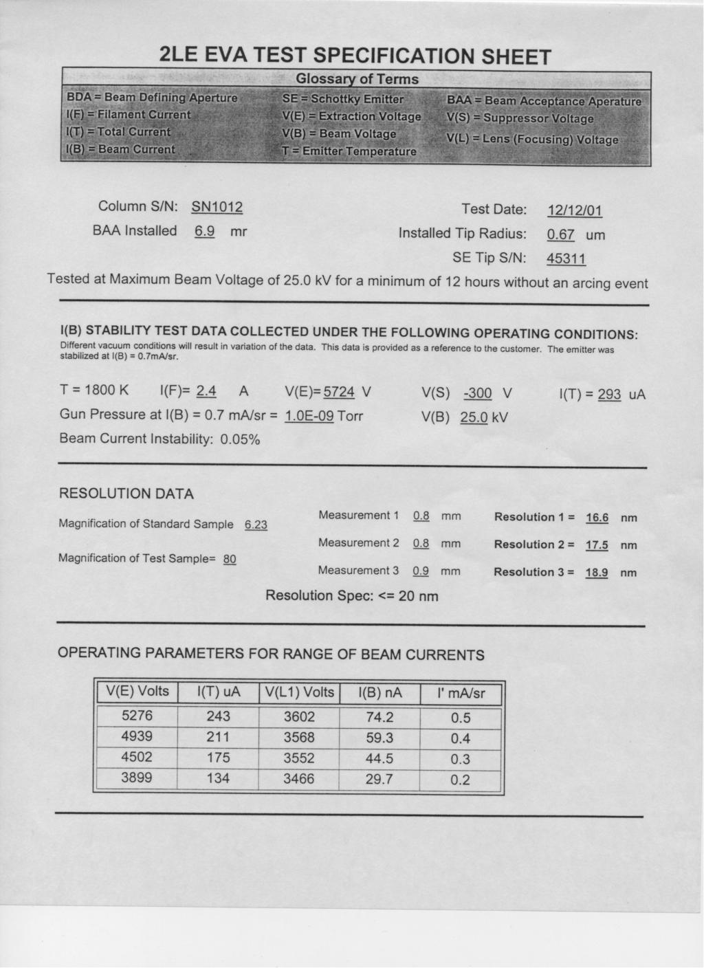
109
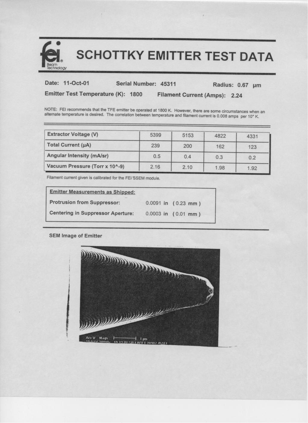
110
NexLine AD Power Line Adaptor INSTALLATION AND OPERATION MANUAL. Westinghouse Security Electronics an ISO 9001 certified company
 NexLie AD 4302 Power Lie Adaptor INSTALLATION AND OPERATION MANUAL Westighouse Security Electroics a ISO 9001 certified compay 5452 Betsy Ross Drive Sata Clara, CA 95054-1184 (408) 727-5170 FAX (408) 727-6707
Manual Industrial air curtain
 Maual Idustrial air curtai Model IdAC2 Versio 6.0 Origial Maual Eglish a INDUSTRIAL AIR CURTAIN... Cotets 1 Itroductio 4 1.1 About this maual 4 1.2 How to read this maual 4 1.3 About the uit 5 1.4 Compoets
Image Intensifier Reference Manual
 Image Itesifier Referece Maual Improvisio, Viscout Cetre II, Uiversity of Warwick Sciece Park, Millbur Hill Road, Covetry. CV4 7HS Tel: 0044 (0) 24 7669 2229 Fax: 0044 (0) 24 7669 0091 e-mail: admi@improvisio.com
Polychrome Devices Reference Manual
 Polychrome Devices Referece Maual Improvisio, Viscout Cetre II, Uiversity of Warwick Sciece Park, Millbur Hill Road, Covetry. CV4 7HS Tel: 0044 (0) 24 7669 2229 Fax: 0044 (0) 24 7669 0091 e-mail: admi@improvisio.com
Manual Comfort Air Curtain
 Maual Comfort Air Curtai Model SesAir Versio 1.0- North America Origial Maual Eglish a COMFORT AIR CURTAIN... Cotets 1 Itroductio 4 1.1 About this maual 4 1.2 How to read this maual 4 1.3 About the uit
2 Specialty Application Photoelectric Sensors
 SMARTEYE STEALTH-UV UVS Aalog/Digital Lumiescece Sesor 2 Specialty Applicatio Photoelectric Sesors 2-93 Specialty Applicatio Photoelectric Sesors 2 SMARTEYE STEALTH-UV UVS Aalog/Digital Lumiescece Sesor
SG Alternatives, LLC 2004 Parts Catalog
 SG Alteratives, LLC 2004 Parts Catalog Iovatio takig form 87B Church Street East Hartford, CT 06108 USA tel.: (860)289-4525 fax: (860)289-3718 email: sgalt3@aol.com March 19, 2004 Dear Customer: We are
FLUID COOLING Industrial BOL Series
 FLUID COOLING Idustrial Series AIR COOLED brazed alumium Costructio Features bar ad Plate Brazed Alumium Core rugged, lightweight, ad compact provides the best heat trasfer per give evelope size while
FHD inch Widescreen LCD Monitor USERGUIDE
 FHD2402 24-ich Widescree LCD Moitor USERGUIDE Cotets Chapter 1: Usig Your Gateway Flat-Pael Moitor.................... 1 Coectig the moitor.................................................... 2 Coectig
8825E/8825R/8830E/8831E SERIES
 FETURES IDC for 0.635mm flat ribbo cable (#30 WG, Straded) Highly reliable 2 poit coectio Low isertio ad withdrawal force Oe-Touch lockig ejector system Pateted ribbo cable cotact desig protects agaist
2 Specialty Application Photoelectric Sensors
 SMARTEYE X-PRO XP10 XP10 -- Extremely High Speed Sesor 2 Specialty Applicatio Photoelectric Sesors 2-119 Specialty Applicatio Photoelectric Sesors 2 SMARTEYE X-PRO XP10 Extremely High Speed (10µs) Photoelectric
Line numbering and synchronization in digital HDTV systems
 Lie umberig ad sychroizatio i digital HDTV systems D. (VURT) I cotrast to aalogue televisio systems where lie umberig is covetioally liked to the vertical sychroizatio, digital televisio offers the possibility
Twin City Fan & Blower
 Twi City Fa & Blower BULLETIN 490 February 2010 MODULAR PLENUM FANS TYPE MPQN Modular Pleum Fas The MPQN offers may of the same advatages of the veerable EPQN pleum fa. The MPQN ca be used as a sigle fa
Manual Air heater. English. Model NOZ2. Version 7.0 Original Manual
 Maual Air heater Model NOZ2 Versio 7.0 Origial Maual Eglish a AIR HEATER... Cotts 1 Itroductio 4 1.1 About this maual 4 1.2 How to read this maual 4 1.3 About the uit 5 1.4 Compots ad accessories 10 1.5
NewBlot PVDF 5X Stripping Buffer
 NewBlot PVDF 5X Strippig Buffer Developed for: Odyssey Family of Imagers Please refer to your maual to cofirm that this protocol is appropriate for the applicatios compatible with your model of Odyssey
Mullard INDUCTOR POT CORE EQUIVALENTS LIST. Mullard Limited, Mullard House, Torrington Place, London Wel 7HD. Telephone:
 Mullard INDUCTOR POT CORE EQUIVALENTS LIST Mullard Limited, Mullard House, Torrigto Place, Lodo Wel 7HD. Telephoe: 01-580 6633 INDUCTOR POT CORE EQUIVALENTS LIST Mullard Limited have bee maufacturig ferrite
Manual RCA-1. Item no fold RailCom display. tams elektronik. n n n
 Maual RCA-1 Item o. 45-02016 1-fold RailCom display Eglish RCA-1 Table of cotets 1. Gettig started...3 2. Safety istructios...5 3. Backgroud iformatio: RailCom...6 4. Operatig mode of the RCA-1...8 5.
Apollo 360 Map Display User s Guide
 Apollo 360 Map Display User s Guide II Morrow Ic. 2345 Turer Road S.E. Salem, Orego 97309 November 1996 P/N 560-0119-00 Apollo 360 Map Display No part of this documet may be reproduced i ay form or by
2 Specialty Application Photoelectric Sensors
 SMARTEYE STEALTH-UV Lumiescet Sesor 2 Specialty Applicatio Photoelectric Sesors 2-87 Specialty Applicatio Photoelectric Sesors 2 SMARTEYE STEALTH-UV The SMARTEYE STEALTH-UV Lumiescece Sesor The SMARTEYE
Chapter 7 Registers and Register Transfers
 Logic ad Computer Desig Fudametals Chapter 7 Registers ad Register Trasfers Part 2 Couters, Register Cells, Buses, & Serial Operatios Charles Kime & Thomas Kamiski 28 Pearso Educatio, Ic (Hyperliks are
PROJECTOR SFX SUFA-X. Properties. Specifications. Application. Tel
 ifo@extgeeratioled.be www.extgeeratioled.be Tel + 32 53 71 09 42 PROJECTOR SFX SUFA-X Properties Lifespa L70 %: > 50.000 hours Eergy savigs up to 65% Boosted istallatio efficiecy thaks to the slimmed-dow
2 Specialty Application Photoelectric Sensors
 SMARTEYE STEALTH-UV Lumiescece Sesor 2 Specialty Applicatio Photoelectric Sesors 2-87 Specialty Applicatio Photoelectric Sesors 2 SMARTEYE STEALTH-UV The SMARTEYE STEALTH-UV Lumiescece Sesor The SMARTEYE
Minimum Span. Maximum Span Setting
 Specificatio Magetic Flowmeters Electrodeless Series 10DX3121 Primary w/ 50CM2000 Coverter Miimum Liquid Coductivity 0.05 µs/cm. Allows may ew harsh process liquids to be measured with a magetic flowmeter.
Working with PlasmaWipe Effects
 Workig with PlasmaWipe Effects Workig with PlasmaWipe Effects PlasmaWipe effects are real-time plug-i effects that use gradiet image bitmaps to create wipes ad segmet effects. There are 64 preset effects,
Our competitive advantages : Solutions for X ray Tubes. X ray emitters. Long lifetime dispensers cathodes n. Electron gun manufacturing capability n
 Solutios for Xray tubes_layout 1 15/12/2014 12:05 Pagia 2 Our competitive advatages : Log lifetime dispesers cathodes Electro gu maufacturig capability High capacity getters for high vacuum requiremets
CAEN Tools for Discovery
 Applicatio Note AN6224 Mout A996 (52 pi cable coector) o a high voltage cable Viareggio 15 September 2017 Itroductio This applicatio ote shows how to assembly the A996 52 Pi HV cable coector desiged to
SMARTEYE ColorWise TM. Specialty Application Photoelectric Sensors. True Color Sensor 2-65
 2 True Color Sesor Specialty Applicatio Photoelectric Sesors 2-65 Specialty Applicatio Photoelectric Sesors 2 The SMARTEYE COLORWISE TM True Color Sesor is the most feature packed color sesor available.
PowerStrip Automatic Cut & Strip Machine
 Automatic Cut & Strip Machie 2 Fully automatic wire processig requires precisio techology tailored to your specific eeds. The combies the utmost i precisio ad performace which cover a ubeatable rage of
ttco.com
 ttco.com 800-237-0946 813-886-4000 The SMARTEYE COLORWISE TM True Color Sesor is the most feature packed color sesor available. Desiged to work as well as a istrumet or spectrometer, this sesor ca solve
Obsolete Product(s) - Obsolete Product(s)
 - Obsolete Product(s)") HIGH VOLTAGE NPN POWER TRANSISTOR FOR HIGH DEFINITION CRT DISPLAYS STATE-OF-THE-ART TECHNOLOGY: DIFFUSED COLLECTOR "ENHANCED GENERATION" EHVS1 WIDER RANGE OF OPTIMUM DRIVE CONDITIONS LESS SENSITIVE TO
HIGH VOLTAGE NPN POWER TRANSISTOR FOR HIGH DEFINITION CRT DISPLAYS STATE-OF-THE-ART TECHNOLOGY: DIFFUSED COLLECTOR "ENHANCED GENERATION" EHVS1 WIDER RANGE OF OPTIMUM DRIVE CONDITIONS LESS SENSITIVE TO
Quality improvement in measurement channel including of ADC under operation conditions
 Quality improvemet i measuremet chael icludig of ADC uder operatio coditios 1 Romuald MASNICKI, 2 Jausz MINDYKOWSKI 1, 2 Gdyia Maritime iversity, ul. Morska 81-83, 81-225 Gdyia, POLAND, tel. (+48 58) 6109
NIIT Logotype YOU MUST NEVER CREATE A NIIT LOGOTYPE THROUGH ANY SOFTWARE OR COMPUTER. THIS LOGO HAS BEEN DRAWN SPECIALLY.
 NIIT Logotype The NIIT logotype is always preseted i a fixed cofiguratio. The desig of the logotype is based o a typeface called Egyptia. The letters N I I T has bee specially desiged ad letter-spaced.
Application Example. HD Hanna. Firewire. Display. Display. Display. Display. Display. Computer DVD. Game Console. RS-232 Control.
 HD Haa Applicatio Example Computer RGBHV for pass through Display RGBHV Display Compoet BNC or RCA (with adapters) Display S-Video Display Composite Video Display DVI-D or HDMI (with adapters) DVD Compoet
Manual WIB Carriage lighting Colour of lighting: warm white. Item no tams elektronik. tams elektronik n n n
 Maual WIB-13.2 Carriage lightig Colour of lightig: warm white Item o. 53-01140 Versio 2016 with OSRAM LEDs Duris E5 tams elektroik tams elektroik Eglish WIB-13.2 Table of cotets 1. Gettig started...2 2.
Sigma 3-30KS Sigma 3-30KHS
 Sigma 3-30KS Sigma 3-30KHS High-speed cetrifuge refrigerated refrigerated/ heatable www.sigma-zetrifuge.de 3 Exceptioal i every respect Sigma is a leadig iteratioal maufacturer of laboratory cetrifuges
EE260: Digital Design, Spring /3/18. n Combinational Logic: n Output depends only on current input. n Require cascading of many structures
 EE260: igital esig, prig 208 4/3/8 EE 260: Itroductio to igital esig equetial Logic Elemets ao Zheg epartmet of Electrical Egieerig Uiversity of Hawaiʻi at Māoa equetial ircuits ombiatioal Logic: Output
DCT 1000 Cable Terminal Installation Manual
 DCT 1000 Cable Termial Istallatio Maual GUIDE CURSOR INFO MENU SELECT BYPASS CHANNEL POWER Graphical symbols ad supplemet warig markig locatios o the bottom of the appliace. This symbol meas that dagerous
BesTrans AOC (Active Optical Cable) Spec and Manual
 Spec and Manual") BesTras AOC (Active Optical Cable) Spec ad Maual A. Techology: BesTras Active Optical Cable (AOC) is a easy-to-use, secure coectio for home video distributio, coferece room presetatio systems, classroom
BesTras AOC (Active Optical Cable) Spec ad Maual A. Techology: BesTras Active Optical Cable (AOC) is a easy-to-use, secure coectio for home video distributio, coferece room presetatio systems, classroom
9311 EN. DIGIFORCE X/Y monitoring. For monitoring press-fit, joining, rivet and caulking operations Series 9311 ±10V DMS.
 DIGIFORCE X/Y moitorig For moitorig press-fit, joiig, rivet ad caulkig operatios Series 9311 ±10V DMS Compatible sesors Piezo Poti Flexible Fieldbus itegratio by PROFIBUS, PROFINET or EtherNet/IP Automatic
Logistics We are here. If you cannot login to MarkUs, me your UTORID and name.
 Logistics We are here 8 Week If you caot logi to arkus, email me your UTORID ad ame. heck lab marks o arkus, if it s recorded wrog, cotact Larry withi a week after the lab. Quiz average: 8% Assembly Laguage
MultiTest Modules. EXFO FTB-3923 Specs Provided by FTB-3920 and FTB-1400
 EXFO FTB-3923 Specs Provided by www.aaatesters.com MultiTest Modules FTB-3920 ad FTB-1400 1625 m light source FasTesT system Retur loss test set Visual fault locator Digital talk set Ultra-High-Power power
DEClaser 3500 Printer Serial Interface Installation Guide
 DEClaser 500 Priter Serial Iterface Istallatio Guide EK-D5PS-IG.A01 Digital Equipmet Corporatio Mayard, Massachusetts Rev # - File Name SERIAL.DOC First Pritig, Jue 1994 Digital Equipmet Corporatio makes
Innovation in the Multi-Screen World. Sirius 800 Series. Multi-format, expandable routing that stands out from the crowd
 Iovatio i the Multi-Scree World Sirius 800 Series Multi-format, expadable routig that stads out from the crowd Sirius 830 A cost effective solutio for Sirius systems 830 up to A 288 cost x 288 effective
Video Cassette Recorder
 3-865-427-12(1) Video Cassette Recorder Operatig Istructios SLV-L49 MX SLV-L52 PA/PC SLV-L59 CL/CS/PR/VZ SLV-X55 MX SLV-L69HF MX SLV-L72HF PA/PC SLV-L79HF CL/CS/VZ SLV-L89HF CL/CS/MX/VZ SLV-X66HF MX 1999
CCTV that s light years ahead
 CCTV that s light years ahead Video multiplexer, digital recorder, dome cotrol, audio ad more? all i oe box! The Digital Sprite 2 ad DS2 Plus are high performace, cost-effective digital CCTV cotrol systems.
Guide to condition reports for domestic electrical installations
 Coditio rpt leaflet A5:codiio rpt leaflet A5 15022012 11:48 Page 1 Guide to coditio reports for domestic electrical istallatios Coditio rpt leaflet A5:codiio rpt leaflet A5 15022012 11:48 Page 2 Courtesy
MJ Mini Gradient Thermal Cycler Instruction Manual
 MJ Mii Gradiet Thermal Cycler Istructio Maual Catalog #PTC 1148 MJ Mii Gradiet Thermal Cycler Istructio Maual Catalog #PTC 1148 Legal Notices Copyright 2009, Bio-Rad Laboratories, Icorporated. All rights
lev-lok Modular Wiring Device System The safer and more efficient solution for modern building electrical systems
 lev-lok Modular Wirig Device System The safer ad more efficiet solutio for moder buildig electrical systems lev-lok The PERFECT productivity solutio for electrical costructio ad maiteace applicatios. SIMPLE
,..,,.,. - z : i,; ;I.,i,,?-.. _.m,vi LJ
 ,..,,.,. - z : i,; ;I.,i,,?-.. _.m,vi 5.. :. 5 LJ Page Itroductio 2 TalkTolO32 Set Keys... 3 Feature Descriptio... 4 Feature Selectio... 5 Feature Programmig... 6 System Programmig Chart... 7 Power Fail
TECHNICAL BULLETIN INTRODUCTION. Bad Boy Luminaire Baseplate Retrofit. Parts, Tools, and Supplies
 TECHICAL BULLETI Product: Bad Boy Spot Luminaire Manufacturer: PRG Subject: Baseplate Retrofit Bulletin o: BAD-014 Date: 01-09-2012 ITRODUCTIO Bad Boy Luminaire Baseplate Retrofit It has been determined
STx. Compact HD/SD COFDM Transmitter. Features. Options. Accessories. Applications
 Compact HD/SD COFDM Trasmitter Features SD ad HD ecodig 200mW RF output power Optimized for size Superior broadcast grade video Wide selectio of video iputs MPEG-4 Part-10/H.264 Two moo audio chaels Very
T-25e, T-39 & T-66. G657 fibres and how to splice them. TA036DO th June 2011
 T-25e, T-39 & T-66 G657 fibres ad how to splice them TA036DO0018-03 10 th Jue 2011 What is G657 fibre? G657 is a ew class of sigle mode fibre which ca be bet more severely the ormal G652 sigle mode without
DEClaser 3500 Printer AppleTalk Installation Guide
 DEClaser 3500 Priter AppleTalk Istallatio Guide EK-D350P-AG.A01 Digital Equipmet Corporatio Mayard, Massachusetts Rev # - File Name APPLE2.DOC First Pritig, Jue 1994 Digital Equipmet Corporatio makes o
Read Only Memory (ROM)
") ECE 545 igital System esig with VHL Lecture A igital Logic Reresher Part A Combiatioal Logic Buildig Blocks Cot. Problem 2 What is a size o ROM with a 4-bit address iput ad a 8-bit data output? What is
ECE 545 igital System esig with VHL Lecture A igital Logic Reresher Part A Combiatioal Logic Buildig Blocks Cot. Problem 2 What is a size o ROM with a 4-bit address iput ad a 8-bit data output? What is
What Does it Take to Build a Complete Test Flow for 3-D IC?
 What Does it Take to Build a Complete Test Flow for 3-D IC? Brio Keller, Bassilios Petrakis, Cadece Thaks to : Sadeep Goel, TSMC EDPS, Moterey, CA April 5-6, 202 Ackowledgemets TSMC Ashok Mehta imec Erik
References and quotations
 CHAPTER 1.8 Refereces ad quotatios Academic writig depeds o the research ad ideas of others, so it is vital to show which sources you have used i your work, i a acceptable maer. This uit explais the format
CSI 2130 Machinery Health Analyzer
 V-2130-012306 Machiery Health Maagemet CSI 2130 Machiery Health Aalyzer Data collectio, vibratio aalysis, aligmet ad balacig i a sigle uit Compact, rugged desig holds up to ay plat eviromet Ituitive operatio
RELIABILITY EVALUATION OF REPAIRABLE COMPLEX SYSTEMS AN ANALYZING FAILURE DATA
 It. J. Mech. Eg. & Rob. Res. 2013 G Gurumahesh et al., 2013 Research Paper ISSN 2278 0149 www.ijmerr.com Vol. 2, No. 1, Jauary 2013 2013 IJMERR. All Rights Reserved RELIABILITY EVALUATION OF REPAIRABLE
Because your pack is worth protecting. Tobacco Biaxially Oriented Polypropylene Films. use our imagination...
 Because your pack is worth protectig Tobacco Biaxially Orieted Polypropylee Films use our imagiatio... Focused o Films Iovia Films has bee supplyig overwrap films to the tobacco idustry for over 45 years.
Tobacco Range. Biaxially Oriented Polypropylene Films and Labels. use our imagination...
 Tobacco Rage Biaxially Orieted Polypropylee Films ad Labels use our imagiatio... Tobacco Rage Leader i Films Iovia Films has bee supplyig overwrap films to the tobacco idustry for over 70 years. We are
Voice Security Selection Guide
 Voice Security Selectio Guide Hoppig Code Voice Iversio with ANI Voice Security Frequecy Domai Split-bad Voice Iversio Double Iversio Radio Ecryptio Rollig Code Voice Scramblers Rollig Double Iversio Frequetly
HD DIGITAL VIDEOCASSETTE RECORDER SRW INSTALLATION MANUAL 1st Edition Serial No and Higher
 HD DIGITAL VIDECASSETTE RECRDER SRW-000 ISTALLATI MAUAL st Editio Serial o. 000 ad Higher ! WARIG This maual is iteded for qualified service persoel oly. To reduce the risk of electric shock, fire or ijury,
Index. LV Series. Multimedia Projectors FULL LINE PRODUCT GUIDE. usa.canon.com/projectors. REALiS LCOS Projectors. WUX10 Mark II D WUX10 Mark II...
 Multimedia Projectors FULL LINE PRODUCT GUIDE Idex REALiS Projectors Mark II D Mark II.... 1 D...... 2 Mark II D Mark II..... 4 Mark II D Mark II..... 5......... 6........ 7......... 8 LV Series LCD Projectors
Design meets function. Laser marking systems Technology, Innovation and Environment
 Desig meets fuctio Laser markig systems Techology, Iovatio ad Eviromet atur Techik Compay Profile page 3 Materials page 12 Fields of Applicatio page 14 OEM-Laser Markers page 16 Workstatios page 32 Optios
Warranty Registration System Help us to serve you better by registering your product for Warranty
 Warraty Registratio System Help us to serve you better by registerig your product for Warraty Web Register at www.oida.com Telephoe Call Cetre No. 0XX-39889000(0XX-STD Code of 5 STAR State Capital) Post
VOCALS SYLLABUS SPECIFICATION Edition
 VOCALS SYLLABUS SPECIFICATION 2016 Editio Vocals Syllabus Specificatio 2016 Editio Rockschool Performace Arts Awards Vocatioal Qualificatios Ackowledgemets Syllabus Vocal specialists: Marti Hibbert ad
tams elektronik Light Computer Anleitung Manual Mode d emploi Handleiding
 Aleitug Maual Mode d emploi Hadleidig Light Computer el ek tro i k Art. 53-02015 - 53-02236 ta m s Für alle Bausätze ud Bausteie der LC-Serie. For all kits ad ready-built modules of the LC series. Pour
Daniel R. Dehaan Three Études For Solo Voice Summer 2010, Chicago
 Daiel R. Dehaa Three Études For Solo Voice Summer 010 Chicago Daiel R. Dehaa Three Études For Solo Voice Summer 010 Chicago Copyright 010 by Daiel R. Dehaa All rights reserved icludig performig rights.
Taking your meetings to the next level is how we re engineering a better world.
 Takig your meetigs to the ext level is how we re egieerig a better world. solutios for BUSINESS Real-time collaboratio i stuig HD A Paasoic HD Visual Commuicatios System lets you simulate ad reap the beefits
apple Service Source Apple Cinema HD Display 23" LCD (ADC) 11 April Apple Computer, Inc. All rights reserved.
 11 April Apple Computer, Inc. All rights reserved.") apple Service Source Apple Cinema HD Display 23" LCD (ADC) 11 April 2003 2003 Apple Computer, Inc. All rights reserved. apple Service Source Take Apart Apple Cinema HD Display 23" LCD (ADC) 2003 Apple
apple Service Source Apple Cinema HD Display 23" LCD (ADC) 11 April 2003 2003 Apple Computer, Inc. All rights reserved. apple Service Source Take Apart Apple Cinema HD Display 23" LCD (ADC) 2003 Apple
Before you submit your application for a speech generating device, we encourage you to take the following steps:
 Public Utility Commissio Residetial Service Protectio Fud Telephoe Assistace Programs 201 High St SE Suite 100 Salem, OR 97301-3612 Mailig Address: PO Box 1088 Salem, OR 97308-1088 1-800-848-4442 TTY:
STEEL BOXES & COVERS
 STEEL BOXES & COVERS FAN SUPPORT BOXES Boxes - 1/2" - 2-1/8" deep Protective metal cover elimiates debris etry ad damage to wire Easy-to-use slide select feature for choosig #8 ad #10 screw holes Eergy
DIGITAL SYSTEM DESIGN
 DIGITAL SYSTEM DESIGN Buildig Block Circuit Rather tha buildig ytem at the gate level, ofte digital ytem are cotructed from higher level, but till baic, buildig block circuit. Multiplexer, decoder, flip-flop,
Internet supported Analysis of MPEG Compressed Newsfeeds
 Proceedigs of the IASTED Iteratioal Coferece Iteret ad Multimedia Systems ad Applicatios October 18-21, 1999 Nassau, Bahamas Iteret supported Aalysis of MPEG Compressed Newsfeeds Guido FALKEMEIER, Gerhard
Perspectives AUTOMATION. As the valve turns By Jim Garrison. The Opportunity to make Misteaks By Doug Aldrich, Ph.D., CFM
 AUTOMATION Perspectives Lessos leared from the field As the valve turs By Jim Garriso The Opportuity to make Misteaks By Doug Aldrich, Ph.D., CFM As the Valve Turs By Jim Garriso AUTOMATION PERSPECTIVES
DSP 18 Sub active subwoofer. user manual
 DSP 18 Sub active subwoofer user manual Musikhaus Thomann Thomann GmbH Hans-Thomann-Straße 1 96138 Burgebrach Germany Telephone: +49 (0) 9546 9223-0 E-mail: info@thomann.de Internet: www.thomann.de 05.11.2018,
Commissioning the TAMUTRAP RFQ cooler/buncher. E. Bennett, R. Burch, B. Fenker, M. Mehlman, D. Melconian, and P.D. Shidling
 Commissioning the TAMUTRAP RFQ cooler/buncher E. Bennett, R. Burch, B. Fenker, M. Mehlman, D. Melconian, and P.D. Shidling In order to efficiently load ions into a Penning trap, the ion beam should be
PROBABILITY AND STATISTICS Vol. I - Ergodic Properties of Stationary, Markov, and Regenerative Processes - Karl Grill
 PROBABILITY AND STATISTICS Vol. I Ergodic Properties of Statioary, Markov, ad Regeerative Processes Karl Grill ERGODIC PROPERTIES OF STATIONARY, MARKOV, AND REGENERATIVE PROCESSES Karl Grill Istitut für
Motivation. Analysis-and-manipulation approach to pitch and duration of musical instrument sounds without distorting timbral characteristics
 Aalysis-ad-maipulatio approach to pitch ad duratio of musical istrumet souds without distortig timbral characteristics Takehiro Abe Katsutoshi Itoyama Kazuyoshi Yoshii Kazuori Komatai Tetsuya Ogata Hiroshi
Accessories FOR HELIAX PRODUCTS. P r o d u c t S E L E C T I O N G U I D E
 Accessories FOR HELIAX PRODUCTS P r o d u c t S E L E C T I O N G U I D E 2 0 0 7 Table of Cotets Itroductio Cable Istallatio Accessories Cable Hoistig ad Attachmets... 8 Weatherproofig... 19 Cable Etry...
COHERENCE ONE PREAMPLIFIER
 COHERENCE ONE PREAMPLIFIER OWNER S MANUAL TABLE OF CONTENTS Introduction Features Unpacking Instructions Installation Phono Cartridge Loading Basic Troubleshooting Technical Specifications Introduction
CRAYON. The crayons for the digital generation
 The crayos for the digital geeratio ABOUT BENEFITS is a iteractive multi-touch table desiged specifically for kids. With a appealig ad fu desig, comes complete with eight games that ecourage childre to
apple Service Source Apple Studio Display 17" LCD (ADC) Updated 6 Decenber Apple Computer, Inc. All rights reserved.
 Updated 6 Decenber Apple Computer, Inc. All rights reserved.") apple Service Source Apple Studio Display 17" LCD (ADC) Updated 6 Decenber 2004 2003 Apple Computer, Inc. All rights reserved. apple Service Source Take Apart Apple Studio Display 17" LCD (ADC) 2003 Apple
apple Service Source Apple Studio Display 17" LCD (ADC) Updated 6 Decenber 2004 2003 Apple Computer, Inc. All rights reserved. apple Service Source Take Apart Apple Studio Display 17" LCD (ADC) 2003 Apple
INSTALLATION INSTRUCTIONS
 LIGHTGUARD 350-20-WTC SEALED FIBER OPTIC CLOSURE VIEW ONLINE TABLE OF CONTENTS: GENERAL...2 SPECIFICATIONS...2 PACKAGE CONTENTS...3 PACKAGE CONTENTS: ACCESSORIES...3 RECOMMENDED TOOLS...3 ADD-ON COMPONENTS...4
PIANO SYLLABUS SPECIFICATION. Also suitable for Keyboards Edition
 PIANO SYLLABUS SPECIFICATION Also suitable for Keyboards 2016 Editio Piao Syllabus Specificatio 2016 Editio Rockschool Performace Arts Awards Vocatioal Qualificatios Ackowledgemets Syllabus Syllabus writte
Background Manuscript Music Data Results... sort of Acknowledgments. Suite, Suite Phylogenetics. Michael Charleston and Zoltán Szabó
 Suite, Suite Phylogeetics /5 Suite, Suite Phylogeetics Michael Charlesto ad Zoltá Szabó michael.charlesto@sydey.edu.au November 5th, 20 Suite, Suite Phylogeetics 2/5 S Bach oha Sebastia Bach was bor i
Energy-Efficient FPGA-Based Parallel Quasi-Stochastic Computing
 Article Eergy-Efficiet FPGA-Based Parallel Quasi-Stochastic Computig Ramu Seva, Prashathi Metku * ad Misu Choi Departmet of Computer Egieerig, Missouri Uiversity of Sciece & Techology, 4 Emerso Electric
INSTALLATION SOLUTIONS 2012
 istallatio:iovatio INSTALLATION SOLUTIONS 2012 AUDIO CONNECTIVITY CONTROL BRACKETRY DESIGNED BY INSTALLERS FOR INSTALLERS www.visioaudiovisual.com WINNER Maufacturer of the Year 2006 WINNER Audio Product
The Communication Method of Distance Education System and Sound Control Characteristics
 36 IJCSNS Iteratioal Joural of Computer Sciece ad Network Security, VO.6 No.7A, July 006 The Commuicatio ethod of Distace Educatio System ad Soud Cotrol Characteristics aabu Ishihara, Departmet of Electrical
Achat 115 Sub A active subwoofer. user manual
 Achat 115 Sub A active subwoofer user manual Musikhaus Thomann Thomann GmbH Hans-Thomann-Straße 1 96138 Burgebrach Deutschland Telephone: +49 (0) 9546 9223-0 E-mail: info@thomann.de Internet: www.thomann.de
Math of Projections:Overview. Perspective Viewing. Perspective Projections. Perspective Projections. Math of perspective projection
 Math of Projectios:Overview Math of perspective projectio, stadard cofiguratio OpeGL perspective projectios Math of orthographic projectio OpeGL orthographic projectios Viewport trasformatios ad settig
Forces: Calculating Them, and Using Them Shobhana Narasimhan JNCASR, Bangalore, India
 Forces: Calculatig Them, ad Usig Them Shobhaa Narasimha JNCASR, Bagalore, Idia shobhaa@jcasr.ac.i Shobhaa Narasimha, JNCASR 1 Outlie Forces ad the Hellma-Feyma Theorem Stress Techiques for miimizig a fuctio
OPERATION NOTES FOR PSIDEX AUDIO PGP-1A PRE-AMPLIFIER DESCRIPTION INSTALLATION
 OPERATION NOTES FOR PSIDEX AUDIO PGP-1A PRE-AMPLIFIER DESCRIPTION The Psidex Audio Laboratory PGP- 1A is a vacuum tube based microphone preamp and program line amplifier designed to provide solid, robust
Australian Journal of Basic and Applied Sciences
 Australia Joural of Basic ad Applied Scieces, 8(11) Special 2014, Pages: 16-22 AENSI Jourals Australia Joural of Basic ad Applied Scieces ISSN:1991-8178 Joural home page: www.abasweb.com Explorig the Hammig
MASTR II BASE STATION 12/24V POWER SUPPLY 19A149979P1-120 VOLT/60 Hz 19A149979P2-230 VOLT/50 Hz
 Mobile Communications MASTR II BASE STATION 12/24V POWER SUPPLY 19A149979P1-120 VOLT/60 Hz 19A149979P2-230 VOLT/50 Hz CAUTION THESE SERVICING INSTRUCTIONS ARE FOR USE BY QUALI- FIED PERSONNEL ONLY. TO
THE Internet of Things (IoT) is likely to be incorporated
 is likely to be incorporated") This is the author's versio of a article that has bee published i this oural. Chages were made to this versio by the publisher prior to publicatio. IEEE INTERNET OF THINGS JOURNAL, VOL. 5, NO. 1, FEBRUARY
This is the author's versio of a article that has bee published i this oural. Chages were made to this versio by the publisher prior to publicatio. IEEE INTERNET OF THINGS JOURNAL, VOL. 5, NO. 1, FEBRUARY
Music Scope Headphones: Natural User Interface for Selection of Music
 Music Scope Headphoes: Natural User Iterface for Selectio of Music Masatoshi Hamaaka Presto, Japa Sciece ad Techology Agecy A.I.S.T. Mbox 604 1-1-1 Umezoo, Tsukuba, Ibaraki, 305-8568 Japa m.hamaaka@aist.go.jp
Quick Start. RSHS1000 Series Handheld Digital Oscilloscope
 Quick Start RSHS1000 Series Handheld Digital Oscilloscope General Safety Summary Carefully read the following safety precautions to avoid personal injury and prevent damage to the instrument or any products
Gigabit Multi-mode SX to Single Mode LX Converter. User s Manual NGF-728 Series. Warning COPYRIGHT
 COPYRIGHT Gigabit Multi-mode SX to Single Mode LX Converter User s Manual NGF-728 Series All rights reserved. No part of this publication may be reproduced, stored in a retrieval system, or transmitted
SATRI AMPLIFIER AMP-51R. Owner s Manual
 SATRI AMPLIFIER AMP-51R Owner s Manual contents SAFETY INSTRUCTIONS 4 INTRODUCTION 6 OVERVIEW (FRONT PANEL) 8 OVERVIEW (REAR PANEL) 9 OVERVIEW (REMOTE CONTROL) 1 1 OPERATION 12 TROUBLESHOOTING 13 SPECIFICATION