Counters. ENT 263 Digital Electronics
|
|
|
- Asher Chandler
- 5 years ago
- Views:
Transcription
1 Counters ENT 263 Digital Electronics
2 Objectives Describe the difference between an asynchronous and a synchronous counter Analyze counter timing diagram Analyze counter circuits Determine the sequence of a counter and more
3 Counting in Binary The next bit changes on every fourth number LSB changes on every number. The next bit changes on every other number. LSB MSB
4 Asynchronous Counter Operation In an asynchronous counter, the clock is applied only to the first stage. Subsequent stages derive the clock from the previous stage. Asynchronous binary counter 2-bit asynchronous binary counter 3-bit asynchronous binary counter 4-bit asynchronous binary counter Asynchronous decade counter

5 2-bit asynchronous binary counter

6 3-bit asynchronous binary counter
7 4-bit asynchronous binary counter

8 Asynchronous decade counter
9
10 Propagation Delay
11 Synchronous Counter Operation Clock signal supplied to all Flip-flops Synchronous binary counters 2-bit counter 3-bit counter 4-bit counter Synchronous BCD decade counter
12 2-bit synchronous binary counter 0 1 0

13 3-bit synchronous binary counter
14 ND gate utputs is IGH 4-bit synchronous binary counter


15 Synchronous BCD decade counter

16 Up/Down Synchronous Counters 3-bit up/down synchronous counter Up/down decade synchronous counter

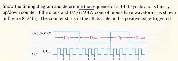
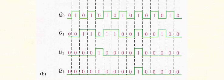
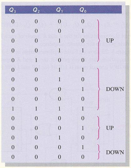
17 3-Bit Up/Down Synchronous Counter
18
19

20 Up/Down Decade Synchronous Counter

21 Design of Synchronous Counters General clocked sequential circuit Next State Present State
22 Steps used in the design of sequential circuit 1. Specify the counter sequence and draw a state diagram 2. Derive a next-state table from the state diagram 3. Develop a transition table showing the flip-flop inputs required for each transition. The transition table is always the same for a given type of flip-flop 4. Transfer the J and K states from the transition table to Karnaugh maps. There is a Karnaugh map for each input of each flip-flop. 5. Group the Karnaugh map cells to generate and derive the logic expression for each flip-flop input. 6. Implement the expressions with combinational logic, and combine with the flip-flops to create the counter.

23 State diagram for a 3-bit Gray code counter
24 Next-state table for a 3-bit Gray code counter. Present State Next State Q 2 Q 1 Q 0 Q 2 Q 1 Q
25 Transition Table for a J-K flip-flop Output Transitions Flip-flop Inputs Q N Q N+1 J K X X 1 0 X X 0 Q N : present state Q N+1: next state X: Don t care

26 Example of the Mapping Procedure
27

28 Three-bit Gray code counter.
29 Example: Design a counter with the irregular binary count sequence as shown in the state diagram. Use J-K flip-flops
30 Next-state table Present State Next State Q 2 Q 1 Q 0 Q 2 Q 1 Q
31 Transition Table for a J-K flip-flop Output Transitions Flip-flop Inputs Q N Q N+1 J K X X 1 0 X X 0
32 K-MAP

33 THE COUNTER CIRCUIT

34 Example : State diagram for a 3-bit up/down Gray code counter.
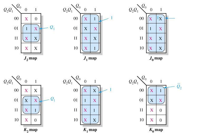
35 J and K maps for Table The UP/DOWN control input, Y, is treated as a fourth variable.
36 Three-bit up/down Gray code counter.


37 CASCADE COUNTERS Two cascaded counters (all J and K inputs are HIGH).
38 A modulus-100 counter using two cascaded decade counters.
39 Three cascaded decade counters forming a divide-by frequency divider with intermediate divide- by- 10 and divide-by-100 outputs.
 the overall modulus for the 4 counter configuration is 10 x 4 x 7 x 5 =")
40 Example: Determine the overall modulus of the two cascaded counter for (a) and (b) For (a) the overall modulus for the 3 counter configuration is 8 x 12 x 16 = 1536 for (b) the overall modulus for the 4 counter configuration is 10 x 4 x 7 x 5 = 1400
41 A divide-by-100 counter using two 74LS160 decade counters.
42 Cascaded Counters with Truncated Sequences A divide-by-40,000 counter using 74HC161 4-bit binary counters. Note that each of the parallel data inputs is shown in binary order (the right-most bit D0 is the LSB in each counter) = 65,536 65,536 40,000 = 25,536 63C0 16
43 COUNTER DECODING * To determine when the counter is in a certain states in its sequence by using decoders or logic gates. Decoding of state 6 (110). Active High Decoding
44 Example: Implement the decoding of binary state 2 and binary state 7 of a 3-bit synchronous counter. Show the entire counter timing diagram and the output waveforms of the decoding gates. 2 = 010 (Q 2 Q 1 Q 0 ) 7 = 111 (Q 2 Q 1 Q 0 )
45 A 3-bit counter with active-high decoding of count 2 and count 7.
46 Decoding Glitches A basic decade (BCD) counter and decoder.

47 Outputs with glitches from the previous decoder. Glitch widths are exaggerated for illustration and are usually only a few nanoseconds wide.
48 The basic decade counter and decoder with strobing to eliminate glitches. Strobing: To enable the decoded outputs at a time after the glitches have had time to disappear. Using LOW level of active- HIGH clock to enable the decoder.

49 Strobed decoder outputs for the circuit
50 Counter Applications

51 Simplified logic diagram for a 12-hour digital clock.
52 Logic diagram of typical divide-by-60 counter using 74LS160A synchronous decade counters. Note that the outputs are in binary order (the right-most bit is the LSB).
53 Logic diagram for hours counter and decoders. Note that on the counter inputs and outputs, the right-most bit is the LSB.

54 Functional block diagram for parking garage control.
55 Logic diagram for modulus-100 up/down counter for automobile parking control.
56 Parallel-to-serial data conversion logic.

57 Example of parallel-to-serial conversion timing for the previous circuit
58 Thank You Intan berlian walaupun di atas lumpur dia pasti akan bercahaya, akan tetapi najis ayam walaupun diletakkan di atas meja tetap akan berbau busuk jua - Cendikiawan
EKT 121/4 ELEKTRONIK DIGIT 1
 EKT 2/4 ELEKTRONIK DIGIT Kolej Universiti Kejuruteraan Utara Malaysia Sequential Logic Circuits - COUNTERS - LATCHES (review) S-R R Latch S-R R Latch Active-LOW input INPUTS OUTPUTS S R Q Q COMMENTS Q
Digital Fundamentals: A Systems Approach
 Digital Fundamentals: A Systems Approach Counters Chapter 8 A System: Digital Clock Digital Clock: Counter Logic Diagram Digital Clock: Hours Counter & Decoders Finite State Machines Moore machine: One
ASYNCHRONOUS COUNTER CIRCUITS
 ASYNCHRONOUS COUNTER CIRCUITS Asynchronous counters do not have a common clock that controls all the Hipflop stages. The control clock is input into the first stage, or the LSB stage of the counter. The
2. Counter Stages or Bits output bits least significant bit (LSB) most significant bit (MSB) 3. Frequency Division 4. Asynchronous Counters
 most significant bit (MSB) 3. Frequency Division 4. Asynchronous Counters") 2. Counter Stages or Bits The number of output bits of a counter is equal to the flip-flop stages of the counter. A MOD-2 n counter requires n stages or flip-flops in order to produce a count sequence
2. Counter Stages or Bits The number of output bits of a counter is equal to the flip-flop stages of the counter. A MOD-2 n counter requires n stages or flip-flops in order to produce a count sequence
Experiment 8 Introduction to Latches and Flip-Flops and registers
 Experiment 8 Introduction to Latches and Flip-Flops and registers Introduction: The logic circuits that have been used until now were combinational logic circuits since the output of the device depends
CHAPTER 6 COUNTERS & REGISTERS
 CHAPTER 6 COUNTERS & REGISTERS 6.1 Asynchronous Counter 6.2 Synchronous Counter 6.3 State Machine 6.4 Basic Shift Register 6.5 Serial In/Serial Out Shift Register 6.6 Serial In/Parallel Out Shift Register
Asynchronous (Ripple) Counters
 Counters") Circuits for counting events are frequently used in computers and other digital systems. Since a counter circuit must remember its past states, it has to possess memory. The chapter about flip-flops introduced
Circuits for counting events are frequently used in computers and other digital systems. Since a counter circuit must remember its past states, it has to possess memory. The chapter about flip-flops introduced
Review of digital electronics. Storage units Sequential circuits Counters Shifters
 Review of digital electronics Storage units Sequential circuits ounters Shifters ounting in Binary A counter can form the same pattern of 0 s and 1 s with logic levels. The first stage in the counter represents
Counters
 Counters A counter is the most versatile and useful subsystems in the digital system. A counter driven by a clock can be used to count the number of clock cycles. Since clock pulses occur at known intervals,
Logic and Computer Design Fundamentals. Chapter 7. Registers and Counters
 Logic and Computer Design Fundamentals Chapter 7 Registers and Counters Registers Register a collection of binary storage elements In theory, a register is sequential logic which can be defined by a state
Vignana Bharathi Institute of Technology UNIT 4 DLD
 DLD UNIT IV Synchronous Sequential Circuits, Latches, Flip-flops, analysis of clocked sequential circuits, Registers, Shift registers, Ripple counters, Synchronous counters, other counters. Asynchronous
Chapter 7 Counters and Registers
 Chapter 7 Counters and Registers Chapter 7 Objectives Selected areas covered in this chapter: Operation & characteristics of synchronous and asynchronous counters. Analyzing and evaluating various types
Registers and Counters
 Registers and Counters Clocked sequential circuit = F/Fs and combinational gates Register Group of flip-flops (share a common clock and capable of storing one bit of information) Consist of a group of
Sequential Logic Counters and Registers
 Sequential Logic ounters and Registers ounters Introduction: ounters Asynchronous (Ripple) ounters Asynchronous ounters with MOD number < 2 n Asynchronous Down ounters ascading Asynchronous ounters svbitec.wordpress.com
Chapter 3 Unit Combinational
 EE 200: Digital Logic Circuit Design Dr Radwan E Abdel-Aal, COE Logic and Computer Design Fundamentals Chapter 3 Unit Combinational 5 Registers Logic and Design Counters Part Implementation Technology
Registers and Counters
 Registers and Counters Clocked sequential circuit = F/Fs and combinational gates Register Group of flip-flops (share a common clock and capable of storing one bit of information) Consist of a group of
Chapter 9. Design of Counters
 Chapter 9 Design of Counters 9.0 Introduction Counter is another class of sequential circuits that tally a series of input pulses which may be regular or irregular in nature. Counter can be divided into
Final Exam review: chapter 4 and 5. Supplement 3 and 4
 Final Exam review: chapter 4 and 5. Supplement 3 and 4 1. A new type of synchronous flip-flop has the following characteristic table. Find the corresponding excitation table with don t cares used as much
UNIT-3: SEQUENTIAL LOGIC CIRCUITS
 UNIT-3: SEQUENTIAL LOGIC CIRCUITS STRUCTURE 3. Objectives 3. Introduction 3.2 Sequential Logic Circuits 3.2. NAND Latch 3.2.2 RS Flip-Flop 3.2.3 D Flip-Flop 3.2.4 JK Flip-Flop 3.2.5 Edge Triggered RS Flip-Flop
RS flip-flop using NOR gate
 RS flip-flop using NOR gate Triggering and triggering methods Triggering : Applying train of pulses, to set or reset the memory cell is known as Triggering. Triggering methods:- There are basically two
Figure 30.1a Timing diagram of the divide by 60 minutes/seconds counter
 Digital Clock The timing diagram figure 30.1a shows the time interval t 6 to t 11 and t 19 to t 21. At time interval t 9 the units counter counts to 1001 (9) which is the terminal count of the 74x160 decade
Switching Theory And Logic Design UNIT-IV SEQUENTIAL LOGIC CIRCUITS
 Switching Theory And Logic Design UNIT-IV SEQUENTIAL LOGIC CIRCUITS Sequential circuits Classification of sequential circuits: Sequential circuits may be classified as two types. 1. Synchronous sequential
Counter dan Register
 Counter dan Register Introduction Circuits for counting events are frequently used in computers and other digital systems. Since a counter circuit must remember its past states, it has to possess memory.
Synchronous sequential circuits
 8.6.5 Synchronous sequential Table of content. Combinational circuit design. Elementary combinatorial for data transmission. Memory structures 4. Programmable logic devices 5. Algorithmic minimization
Chapter 6. Flip-Flops and Simple Flip-Flop Applications
 Chapter 6 Flip-Flops and Simple Flip-Flop Applications Basic bistable element It is a circuit having two stable conditions (states). It can be used to store binary symbols. J. C. Huang, 2004 Digital Logic
DIGITAL SYSTEM FUNDAMENTALS (ECE421) DIGITAL ELECTRONICS FUNDAMENTAL (ECE422) COUNTERS
 DIGITAL ELECTRONICS FUNDAMENTAL (ECE422) COUNTERS") COURSE / CODE DIGITAL SYSTEM FUNDAMENTALS (ECE421) DIGITAL ELECTRONICS FUNDAMENTAL (ECE422) COUNTERS One common requirement in digital circuits is counting, both forward and backward. Digital clocks and
COURSE / CODE DIGITAL SYSTEM FUNDAMENTALS (ECE421) DIGITAL ELECTRONICS FUNDAMENTAL (ECE422) COUNTERS One common requirement in digital circuits is counting, both forward and backward. Digital clocks and
Digital Systems Laboratory 3 Counters & Registers Time 4 hours
 Digital Systems Laboratory 3 Counters & Registers Time 4 hours Aim: To investigate the counters and registers constructed from flip-flops. Introduction: In the previous module, you have learnt D, S-R,
CSE Latches and Flip-flops Dr. Izadi. NOR gate property: A B Z Cross coupled NOR gates: S M S R Q M
 CSE-4523 Latches and Flip-flops Dr. Izadi NOR gate property: A B Z A B Z Cross coupled NOR gates: S M S R M R S M R S R S R M S S M R R S ' Gate R Gate S R S G R S R (t+) S G R Flip_flops:. S-R flip-flop
Module -5 Sequential Logic Design
 Module -5 Sequential Logic Design 5.1. Motivation: In digital circuit theory, sequential logic is a type of logic circuit whose output depends not only on the present value of its input signals but on
RS flip-flop using NOR gate
 RS flip-flop using NOR gate Triggering and triggering methods Triggering : Applying train of pulses, to set or reset the memory cell is known as Triggering. Triggering methods:- There are basically two
Asynchronous counters
 Asynchronous counters In the previous section, we saw a circuit using one J-K flip-flop that counted backward in a two-bit binary sequence, from 11 to 10 to 01 to 00. Since it would be desirable to have
Chapter 9 Counters. Clock Edge Output Q 2 Q 1 Q
 hapter 9 ounters 9. Introduction ounters are devices which have a LOK input and produce n outputs. ounters consist of flip-flops connected together in specific ways such that on each clock edge the output
MUHAMMAD NAEEM LATIF MCS 3 RD SEMESTER KHANEWAL
 1. A stage in a shift register consists of (a) a latch (b) a flip-flop (c) a byte of storage (d) from bits of storage 2. To serially shift a byte of data into a shift register, there must be (a) one click
Chapter 4. Logic Design
 Chapter 4 Logic Design 4.1 Introduction. In previous Chapter we studied gates and combinational circuits, which made by gates (AND, OR, NOT etc.). That can be represented by circuit diagram, truth table
SEQUENTIAL LOGIC. Satish Chandra Assistant Professor Department of Physics P P N College, Kanpur
 SEQUENTIAL LOGIC Satish Chandra Assistant Professor Department of Physics P P N College, Kanpur www.satish0402.weebly.com OSCILLATORS Oscillators is an amplifier which derives its input from output. Oscillators
1. Convert the decimal number to binary, octal, and hexadecimal.
 1. Convert the decimal number 435.64 to binary, octal, and hexadecimal. 2. Part A. Convert the circuit below into NAND gates. Insert or remove inverters as necessary. Part B. What is the propagation delay
INC 253 Digital and electronics laboratory I
 INC 253 Digital and electronics laboratory I Laboratory 9 Sequential Circuit Author: ID Co-Authors: 1. ID 2. ID 3. ID Experiment Date: Report received Date: Comments For Instructor Full Marks Pre lab 10
CHAPTER 4: Logic Circuits
 CHAPTER 4: Logic Circuits II. Sequential Circuits Combinational circuits o The outputs depend only on the current input values o It uses only logic gates, decoders, multiplexers, ALUs Sequential circuits
Lecture 8: Sequential Logic
 Lecture 8: Sequential Logic Last lecture discussed how we can use digital electronics to do combinatorial logic we designed circuits that gave an immediate output when presented with a given set of inputs
UNIVERSITI TEKNOLOGI MALAYSIA
 SULIT Faculty of Computing UNIVERSITI TEKNOLOGI MALAYSIA FINAL EXAMINATION SEMESTER I, 2016 / 2017 SUBJECT CODE : SUBJECT NAME : SECTION : TIME : DATE/DAY : VENUES : INSTRUCTIONS : Answer all questions
Contents Circuits... 1
 Contents Circuits... 1 Categories of Circuits... 1 Description of the operations of circuits... 2 Classification of Combinational Logic... 2 1. Adder... 3 2. Decoder:... 3 Memory Address Decoder... 5 Encoder...
Digital Logic Design ENEE x. Lecture 19
 Digital Logic Design ENEE 244-010x Lecture 19 Announcements Homework 8 due on Monday, 11/23. Agenda Last time: Timing Considerations (6.3) Master-Slave Flip-Flops (6.4) This time: Edge-Triggered Flip-Flops
1. a) For the circuit shown in figure 1.1, draw a truth table showing the output Q for all combinations of inputs A, B and C. [4] Figure 1.
![1. a) For the circuit shown in figure 1.1, draw a truth table showing the output Q for all combinations of inputs A, B and C. [4] Figure 1.](/thumbs/88/117492374.jpg "1. a) For the circuit shown in figure 1.1, draw a truth table showing the output Q for all combinations of inputs A, B and C. [4] Figure 1.") [Question 1 is compulsory] 1. a) For the circuit shown in figure 1.1, draw a truth table showing the output Q for all combinations of inputs A, B and C. Figure 1.1 b) Minimize the following Boolean functions:
[Question 1 is compulsory] 1. a) For the circuit shown in figure 1.1, draw a truth table showing the output Q for all combinations of inputs A, B and C. Figure 1.1 b) Minimize the following Boolean functions:
Logic Design. Flip Flops, Registers and Counters
 Logic Design Flip Flops, Registers and Counters Introduction Combinational circuits: value of each output depends only on the values of inputs Sequential Circuits: values of outputs depend on inputs and
Scanned by CamScanner
 NAVEEN RAJA VELCHURI DSD & Digital IC Applications Example: 2-bit asynchronous up counter: The 2-bit Asynchronous counter requires two flip-flops. Both flip-flop inputs are connected to logic 1, and initially
Universal Asynchronous Receiver- Transmitter (UART)
") Universal Asynchronous Receiver- Transmitter (UART) (UART) Block Diagram Four-Bit Bidirectional Shift Register Shift Register Counters Shift registers can form useful counters by recirculating a pattern
Universal Asynchronous Receiver- Transmitter (UART) (UART) Block Diagram Four-Bit Bidirectional Shift Register Shift Register Counters Shift registers can form useful counters by recirculating a pattern
ECE 263 Digital Systems, Fall 2015
 ECE 263 Digital Systems, Fall 2015 REVIEW: FINALS MEMORY ROM, PROM, EPROM, EEPROM, FLASH RAM, DRAM, SRAM Design of a memory cell 1. Draw circuits and write 2 differences and 2 similarities between DRAM
THE KENYA POLYTECHNIC
 THE KENYA POLYTECHNIC ELECTRICAL/ELECTRONICS ENGINEERING DEPARTMENT HIGHER DIPLOMA IN ELECTRICAL ENGINEERING END OF YEAR II EXAMINATIONS NOVEMBER 006 DIGITAL ELECTRONICS 3 HOURS INSTRUCTIONS TO CANDIDATES:
VTU NOTES QUESTION PAPERS NEWS RESULTS FORUMS Registers
 Registers Registers are a very important digital building block. A data register is used to store binary information appearing at the output of an encoding matrix.shift registers are a type of sequential
Bachelor Level/ First Year/ Second Semester/ Science Full Marks: 60 Computer Science and Information Technology (CSc. 151) Pass Marks: 24
 Pass Marks: 24") 2065 Computer Science and Information Technology (CSc. 151) Pass Marks: 24 Time: 3 hours. Candidates are required to give their answers in their own words as for as practicable. Attempt any TWO questions:
2065 Computer Science and Information Technology (CSc. 151) Pass Marks: 24 Time: 3 hours. Candidates are required to give their answers in their own words as for as practicable. Attempt any TWO questions:
IT T35 Digital system desigm y - ii /s - iii
 UNIT - III Sequential Logic I Sequential circuits: latches flip flops analysis of clocked sequential circuits state reduction and assignments Registers and Counters: Registers shift registers ripple counters
UNIT III. Combinational Circuit- Block Diagram. Sequential Circuit- Block Diagram
 UNIT III INTRODUCTION In combinational logic circuits, the outputs at any instant of time depend only on the input signals present at that time. For a change in input, the output occurs immediately. Combinational
MC9211 Computer Organization
 MC9211 Computer Organization Unit 2 : Combinational and Sequential Circuits Lesson2 : Sequential Circuits (KSB) (MCA) (2009-12/ODD) (2009-10/1 A&B) Coverage Lesson2 Outlines the formal procedures for the
DIGITAL ELECTRONICS MCQs
 DIGITAL ELECTRONICS MCQs 1. A 8-bit serial in / parallel out shift register contains the value 8, clock signal(s) will be required to shift the value completely out of the register. A. 1 B. 2 C. 4 D. 8
Flip-Flops and Related Devices. Wen-Hung Liao, Ph.D. 4/11/2001
 Flip-Flops and Related Devices Wen-Hung Liao, Ph.D. 4/11/2001 Objectives Recognize the various IEEE/ANSI flip-flop symbols. Use state transition diagrams to describe counter operation. Use flip-flops in
NH 67, Karur Trichy Highways, Puliyur C.F, Karur District UNIT-III SEQUENTIAL CIRCUITS
 NH 67, Karur Trichy Highways, Puliyur C.F, 639 114 Karur District DEPARTMENT OF ELETRONICS AND COMMUNICATION ENGINEERING COURSE NOTES SUBJECT: DIGITAL ELECTRONICS CLASS: II YEAR ECE SUBJECT CODE: EC2203
Sri Vidya College of Engineering And Technology. Virudhunagar Department of Electrical and Electronics Engineering
 Sri Vidya College of Engineering And Technology Virudhunagar 626 005 Department of Electrical and Electronics Engineering Year/ Semester/ Class : II/ III/ EEE Academic Year: 2017-2018 Subject Code/ Name:
EET2411 DIGITAL ELECTRONICS
 5-8 Clocked D Flip-FlopFlop One data input. The output changes to the value of the input at either the positive going or negative going clock trigger. May be implemented with a J-K FF by tying the J input
VU Mobile Powered by S NO Group
 Question No: 1 ( Marks: 1 ) - Please choose one A 8-bit serial in / parallel out shift register contains the value 8, clock signal(s) will be required to shift the value completely out of the register.
Serial In/Serial Left/Serial Out Operation
 Shift Registers The need to storage binary data was discussed earlier. In digital circuits multi-bit data has to be stored temporarily until it is processed. A flip-flop is able to store a single binary
Advanced Devices. Registers Counters Multiplexers Decoders Adders. CSC258 Lecture Slides Steve Engels, 2006 Slide 1 of 20
 Advanced Devices Using a combination of gates and flip-flops, we can construct more sophisticated logical devices. These devices, while more complex, are still considered fundamental to basic logic design.
CHAPTER 4: Logic Circuits
 CHAPTER 4: Logic Circuits II. Sequential Circuits Combinational circuits o The outputs depend only on the current input values o It uses only logic gates, decoders, multiplexers, ALUs Sequential circuits
MODULE 3. Combinational & Sequential logic
 MODULE 3 Combinational & Sequential logic Combinational Logic Introduction Logic circuit may be classified into two categories. Combinational logic circuits 2. Sequential logic circuits A combinational
MODEL QUESTIONS WITH ANSWERS THIRD SEMESTER B.TECH DEGREE EXAMINATION DECEMBER CS 203: Switching Theory and Logic Design. Time: 3 Hrs Marks: 100
 MODEL QUESTIONS WITH ANSWERS THIRD SEMESTER B.TECH DEGREE EXAMINATION DECEMBER 2016 CS 203: Switching Theory and Logic Design Time: 3 Hrs Marks: 100 PART A ( Answer All Questions Each carries 3 Marks )
Chapter 11 State Machine Design
 Chapter State Machine Design CHAPTER OBJECTIVES Upon successful completion of this chapter, you will be able to: Describe the components of a state machine. Distinguish between Moore and Mealy implementations
Flip-Flops and Sequential Circuit Design
 Flip-Flops and Sequential Circuit Design ECE 52 Summer 29 Reading ssignment Brown and Vranesic 7 Flip-Flops, Registers, Counters and a Simple Processor 7.5 T Flip-Flop 7.5. Configurable Flip-Flops 7.6
YEDITEPE UNIVERSITY DEPARTMENT OF COMPUTER ENGINEERING. EXPERIMENT VIII: FLIP-FLOPS, COUNTERS 2014 Fall
 YEDITEPE UNIVERSITY DEPARTMENT OF COMPUTER ENGINEERING EXPERIMENT VIII: FLIP-FLOPS, COUNTERS 2014 Fall Objective: - Dealing with the operation of simple sequential devices. Learning invalid condition in
Introduction. NAND Gate Latch. Digital Logic Design 1 FLIP-FLOP. Digital Logic Design 1
 2007 Introduction BK TP.HCM FLIP-FLOP So far we have seen Combinational Logic The output(s) depends only on the current values of the input variables Here we will look at Sequential Logic circuits The
Agenda. EE 260: Introduction to Digital Design Counters and Registers. Asynchronous (Ripple) Counters. Asynchronous (Ripple) Counters
 Counters. Asynchronous (Ripple) Counters") EE26: igital esign, Spring 28 4/8/8 EE 26: Introduction to igital esign ounters and Registers Yao Zheng epartment of Electrical Engineering University of Hawaiʻi at Mānoa Agenda ounters Introduction: ounters
EE26: igital esign, Spring 28 4/8/8 EE 26: Introduction to igital esign ounters and Registers Yao Zheng epartment of Electrical Engineering University of Hawaiʻi at Mānoa Agenda ounters Introduction: ounters
Department of CSIT. Class: B.SC Semester: II Year: 2013 Paper Title: Introduction to logics of Computer Max Marks: 30
 Department of CSIT Class: B.SC Semester: II Year: 2013 Paper Title: Introduction to logics of Computer Max Marks: 30 Section A: (All 10 questions compulsory) 10X1=10 Very Short Answer Questions: Write
LSN 12 Shift Registers
 LSN 12 Shift Registers Department of Engineering Technology LSN 12 Shift Registers Digital circuits with data storage and data movement functions Storage capacity is the total number of bits of digital
Sequential Digital Design. Laboratory Manual. Experiment #7. Counters
 The Islamic University of Gaza Engineering Faculty Department of Computer Engineering Spring 2018 ECOM 2022 Khaleel I. Shaheen Sequential Digital Design Laboratory Manual Experiment #7 Counters Objectives
EE 109 Homework 6 State Machine Design Name: Score:
 EE 9 Homework 6 State Machine esign Name: Score: ue: See Blackboard Blackboard ONLY Submission. While the Blackboard submission may not require you to go through all the design steps (such as drawing out
Flip Flop. S-R Flip Flop. Sequential Circuits. Block diagram. Prepared by:- Anwar Bari
 Sequential Circuits The combinational circuit does not use any memory. Hence the previous state of input does not have any effect on the present state of the circuit. But sequential circuit has memory
Registers and Counters
 Registers and Counters A register is a group of flip-flops which share a common clock An n-bit register consists of a group of n flip-flops capable of storing n bits of binary information May have combinational
The reduction in the number of flip-flops in a sequential circuit is referred to as the state-reduction problem.
 State Reduction The reduction in the number of flip-flops in a sequential circuit is referred to as the state-reduction problem. State-reduction algorithms are concerned with procedures for reducing the
Decade Counters Mod-5 counter: Decade Counter:
 Decade Counters We can design a decade counter using cascade of mod-5 and mod-2 counters. Mod-2 counter is just a single flip-flop with the two stable states as 0 and 1. Mod-5 counter: A typical mod-5
CPE 200L LABORATORY 3: SEQUENTIAL LOGIC CIRCUITS UNIVERSITY OF NEVADA, LAS VEGAS GOALS: BACKGROUND: SR FLIP-FLOP/LATCH
 CPE 200L LABORATORY 3: SEUENTIAL LOGIC CIRCUITS DEPARTMENT OF ELECTRICAL AND COMPUTER ENGINEERING UNIVERSITY OF NEVADA, LAS VEGAS GOALS: Learn to use Function Generator and Oscilloscope on the breadboard.
Sequential Logic. Analysis and Synthesis. Joseph Cavahagh Santa Clara University. r & Francis. TaylonSi Francis Group. , Boca.Raton London New York \
 Sequential Logic Analysis and Synthesis Joseph Cavahagh Santa Clara University r & Francis TaylonSi Francis Group, Boca.Raton London New York \ CRC is an imprint of the Taylor & Francis Group, an informa
DEPARTMENT OF COMPUTER SCIENCE & ENGINEERING
 DRONACHARYA GROUP OF INSTITUTIONS, GREATER NOIDA Affiliated to Mahamaya Technical University, Noida Approved by AICTE DEPARTMENT OF COMPUTER SCIENCE & ENGINEERING Lab Manual for Computer Organization Lab
Fig1-1 2-bit asynchronous counter
 Digital electronics 1-Sequential circuit counters Such a group of flip- flops is a counter. The number of flip-flops used and the way in which they are connected determine the number of states and also
CHAPTER1: Digital Logic Circuits
 CS224: Computer Organization S.KHABET CHAPTER1: Digital Logic Circuits 1 Sequential Circuits Introduction Composed of a combinational circuit to which the memory elements are connected to form a feedback
LATCHES & FLIP-FLOP. Chapter 7
 LATCHES & FLIP-FLOP Chapter 7 INTRODUCTION Latch and flip flops are categorized as bistable devices which have two stable states,called SET and RESET. They can retain either of this states indefinitely
Asynchronous Counter
 Asynchronous Counter Contents: Asynchronous/Ripple Counter Propagation Delay in Ripple Counter MOD Number Synchronous/Parallel Counter 10101010101010101010101010101010101010101010101010101010101010101010101010101010
TMEL53, DIGITALTEKNIK. INTRODUCTION TO SYNCHRONOUS CIRCUITS, FLIP-FLOPS and COUNTERS
 LINKÖPING UNIVERSITY Department of Electrical Engineering TMEL53, DIGITALTEKNIK INTRODUCTION TO SYNCHRONOUS CIRCUITS, FLIP-FLOPS and COUNTERS Mario Garrido Gálvez mario.garrido.galvez@liu.se Linköping,
Analysis of Sequential Circuits
 NOTE: Explanation Refer lass Notes Digital ircuits(15ee23) Analysis of Sequential ircuits by Nagaraj Vannal, Asst.Professor, School of Electronics Engineering,.L.E. Technological University, Hubballi.
Logic Design II (17.342) Spring Lecture Outline
 Spring Lecture Outline") Logic Design II (17.342) Spring 2012 Lecture Outline Class # 03 February 09, 2012 Dohn Bowden 1 Today s Lecture Registers and Counters Chapter 12 2 Course Admin 3 Administrative Admin for tonight Syllabus
Logic Design II (17.342) Spring 2012 Lecture Outline Class # 03 February 09, 2012 Dohn Bowden 1 Today s Lecture Registers and Counters Chapter 12 2 Course Admin 3 Administrative Admin for tonight Syllabus
Digital Fundamentals: A Systems Approach
 Digital Fundamentals: A Systems Approach Latches, Flip-Flops, and Timers Chapter 6 Traffic Signal Control Traffic Signal Control: State Diagram Traffic Signal Control: Block Diagram Traffic Signal Control:
The basic logic gates are the inverter (or NOT gate), the AND gate, the OR gate and the exclusive-or gate (XOR). If you put an inverter in front of
, the AND gate, the OR gate and the exclusive-or gate (XOR). If you put an inverter in front of") 1 The basic logic gates are the inverter (or NOT gate), the AND gate, the OR gate and the exclusive-or gate (XOR). If you put an inverter in front of the AND gate, you get the NAND gate etc. 2 One of the
1 The basic logic gates are the inverter (or NOT gate), the AND gate, the OR gate and the exclusive-or gate (XOR). If you put an inverter in front of the AND gate, you get the NAND gate etc. 2 One of the
Unit 11. Latches and Flip-Flops
 Unit 11 Latches and Flip-Flops 1 Combinational Circuits A combinational circuit consists of logic gates whose outputs, at any time, are determined by combining the values of the inputs. For n input variables,
SEMESTER ONE EXAMINATIONS 2002
 SEMESTER ONE EXAMINATIONS 2002 EE101 Digital Electronics Solutions Question 1. An assembly line has 3 failsafe sensors and 1 emergency shutdown switch. The Line should keep moving unless any of the following
Solution to Digital Logic )What is the magnitude comparator? Design a logic circuit for 4 bit magnitude comparator and explain it,
What is the magnitude comparator? Design a logic circuit for 4 bit magnitude comparator and explain it,") Solution to Digital Logic -2067 Solution to digital logic 2067 1.)What is the magnitude comparator? Design a logic circuit for 4 bit magnitude comparator and explain it, A Magnitude comparator is a combinational
Solution to Digital Logic -2067 Solution to digital logic 2067 1.)What is the magnitude comparator? Design a logic circuit for 4 bit magnitude comparator and explain it, A Magnitude comparator is a combinational
Find the equivalent decimal value for the given value Other number system to decimal ( Sample)
") VELAMMAL COLLEGE OF ENGINEERING AND TECHNOLOGY, MADURAI 65 009 Department of Information Technology Model Exam-II-Question bank PART A (Answer for all Questions) (8 X = 6) K CO Marks Find the equivalent
VELAMMAL COLLEGE OF ENGINEERING AND TECHNOLOGY, MADURAI 65 009 Department of Information Technology Model Exam-II-Question bank PART A (Answer for all Questions) (8 X = 6) K CO Marks Find the equivalent
Digital Fundamentals
 igital Fundamentals Tenth Edition Floyd Chapter 7 Modified by Yuttapong Jiraraksopakun Floyd, igital Fundamentals, 10 th 2008 Pearson Education ENE, KMUTT ed 2009 Summary Latches A latch is a temporary
EE292: Fundamentals of ECE
 EE292: Fundamentals of ECE Fall 2012 TTh 10:00-11:15 SEB 1242 Lecture 23 121120 http://www.ee.unlv.edu/~b1morris/ee292/ 2 Outline Review Combinatorial Logic Sequential Logic 3 Combinatorial Logic Circuits
Experiment # 9. Clock generator circuits & Counters. Digital Design LAB
 Digital Design LAB Islamic University Gaza Engineering Faculty Department of Computer Engineering Fall 2012 ECOM 2112: Digital Design LAB Eng: Ahmed M. Ayash Experiment # 9 Clock generator circuits & Counters
Physics 217A LAB 4 Spring 2016 Shift Registers Tri-State Bus. Part I
 Physics 217A LAB 4 Spring 2016 Shift Registers Tri-State Bus Part I 0. In this part of the lab you investigate the 164 a serial-in, 8-bit-parallel-out, shift register. 1. Press in (near the LEDs) a 164.
Name: Date: Suggested Reading Chapter 7, Digital Systems, Principals and Applications; Tocci
 Richland College Engineering Technology Rev. 0 B. Donham Rev. 1 (7/2003) J. Horne Rev. 2 (1/2008) J. Bradbury Digital Fundamentals CETT 1425 Lab 7 Asynchronous Ripple Counters Name: Date: Objectives: To
Half-Adders. Ch.5 Summary. Chapter 5. Thomas L. Floyd
 Digital Fundamentals: A Systems Approach Functions of Combinational Logic Chapter 5 Half-Adders Basic rules of binary addition are performed by a half adder, which accepts two binary inputs (A and B) and
TIME SCHEDULE. MODULE TOPICS PERIODS 1 Number system & Boolean algebra 17 Test I 1 2 Logic families &Combinational logic
 COURSE TITLE : DIGITAL INSTRUMENTS PRINCIPLE COURSE CODE : 3075 COURSE CATEGORY : B PERIODS/WEEK : 4 PERIODS/SEMESTER : 72 CREDITS : 4 TIME SCHEDULE MODULE TOPICS PERIODS 1 Number system & Boolean algebra