FUNCTIONS OF COMBINATIONAL LOGIC
|
|
|
- Simon Bradley
- 6 years ago
- Views:
Transcription
1 FUNCTIONS OF COMBINATIONAL LOGIC
2 Agenda Adders Comparators Decoders Encoders Multiplexers Demultiplexers
3 Adders
4 Basic Adders Adders are important in computers other types of digital systems in which numerical data are processed We must know about adders.

5 The Half-Adder Basic rule for binary addition. The operations are performed by a logic called a half-adder.


6 The Half-Adder The half-adder accepts two binary digits on its inputs and produces two binary digits on its outputs, a sum bit and a carry bit.

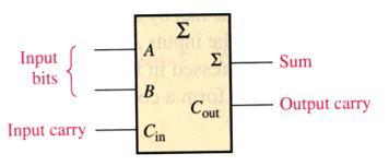
7 The Full-Adder The full-adder accepts two input bits and an input carry and generates a sum output and an output carry.
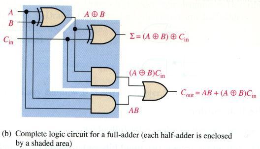

8 Full-Adder Logic
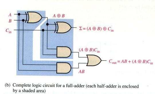
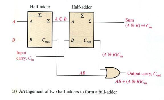
9 The Full-Adder

10 Parallel Binary Adders Two or more full adders are connected to form parallel binary adders. To add two binary numbers, a full-adder is required for each bit in the numbers. So, for 2-bit numbers, two adders are needed.

11 Parallel Binary Adders The carry output of each adder is connected to the carry input of the next higher-order adder.

12 Four-Bit Parallel Adders A group of 4 bits is called a nibble. A basic 4-bit parallel adder is implemented with four full-adder stages as shown.

13 Four-Bit Parallel Adders The carry output of each adder is connected to the carry input of the next higher-order adder as indicated. These are called internal carries.

14 Ripple Carry Adders Ripple carry adder
15 Look-Ahead Carry Adders

16 Look-Ahead Carry Adders Carry generation occurs when an output carry is produced (generated) internally by the full-adder. A carry is generated only when both input bits are 1s. The generated carry, C g, is expressed as the AND function of the two input bits, A and B. C g =AB


17 Look-Ahead Carry Adders Carry propagation occurs when the input carry is rippled to become the output carry. An input carry may be propagated by the fulladder when either or both of the input bits are 1s. The propagated carry, C p, is expressed as the OR function of the two input bits. C p =A+B
18 Confuse? Check this out
, and the propagated carry (C p ).")
19 Look-Ahead Carry Adders The output carry (C out ) of a full-adder can be expressed in terms of both: the generated carry (C g ), and the propagated carry (C p ). The relationship of the carries is expressed as: C out = C g + C p C in

20 Look-Ahead Carry Adders
21 Look-Ahead Carry Adders
22 Look-Ahead Carry Adders
23 Comparators
24 Comparators To compare the magnitude of two binary quantities to determine the relationship of those quantities. The simplest form a comparator determines whether two numbers are equal.
25 Equality XOR gate can be used as a 2-bit comparator. To compare binary numbers containing two bits each:
26 Inequality Many IC comparators provide additional outputs that indicate which of the two binary numbers being compared is the larger.

27 Inequality To determine an inequality of binary numbers A and B, you first examine the highest-order bit in each number: If A 3 =1 and B 3 =0 number A is greater than number B If A 3 =0 and B 3 =1 number A is less than number B If A 3 =B 3 you must examine the next lower bit position for an equality
28 Decoders
29 Decoders A decoder detects the presence of a specified combination of bits (code) on its inputs and indicates the presence of that code by a specified output level. In its general form, a decoder has n input lines to handle n bits and forms one to 2 n output lines to indicate the presence of one or more n-bit combinations.
30 The Basic Binary Decoder Suppose we need to determine when a binary 1001 occurs on the inputs of a digital.
31 The 4-Bit Decoder In order to decode all possible combinations of four bits, 16 decoding gates are required (2 4 =16). This type of decoder is commonly called either: A 4-line-to-16-line decoder, or A 1-of-16 decoder Decoding functions and truth table for a 4-line-to- 16-line decoder with active-low outputs see the next slide.

32 The 4-Bit Decoder


33 The 4-Bit Decoder 74HC154: 1-of-16 decoder

34 The BCD-to-Decimal Decoder The BCD-todecimal converts each BCD code into one of ten possible decimal digit indications. Called 4-lineto-10-line decoder or 1-of- 10 decoder
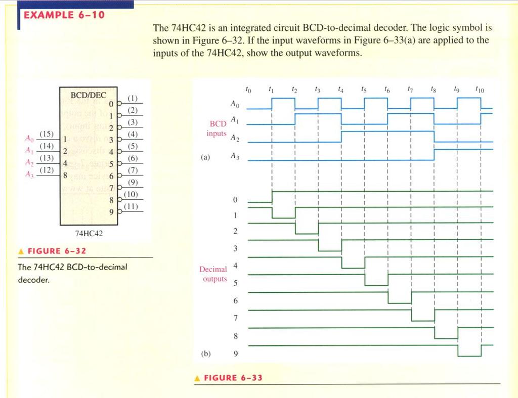
35 The BCD-to-Decimal Decoder

36 The BCD-to-7-Segment Decoder The BCD-to-7-segment decoder accepts the BCD code on its inputs and provides outputs to drive 7-segment display devices to produce a decimal readout.

37 The BCD-to-7-Segment Decoder (The Application)
38 Encoders
39 Encoders An encoder is a combinational logic ckt that essentially performs a reverse decoder function. An encoder accepts an active level on one of its inputs representing a digit, such as a decimal or octal digit, and converts it to a coded output such as BCD or binary. Encoders can also be devised to encode various symbols and alphabetic characters.

40 The Decimal-to-BCD Encoder It has 10 inputs and 4 outputs corresponding to the BCD code. A 3 = 8+9 A 2 = A 1 = A 0 =


41 The Decimal-to-BCD Encoder NOTE: A 0-digit input is not needed because the BCD outputs are all LOW when there are no HIGH input.
42 The Decimal-to-BCD Encoder (The Application)
43 Code Converters


44 Code Converters Binary-to-gray & gray-to-binary conversion
45 Multiplexers
46 Multiplexers (Data Selectors) A MUX is a device that allows digital information from several sources to be routed onto a single line for data transmission over that line to a common destination. The basic MUX has several data-input lines and a single output line. It also has data-select inputs, which permit digital data on any one of the inputs to be switched to the output line.


47 Multiplexers (Data Selectors)


48 Multiplexers (Data Selectors)

49 Multiplexers (Data Selectors)
50 Demultiplexers
51 Demultiplexers A DEMUX basically reverses the MUX function. It takes digital information from one line and distributes it to a given number of output lines. It also known as data distributor.

52 Demultiplexers
Chapter 8 Functions of Combinational Logic
 ETEC 23 Programmable Logic Devices Chapter 8 Functions of Combinational Logic Shawnee State University Department of Industrial and Engineering Technologies Copyright 27 by Janna B. Gallaher Basic Adders
Half-Adders. Ch.5 Summary. Chapter 5. Thomas L. Floyd
 Digital Fundamentals: A Systems Approach Functions of Combinational Logic Chapter 5 Half-Adders Basic rules of binary addition are performed by a half adder, which accepts two binary inputs (A and B) and
Combinational Logic Design
 Lab #2 Combinational Logic Design Objective: To introduce the design of some fundamental combinational logic building blocks. Preparation: Read the following experiment and complete the circuits where
MODULE 3. Combinational & Sequential logic
 MODULE 3 Combinational & Sequential logic Combinational Logic Introduction Logic circuit may be classified into two categories. Combinational logic circuits 2. Sequential logic circuits A combinational
Bachelor Level/ First Year/ Second Semester/ Science Full Marks: 60 Computer Science and Information Technology (CSc. 151) Pass Marks: 24
 Pass Marks: 24") 2065 Computer Science and Information Technology (CSc. 151) Pass Marks: 24 Time: 3 hours. Candidates are required to give their answers in their own words as for as practicable. Attempt any TWO questions:
2065 Computer Science and Information Technology (CSc. 151) Pass Marks: 24 Time: 3 hours. Candidates are required to give their answers in their own words as for as practicable. Attempt any TWO questions:
Find the equivalent decimal value for the given value Other number system to decimal ( Sample)
") VELAMMAL COLLEGE OF ENGINEERING AND TECHNOLOGY, MADURAI 65 009 Department of Information Technology Model Exam-II-Question bank PART A (Answer for all Questions) (8 X = 6) K CO Marks Find the equivalent
VELAMMAL COLLEGE OF ENGINEERING AND TECHNOLOGY, MADURAI 65 009 Department of Information Technology Model Exam-II-Question bank PART A (Answer for all Questions) (8 X = 6) K CO Marks Find the equivalent
Advanced Devices. Registers Counters Multiplexers Decoders Adders. CSC258 Lecture Slides Steve Engels, 2006 Slide 1 of 20
 Advanced Devices Using a combination of gates and flip-flops, we can construct more sophisticated logical devices. These devices, while more complex, are still considered fundamental to basic logic design.
Chapter 9 MSI Logic Circuits
 Chapter 9 MSI Logic Circuits Chapter 9 Objectives Selected areas covered in this chapter: Analyzing/using decoders & encoders in circuits. Advantages and disadvantages of LEDs and LCDs. Observation/analysis
PHYSICS 5620 LAB 9 Basic Digital Circuits and Flip-Flops
 PHYSICS 5620 LAB 9 Basic Digital Circuits and Flip-Flops Objective Construct a two-bit binary decoder. Study multiplexers (MUX) and demultiplexers (DEMUX). Construct an RS flip-flop from discrete gates.
R13 SET - 1 '' ''' '' ' '''' Code No: RT21053
 SET - 1 1. a) What are the characteristics of 2 s complement numbers? b) State the purpose of reducing the switching functions to minimal form. c) Define half adder. d) What are the basic operations in
1. Convert the decimal number to binary, octal, and hexadecimal.
 1. Convert the decimal number 435.64 to binary, octal, and hexadecimal. 2. Part A. Convert the circuit below into NAND gates. Insert or remove inverters as necessary. Part B. What is the propagation delay
R13. II B. Tech I Semester Regular Examinations, Jan DIGITAL LOGIC DESIGN (Com. to CSE, IT) PART-A
 PART-A") SET - 1 Note: Question Paper consists of two parts (Part-A and Part-B) Answer ALL the question in Part-A Answer any THREE Questions from Part-B a) What are the characteristics of 2 s complement numbers?
SET - 1 Note: Question Paper consists of two parts (Part-A and Part-B) Answer ALL the question in Part-A Answer any THREE Questions from Part-B a) What are the characteristics of 2 s complement numbers?
TIME SCHEDULE. MODULE TOPICS PERIODS 1 Number system & Boolean algebra 17 Test I 1 2 Logic families &Combinational logic
 COURSE TITLE : DIGITAL INSTRUMENTS PRINCIPLE COURSE CODE : 3075 COURSE CATEGORY : B PERIODS/WEEK : 4 PERIODS/SEMESTER : 72 CREDITS : 4 TIME SCHEDULE MODULE TOPICS PERIODS 1 Number system & Boolean algebra
Contents Circuits... 1
 Contents Circuits... 1 Categories of Circuits... 1 Description of the operations of circuits... 2 Classification of Combinational Logic... 2 1. Adder... 3 2. Decoder:... 3 Memory Address Decoder... 5 Encoder...
MUHAMMAD NAEEM LATIF MCS 3 RD SEMESTER KHANEWAL
 1. A stage in a shift register consists of (a) a latch (b) a flip-flop (c) a byte of storage (d) from bits of storage 2. To serially shift a byte of data into a shift register, there must be (a) one click
Encoders and Decoders: Details and Design Issues
 Encoders and Decoders: Details and Design Issues Edward L. Bosworth, Ph.D. TSYS School of Computer Science Columbus State University Columbus, GA 31907 bosworth_edward@colstate.edu Slide 1 of 25 slides
CS302 Digital Logic Design Solved Objective Midterm Papers For Preparation of Midterm Exam
 CS302 Digital Logic Design Solved Objective Midterm Papers For Preparation of Midterm Exam MIDTERM EXAMINATION Spring 2012 Question No: 1 ( Marks: 1 ) - Please choose one A SOP expression is equal to 1
Laboratory Objectives and outcomes for Digital Design Lab
 Class: SE Department of Information Technology Subject Logic Design Sem : III Course Objectives and outcomes for LD Course Objectives: Students will try to : COB1 Understand concept of various components.
Solution to Digital Logic )What is the magnitude comparator? Design a logic circuit for 4 bit magnitude comparator and explain it,
What is the magnitude comparator? Design a logic circuit for 4 bit magnitude comparator and explain it,") Solution to Digital Logic -2067 Solution to digital logic 2067 1.)What is the magnitude comparator? Design a logic circuit for 4 bit magnitude comparator and explain it, A Magnitude comparator is a combinational
Solution to Digital Logic -2067 Solution to digital logic 2067 1.)What is the magnitude comparator? Design a logic circuit for 4 bit magnitude comparator and explain it, A Magnitude comparator is a combinational
BCN1043. By Dr. Mritha Ramalingam. Faculty of Computer Systems & Software Engineering
 BCN1043 By Dr. Mritha Ramalingam Faculty of Computer Systems & Software Engineering mritha@ump.edu.my http://ocw.ump.edu.my/ authors Dr. Mohd Nizam Mohmad Kahar (mnizam@ump.edu.my) Jamaludin Sallim (jamal@ump.edu.my)
Tribhuvan University Institute of Science and Technology Bachelor of Science in Computer Science and Information Technology
 Tribhuvan University Institute of Science and Technology Bachelor of Science in Computer Science and Information Technology Course Title: Digital Logic Full Marks: 60 + 0 + 0 Course No.: CSC Pass Marks:
UNIVERSITI TEKNOLOGI MALAYSIA
 SULIT Faculty of Computing UNIVERSITI TEKNOLOGI MALAYSIA FINAL EXAMINATION SEMESTER I, 2016 / 2017 SUBJECT CODE : SUBJECT NAME : SECTION : TIME : DATE/DAY : VENUES : INSTRUCTIONS : Answer all questions
Semester III. Subject Name: Digital Electronics. Subject Code: 09CT0301. Diploma Branches in which this subject is offered: Computer Engineering
 Semester III Subject Name: Digital Electronics Subject Code: 09CT0301 Diploma Branches in which this subject is offered: Objective: The subject aims to prepare the students, To understand the basic of
NORTHWESTERN UNIVERSITY TECHNOLOGICAL INSTITUTE
 NORTHWESTERN UNIVERSITY TECHNOLOGICL INSTITUTE ECE 270 Experiment #8 DIGITL CIRCUITS Prelab 1. Draw the truth table for the S-R Flip-Flop as shown in the textbook. Draw the truth table for Figure 7. 2.
EEE130 Digital Electronics I Lecture #1_2. Dr. Shahrel A. Suandi
 EEE130 Digital Electronics I Lecture #1_2 Dr. Shahrel A. Suandi 1-4 Overview of Basic Logic Functions Digital systems are generally built from combinations of NOT, AND and OR logic elements The combinations
DIGITAL ELECTRONICS & it0203 Semester 3
 DIGITAL ELECTRONICS & it0203 Semester 3 P.Rajasekar & C.M.T.Karthigeyan Asst.Professor SRM University, Kattankulathur School of Computing, Department of IT 8/22/20 Disclaimer The contents of the slides
Engineering College. Electrical Engineering Department. Digital Electronics Lab
 Engineering College Electrical Engineering Department Digital Electronics Lab Prepared by: Dr. Samer Mayaleh Eng. Nuha Odeh 2009/2010-1 - CONTENTS Experiment Name Page 1- Measurement of Basic Logic Gates
Course Plan. Course Articulation Matrix: Mapping of Course Outcomes (COs) with Program Outcomes (POs) PSO-1 PSO-2
 with Program Outcomes (POs) PSO-1 PSO-2") Course Plan Semester: 4 - Semester Year: 2019 Course Title: DIGITAL ELECTRONICS Course Code: EC106 Semester End Examination: 70 Continuous Internal Evaluation: 30 Lesson Plan Author: Ms. CH SRIDEVI Last
Course Plan Semester: 4 - Semester Year: 2019 Course Title: DIGITAL ELECTRONICS Course Code: EC106 Semester End Examination: 70 Continuous Internal Evaluation: 30 Lesson Plan Author: Ms. CH SRIDEVI Last
Experiment (6) 2- to 4 Decoder. Figure 8.1 Block Diagram of 2-to-4 Decoder 0 X X
 2- to 4 Decoder. Figure 8.1 Block Diagram of 2-to-4 Decoder 0 X X") 8. Objectives : Experiment (6) Decoders / Encoders To study the basic operation and design of both decoder and encoder circuits. To describe the concept of active low and active-high logic signals. To
8. Objectives : Experiment (6) Decoders / Encoders To study the basic operation and design of both decoder and encoder circuits. To describe the concept of active low and active-high logic signals. To
Dev Bhoomi Institute Of Technology PRACTICAL INSTRUCTION SHEET EXPERIMENT NO. ISSUE NO. : ISSUE DATE: REV. NO. : REV. DATE : PAGE:
 Dev Bhoomi Institute Of Technology LABORATORY MANUAL PRACTICAL INSTRUCTION SHEET EXPERIMENT NO. ISSUE NO. : ISSUE DATE: REV. NO. : REV. DATE : PAGE: LABORATORY Name & Code: Digital Electronics SEMESTER:
1 Hour Sample Test Papers: Sample Test Paper 1. Roll No.
 6.1.2 Sample Test Papers: Sample Test Paper 1 Roll No. Institute Name: Course Code: EJ/EN/ET/EX/EV/IC/IE/IS/MU/DE/ED/ET/IU Subject: Principles of Digital Techniques Marks: 25 1 Hour 1. All questions are
DIGITAL SYSTEM DESIGN UNIT I (2 MARKS)
") DIGITAL SYSTEM DESIGN UNIT I (2 MARKS) 1. Convert Binary number (111101100) 2 to Octal equivalent. 2. Convert Binary (1101100010011011) 2 to Hexadecimal equivalent. 3. Simplify the following Boolean function
DIGITAL SYSTEM DESIGN UNIT I (2 MARKS) 1. Convert Binary number (111101100) 2 to Octal equivalent. 2. Convert Binary (1101100010011011) 2 to Hexadecimal equivalent. 3. Simplify the following Boolean function
Subject : EE6301 DIGITAL LOGIC CIRCUITS
 QUESTION BANK Programme : BE Subject : Semester / Branch : III/EEE UNIT 1 NUMBER SYSTEMS AND DIGITAL LOGIC FAMILIES Review of number systems, binary codes, error detection and correction codes (Parity
CS6201 UNIT I PART-A. Develop or build the following Boolean function with NAND gate F(x,y,z)=(1,2,3,5,7).
=(1,2,3,5,7).") VALLIAMMAI ENGINEERING COLLEGE SRM Nagar, Kattankulathur-603203 DEPARTMENT OF COMPUTER SCIENCE AND ENGINEERING Academic Year: 2015-16 BANK - EVEN SEMESTER UNIT I PART-A 1 Find the octal equivalent of hexadecimal
VALLIAMMAI ENGINEERING COLLEGE SRM Nagar, Kattankulathur-603203 DEPARTMENT OF COMPUTER SCIENCE AND ENGINEERING Academic Year: 2015-16 BANK - EVEN SEMESTER UNIT I PART-A 1 Find the octal equivalent of hexadecimal
MODU LE DAY. Class-A, B, AB and C amplifiers - basic concepts, power, efficiency Basic concepts of Feedback and Oscillation. Day 1
 DAY MODU LE TOPIC QUESTIONS Day 1 Day 2 Day 3 Day 4 I Class-A, B, AB and C amplifiers - basic concepts, power, efficiency Basic concepts of Feedback and Oscillation Phase Shift Wein Bridge oscillators.
Analogue Versus Digital [5 M]
![Analogue Versus Digital [5 M]](/thumbs/93/111640168.jpg "Analogue Versus Digital [5 M]") Q.1 a. Analogue Versus Digital [5 M] There are two basic ways of representing the numerical values of the various physical quantities with which we constantly deal in our day-to-day lives. One of the ways,
Q.1 a. Analogue Versus Digital [5 M] There are two basic ways of representing the numerical values of the various physical quantities with which we constantly deal in our day-to-day lives. One of the ways,
TYPICAL QUESTIONS & ANSWERS
 DIGITALS ELECTRONICS TYPICAL QUESTIONS & ANSWERS OBJECTIVE TYPE QUESTIONS Each Question carries 2 marks. Choose correct or the best alternative in the following: Q.1 The NAND gate output will be low if
Dev Bhoomi Institute Of Technology Department of Electronics and Communication Engineering PRACTICAL INSTRUCTION SHEET
 Dev Bhoomi Institute Of Technology Department of Electronics and Communication Engineering PRACTICAL INSTRUCTION SHEET LABORATORY MANUAL EXPERIMENT NO. 1 ISSUE NO. : ISSUE DATE: REV. NO. : REV. DATE :
PURBANCHAL UNIVERSITY
 [c] Implement a full adder circuit with a decoder and two OR gates. [4] III SEMESTER FINAL EXAMINATION-2006 Q. [4] [a] What is flip flop? Explain flip flop operating characteristics. [6] [b] Design and
Introduction to Digital Logic Missouri S&T University CPE 2210 Exam 3 Logistics
 Introduction to Digital Logic Missouri S&T University CPE 2210 Exam 3 Logistics Egemen K. Çetinkaya Egemen K. Çetinkaya Department of Electrical & Computer Engineering Missouri University of Science and
Midterm Exam 15 points total. March 28, 2011
 Midterm Exam 15 points total March 28, 2011 Part I Analytical Problems 1. (1.5 points) A. Convert to decimal, compare, and arrange in ascending order the following numbers encoded using various binary
QUICK GUIDE COMPUTER LOGICAL ORGANIZATION - OVERVIEW
 QUICK GUIDE http://www.tutorialspoint.com/computer_logical_organization/computer_logical_organization_quick_guide.htm COMPUTER LOGICAL ORGANIZATION - OVERVIEW Copyright tutorialspoint.com In the modern
VU Mobile Powered by S NO Group
 Question No: 1 ( Marks: 1 ) - Please choose one A 8-bit serial in / parallel out shift register contains the value 8, clock signal(s) will be required to shift the value completely out of the register.
DIGITAL FUNDAMENTALS
 DIGITAL FUNDAMENTALS A SYSTEMS APPROACH THOMAS L. FLOYD PEARSON Boston Columbus Indianapolis New York San Francisco Upper Saddle River Amsterdam Cape Town Dubai London Madrid Milan Munich Paris Montreal
Department of Computer Science and Engineering Question Bank- Even Semester:
 Department of Computer Science and Engineering Question Bank- Even Semester: 2014-2015 CS6201& DIGITAL PRINCIPLES AND SYSTEM DESIGN (Common to IT & CSE, Regulation 2013) UNIT-I 1. Convert the following
Registers and Counters
 Registers and Counters Clocked sequential circuit = F/Fs and combinational gates Register Group of flip-flops (share a common clock and capable of storing one bit of information) Consist of a group of
[2 credit course- 3 hours per week]
![[2 credit course- 3 hours per week]](/thumbs/94/121292011.jpg "[2 credit course- 3 hours per week]") Syllabus of Applied Electronics for F Y B Sc Semester- 1 (With effect from June 2012) PAPER I: Components and Devices [2 credit course- 3 hours per week] Unit- I : CIRCUIT THEORY [10 Hrs] Introduction;
Syllabus of Applied Electronics for F Y B Sc Semester- 1 (With effect from June 2012) PAPER I: Components and Devices [2 credit course- 3 hours per week] Unit- I : CIRCUIT THEORY [10 Hrs] Introduction;
Logic Design Viva Question Bank Compiled By Channveer Patil
 Logic Design Viva Question Bank Compiled By Channveer Patil Title of the Practical: Verify the truth table of logic gates AND, OR, NOT, NAND and NOR gates/ Design Basic Gates Using NAND/NOR gates. Q.1
WINTER 15 EXAMINATION Model Answer
 Important Instructions to examiners: 1) The answers should be examined by key words and not as word-to-word as given in the model answer scheme. 2) The model answer and the answer written by candidate
UNIT 1: DIGITAL LOGICAL CIRCUITS What is Digital Computer? OR Explain the block diagram of digital computers.
 UNIT 1: DIGITAL LOGICAL CIRCUITS What is Digital Computer? OR Explain the block diagram of digital computers. Digital computer is a digital system that performs various computational tasks. The word DIGITAL
TRAINING KITS ON DIGITAL ELECTRONIC EXPERIMENTS. Verify Truth table for TTL IC s AND, NOT, & NAND GATES
 TRAINING KITS ON DIGITAL ELECTRONIC EXPERIMENTS CEE 2800 Basic Logic Gates using TTL IC's (7 in 1) To verify the truth table For TTL AND, OR. NOT, NAND,NOR, EX-OR, & EX-NOR Gates. Instrument comprises
Chapter 3. Boolean Algebra and Digital Logic
 Chapter 3 Boolean Algebra and Digital Logic Chapter 3 Objectives Understand the relationship between Boolean logic and digital computer circuits. Learn how to design simple logic circuits. Understand how
 UNIT 1 NUMBER SYSTEMS AND DIGITAL LOGIC FAMILIES 1. Briefly explain the stream lined method of converting binary to decimal number with example. 2. Give the Gray code for the binary number (111) 2. 3.
Theory Lecture Day Topic Practical Day. Week. number systems and their inter-conversion Decimal, Binary. 3rd. 1st. 1st
 Lesson Plan Name of the Faculty : Priyanka Nain Discipline: Electronics & Communication Engg. Semester:5th Subject:DEMP Lesson Plan Duration: 15 Weeks Work Load(Lecture/Practical) per week (In Hours):
Page No.1. CS302 Digital Logic & Design_ Muhammad Ishfaq
 Page No.1 File Version Update: (Dated: 17-May-2011) This version of file contains: Content of the Course (Done) FAQ updated version.(these must be read once because some very basic definition and question
RAO PAHALD SINGH GROUP OF INSTITUTIONS BALANA(MOHINDER GARH)123029
123029") DIGITAL ELECTRONICS LAB( EE-224-F) DIGITAL ELECTRONICS LAB (EE-224-F) LAB MANUAL IV SEMESTER RAO PAHALD SINGH GROUP OF INSTITUTIONS BALANA(MOHINDER GARH)2329 Department Of Electronics & Communication Engg.
DIGITAL ELECTRONICS LAB( EE-224-F) DIGITAL ELECTRONICS LAB (EE-224-F) LAB MANUAL IV SEMESTER RAO PAHALD SINGH GROUP OF INSTITUTIONS BALANA(MOHINDER GARH)2329 Department Of Electronics & Communication Engg.
Operating Manual Ver.1.1
 Keyboard Encoder Operating Manual Ver.1.1 An ISO 9001 : 2000 company 94-101, Electronic Complex Pardesipura, Indore- 452010, India Tel : 91-731- 2570301/02, 4211100 Fax: 91-731- 2555643 e mail : info@scientech.bz
EXPERIMENT: 1. Graphic Symbol: OR: The output of OR gate is true when one of the inputs A and B or both the inputs are true.
 EXPERIMENT: 1 DATE: VERIFICATION OF BASIC LOGIC GATES AIM: To verify the truth tables of Basic Logic Gates NOT, OR, AND, NAND, NOR, Ex-OR and Ex-NOR. APPARATUS: mention the required IC numbers, Connecting
North Shore Community College
 North Shore Community College Course Number: IEL217 Section: MAL Course Name: Digital Electronics 1 Semester: Credit: 4 Hours: Three hours of Lecture, Two hours Laboratory per week Thursdays 8:00am (See
gate symbols will appear in schematic Dierent of a circuit. Standard gate symbols have been diagram Figures 5-3 and 5-4 show standard shapes introduce
 chapter is concerned with examples of basic This circuits including decoders, combinational xor gate and parity circuits, multiplexers, comparators, adders. Those basic building circuits frequently and
DIGITAL ELECTRONICS MCQs
 DIGITAL ELECTRONICS MCQs 1. A 8-bit serial in / parallel out shift register contains the value 8, clock signal(s) will be required to shift the value completely out of the register. A. 1 B. 2 C. 4 D. 8
AIM: To study and verify the truth table of logic gates
 EXPERIMENT: 1- LOGIC GATES AIM: To study and verify the truth table of logic gates LEARNING OBJECTIVE: Identify various Logic gates and their output. COMPONENTS REQUIRED: KL-31001 Digital Logic Lab( Main
Minnesota State College Southeast
 ELEC 2211: Digital Electronics II A. COURSE DESCRIPTION Credits: 4 Lecture Hours/Week: 2 Lab Hours/Week: 4 OJT Hours/Week: *.* Prerequisites: None Corequisites: None MnTC Goals: None Minnesota State College
 SUBJECT NAME : DIGITAL ELECTRONICS SUBJECT CODE : EC8392 1. State Demorgan s Theorem. QUESTION BANK PART A UNIT - I DIGITAL FUNDAMENTALS De Morgan suggested two theorems that form important part of Boolean
Chapter Contents. Appendix A: Digital Logic. Some Definitions
 A- Appendix A - Digital Logic A-2 Appendix A - Digital Logic Chapter Contents Principles of Computer Architecture Miles Murdocca and Vincent Heuring Appendix A: Digital Logic A. Introduction A.2 Combinational
4.S-[F] SU-02 June All Syllabus Science Faculty B.Sc. II Yr. Instrumentation Practice [Sem.III & IV] S.Lot
![4.S-[F] SU-02 June All Syllabus Science Faculty B.Sc. II Yr. Instrumentation Practice [Sem.III & IV] S.Lot](/thumbs/90/103282534.jpg "4.S-[F] SU-02 June All Syllabus Science Faculty B.Sc. II Yr. Instrumentation Practice [Sem.III & IV] S.Lot") [Sem.III & IV] S.Lot. - 1 - [Sem.III & IV] S.Lot. - 2 - [Sem.III & IV] S.Lot. - 3 - Syllabus B.Sc. ( Instrumentation Practice ) Second Year ( Third and Forth Semester ) ( Effective from June 2014 ) [Sem.III
[Sem.III & IV] S.Lot. - 1 - [Sem.III & IV] S.Lot. - 2 - [Sem.III & IV] S.Lot. - 3 - Syllabus B.Sc. ( Instrumentation Practice ) Second Year ( Third and Forth Semester ) ( Effective from June 2014 ) [Sem.III
Integrated Circuits 7
 7 IC Test Clip Series For temporary connections to DIP package components Heavy-duty spring loaded hinge provides positive contact 20 AWG insulated gold contacts Color: white 22103 Part No. Product No.
DIGITAL CIRCUIT LOGIC UNIT 9: MULTIPLEXERS, DECODERS, AND PROGRAMMABLE LOGIC DEVICES
 DIGITAL CIRCUIT LOGIC UNIT 9: MULTIPLEXERS, DECODERS, AND PROGRAMMABLE LOGIC DEVICES 1 Learning Objectives 1. Explain the function of a multiplexer. Implement a multiplexer using gates. 2. Explain the
CSE221- Logic Design, Spring 2003
 EE207: Digital Systems I, Semester I 2003/2004 CHAPTER 3 -ii: Combinational Logic Design Design Procedure, Encoders/Decoders (Sections 3.4 3.6) Overview Design Procedure Code Converters Binary Decoders
Semester 6 DIGITAL ELECTRONICS- core subject -10 Credit-4
 Semester 6 DIGITAL ELECTRONICS- core subject -10 Credit-4 Unit I Number system, Binary, decimal, octal, hexadecimal-conversion from one another-binary addition, subtraction, multiplication, division-binary
CprE 281: Digital Logic
 CprE 28: Digital Logic Instructor: Alexander Stoytchev http://www.ece.iastate.edu/~alexs/classes/ T Flip-Flops & JK Flip-Flops CprE 28: Digital Logic Iowa State University, Ames, IA Copyright Alexander
1. True/False Questions (10 x 1p each = 10p) (a) I forgot to write down my name and student ID number.
 (a) I forgot to write down my name and student ID number.") CprE 281: Digital Logic Midterm 2: Friday Oct 30, 2015 Student Name: Student ID Number: Lab Section: Mon 9-12(N) Mon 12-3(P) Mon 5-8(R) Tue 11-2(U) (circle one) Tue 2-5(M) Wed 8-11(J) Wed 6-9(Y) Thur 11-2(Q)
CprE 281: Digital Logic Midterm 2: Friday Oct 30, 2015 Student Name: Student ID Number: Lab Section: Mon 9-12(N) Mon 12-3(P) Mon 5-8(R) Tue 11-2(U) (circle one) Tue 2-5(M) Wed 8-11(J) Wed 6-9(Y) Thur 11-2(Q)
DEPARTMENT OF COMPUTER SCIENCE & ENGINEERING
 DRONACHARYA GROUP OF INSTITUTIONS, GREATER NOIDA Affiliated to Mahamaya Technical University, Noida Approved by AICTE DEPARTMENT OF COMPUTER SCIENCE & ENGINEERING Lab Manual for Computer Organization Lab
Digital Electronic Circuits Design & Laboratory Guideline
 D.2. Encoders Often we use diverse peripheral devices such as switches, numeric keypads and more in order to interface the analog world with the digital one and, along with the usage of these devices,
Principles of Computer Architecture. Appendix A: Digital Logic
 A-1 Appendix A - Digital Logic Principles of Computer Architecture Miles Murdocca and Vincent Heuring Appendix A: Digital Logic A-2 Appendix A - Digital Logic Chapter Contents A.1 Introduction A.2 Combinational
For Teacher's Use Only Q Total No. Marks. Q No Q No Q No
 FINALTERM EXAMINATION Spring 2010 CS302- Digital Logic Design (Session - 4) Time: 90 min Marks: 58 For Teacher's Use Only Q 1 2 3 4 5 6 7 8 Total No. Marks Q No. 9 10 11 12 13 14 15 16 Marks Q No. 17 18
LECTURE NOTES. ON Digital Circuit And Systems
 Digital circuit&systems LECTURE NOTES ON Digital Circuit And Systems 2018 2019 III B. Tech I Semester (JNTUA-R15) Mrs.M.CHANDINI, Assistant Professor CHADALAWADA RAMANAMMA ENGINEERING COLLEGE (AUTONOMOUS)
Digital Logic Design: An Overview & Number Systems
 Digital Logic Design: An Overview & Number Systems Analogue versus Digital Most of the quantities in nature that can be measured are continuous. Examples include Intensity of light during the day: The
Date: Author: New: Revision: x SAULT COLLEGE OF APPLIED ARTS & TECHNOLOGY SAULT STE. MARIE, ONTARIO ELN TWO
 SAULT COLLEGE OF APPLIED ARTS & TECHNOLOGY SAULT STE. MARIE, ONTARIO COURSE OUTLINE Course Title: DIGITAL ELECTRONICS Code No.: ELN 107-5 Program: ELECTRICAL/ELECTRONIC TECHNICIAN Semester: TWO Date: AUGUST
ECE 263 Digital Systems, Fall 2015
 ECE 263 Digital Systems, Fall 2015 REVIEW: FINALS MEMORY ROM, PROM, EPROM, EEPROM, FLASH RAM, DRAM, SRAM Design of a memory cell 1. Draw circuits and write 2 differences and 2 similarities between DRAM
CS302 - Digital Logic & Design
 AN OVERVIEW & NUMBER SYSTEMS Lesson No. 01 Analogue versus Digital Most of the quantities in nature that can be measured are continuous. Examples include Intensity of light during the da y: The intensity
Computer Architecture and Organization
 A-1 Appendix A - Digital Logic Computer Architecture and Organization Miles Murdocca and Vincent Heuring Appendix A Digital Logic A-2 Appendix A - Digital Logic Chapter Contents A.1 Introduction A.2 Combinational
SIGNETICS INTEGRATED CIRCUITS Low Power Schottky TTL 54LS00-74LS00 Series. Supply Current/typmA Delay/typns Quad 2-Input NAND Gate 54LS00/C,D
 SIGNETICS INTEGRATED CIRCUITS Low Power Schottky TTL 54LS00-74LS00 Series Rating Value Unit Voltage - V CC +7.0 V Input Voltage Range - V I -0.5 to +7.0 V Output Voltage - V out +5.5 V Operating Temperature
Lab #10 Hexadecimal-to-Seven-Segment Decoder, 4-bit Adder-Subtractor and Shift Register. Fall 2017
 University of Texas at El Paso Electrical and Computer Engineering Department EE 2169 Laboratory for Digital Systems Design I Lab #10 Hexadecimal-to-Seven-Segment Decoder, 4-bit Adder-Subtractor and Shift
BHARATHIDASAN ENGINEERING COLLEGE, NATTRAMPALLI DEPARTMENT OF ECE
 BHARATHIDASAN ENGINEERING COLLEGE, NATTRAMPALLI DEPARTMENT OF ECE CS6201 DIGITAL PRINCIPLES AND SYSTEM DESIGN 1 st year 2 nd semester CSE & IT Unit wise Important Part A and Part B Prepared by L.GOPINATH
Helping Material of CS302
 ABEL : Advanced Boolean Expression Language; a software compiler language for SPLD programming; a type of hardware description language (HDL) Adder : A digital circuit which forms the sum and carry of
Department of Electrical and Computer Engineering Mid-Term Examination Winter 2012
 1 McGill University Faculty of Engineering ECSE-221B Introduction to Computer Engineering Department of Electrical and Computer Engineering Mid-Term Examination Winter 2012 Examiner: Rola Harmouche Date:
List of the CMOS 4000 series Dual tri-input NOR Gate and Inverter Quad 2-input NOR gate Dual 4-input NOR gate
 List of the CMOS 4000 series 4000 - Dual tri-input NOR Gate and Inverter 4001 - Quad 2-input NOR gate 4002 - Dual 4-input NOR gate 4006-18 stage Shift register 4007 - Dual Complementary Pair Plus Inverter
Digital Fundamentals: A Systems Approach
 Digital Fundamentals: A Systems Approach Counters Chapter 8 A System: Digital Clock Digital Clock: Counter Logic Diagram Digital Clock: Hours Counter & Decoders Finite State Machines Moore machine: One
Digital Circuits ECS 371
 Digital Circuits ECS 37 Dr. Prapun Suksompong prapun@siit.tu.ac.th Lecture 0 Office Hours: BKD 360-7 Monday 9:00-0:30, :30-3:30 Tuesday 0:30-:30 Announcement HW4 posted on the course web site Chapter 5:
CS302 Glossary. address : The location of a given storage cell or group of cells in a memory; a unique memory location containing one byte.
 CS302 Glossary ABEL Advanced Boolean Expression Language; a software compiler language for SPLD programming; a type of hardware description language (HDL) Adder A digital circuit which forms the sum and
Nirma University Institute of Technology. Electronics and Communication Engineering Department. Course Policy
 Nirma University Institute of Technology Electronics and Communication Engineering Department Course Policy B. Tech Semester - III Academic Year: 2017 Course Code & Name : Credit Details : L T P C 4 2
EXPERIMENT 13 ITERATIVE CIRCUITS
 EE 2449 Experiment 13 Revised 4/17/2017 CALIFORNIA STATE UNIVERSITY LOS ANGELES Department of Electrical and Computer Engineering EE-246 Digital Logic Lab EXPERIMENT 13 ITERATIVE CIRCUITS Text: Mano, Digital
CSC Computer Architecture and Organization
 S 37 - omputer Architecture and Organization Lecture 6: Registers and ounters Registers A register is a group of flip-flops. Each flip-flop stores one bit of data; n flip-flops are required to store n
Electromania Problem statement discussion
 Electromania Problem statement discussion A Competition Basic Circuiting What is Electromania? Debuggin g Innovation Let s recall the previous lecture..!! Electronics Digital Analog Analog Digital Digital
Operating Manual Ver.1.1
 Johnson Counter Operating Manual Ver.1.1 An ISO 9001 : 2000 company 94-101, Electronic Complex Pardesipura, Indore- 452010, India Tel : 91-731- 2570301/02, 4211100 Fax: 91-731- 2555643 e mail : info@scientech.bz
LED BASED SNAKE GAME
 LED BASED SNAKE GAME Group 14 1 NAME ROLL NO MAJOR Muhammad Shoaib Hassan 14100005 Electrical Engineering Syed Muhammad Ali 14100167 Electrical Engineering Muhammad Ali Gulzar 14100017 Computer Science
Digital Networks and Systems Laboratory 2 Basic Digital Building Blocks Time 4 hours
 Digital Networks and Systems Laboratory 2 Basic Digital Building Blocks Time 4 hours Aim To investigate the basic digital circuit building blocks constructed from combinatorial logic or dedicated Integrated
Lecture 12. Amirali Baniasadi
 CENG 24 Digital Design Lecture 2 Amirali Baniasadi amirali@ece.uvic.ca This Lecture Chapter 6: Registers and Counters 2 Registers Sequential circuits are classified based in their function, e.g., registers.
Chapter 6 Registers and Counters
 EEA051 - Digital Logic 數位邏輯 Chapter 6 Registers and Counters 吳俊興國立高雄大學資訊工程學系 January 2006 Chapter 6 Registers and Counters 6-1 Registers 6-2 Shift Registers 6-3 Ripple Counters 6-4 Synchronous Counters